EP0079152A1 - Improved lubrication of conveyor chains - Google Patents
Improved lubrication of conveyor chains Download PDFInfo
- Publication number
- EP0079152A1 EP0079152A1 EP82305610A EP82305610A EP0079152A1 EP 0079152 A1 EP0079152 A1 EP 0079152A1 EP 82305610 A EP82305610 A EP 82305610A EP 82305610 A EP82305610 A EP 82305610A EP 0079152 A1 EP0079152 A1 EP 0079152A1
- Authority
- EP
- European Patent Office
- Prior art keywords
- lubricant
- water
- conveyor
- lubrication
- chain
- Prior art date
- Legal status (The legal status is an assumption and is not a legal conclusion. Google has not performed a legal analysis and makes no representation as to the accuracy of the status listed.)
- Withdrawn
Links
Images
Classifications
-
- F—MECHANICAL ENGINEERING; LIGHTING; HEATING; WEAPONS; BLASTING
- F16—ENGINEERING ELEMENTS AND UNITS; GENERAL MEASURES FOR PRODUCING AND MAINTAINING EFFECTIVE FUNCTIONING OF MACHINES OR INSTALLATIONS; THERMAL INSULATION IN GENERAL
- F16N—LUBRICATING
- F16N15/00—Lubrication with substances other than oil or grease; Lubrication characterised by the use of particular lubricants in particular apparatus or conditions
-
- B—PERFORMING OPERATIONS; TRANSPORTING
- B65—CONVEYING; PACKING; STORING; HANDLING THIN OR FILAMENTARY MATERIAL
- B65G—TRANSPORT OR STORAGE DEVICES, e.g. CONVEYORS FOR LOADING OR TIPPING, SHOP CONVEYOR SYSTEMS OR PNEUMATIC TUBE CONVEYORS
- B65G45/00—Lubricating, cleaning, or clearing devices
- B65G45/10—Cleaning devices
- B65G45/22—Cleaning devices comprising fluid applying means
-
- F—MECHANICAL ENGINEERING; LIGHTING; HEATING; WEAPONS; BLASTING
- F16—ENGINEERING ELEMENTS AND UNITS; GENERAL MEASURES FOR PRODUCING AND MAINTAINING EFFECTIVE FUNCTIONING OF MACHINES OR INSTALLATIONS; THERMAL INSULATION IN GENERAL
- F16H—GEARING
- F16H57/00—General details of gearing
- F16H57/04—Features relating to lubrication or cooling or heating
- F16H57/05—Features relating to lubrication or cooling or heating of chains
Definitions
- This invention relates generally to a lubrication system for a conveyor chain or conveyor belt of the type used in bottling plants. More specifically, the invention involves the separate application of lubricant and water to a conveyor belt or chain.
- the separation of lubricant and water has several advantages. This permits application of lubricant to points along the belt that require lubrication at a given time. Furthermore foam is reduced. Also in cases where only hard water is available, plugging of the lubrication nozzle is prevented, because calcium and magnesium soaps are not formed in the lubrication container.
- a common system for conveying bottles in a bottling plant is a continuous moving conveyor belt or chain.
- These chains may be typically twenty feet long and generally include mechanisms for moving the bottles onto the chain plates at one end and for removing the bottles at the other end.
- both in the moving parts of the chain and also to facilitate movement of bottles onto and off from the surfaces of the chain it is necessary to keep the entire chain system continuously lubricated.
- over lubrication is to be avoided, since this may generate quantities of foam that are impossible to deal with.
- the instant invention facilitates addition of the correct amount of lubricant to a given chain by adding the lubricant and the water to the chain from separate nozzles.
- nozzles can be spaced along the conveyor belt for addition of lubricant and/or water at given points. At some points lubricant will be needed, but no water. At other points both lubricant and water will be needed. At still other points only water will be needed. And there will be some areas where neither additive will be required at a given time.
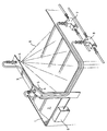
- the drawing shows an embodiment of the invention, indicating apparatus for adding lubricant and water to a portion of a chain system.
- the tray container for the conveyor chain or belt 2 At 1 is shown the tray container for the conveyor chain or belt 2.
- nozzle 5 At 3 is shown a support arm carrying nozzle 4, which is the water spray, and nozzle 5, which is the lubricant spray.
- the spray pattern 6, for the water spray indicates the area of the conveyor system covered by the water spray.
- the lubricant nozzle 5 simply drips the lubricant concentrate.
- Headers 7 and 8 respectively provide sources for the water and the lubricant.
- 9 is an electrical power and control box for the accurate control of the lubricant solenoid valve.
- the sprays reach both the plate surfaces and their supporting sprockets (not shown).
- lubricating beverage plant chains there are two methods of lubricating beverage plant chains. First, and most common, is to dilute a liquid concentrate with water by means of a dilution tank or by a proportioner pump which injects the concentrated lubricant into a water line. The diluted lubricant is then dispensed either by a drip dispenser or by a spray nozzle. Sequestrants or softened water must be used to prevent formation of insoluble hard water soaps which will plug lines, nozzles and spray heads.
- the second method is to place a solid bar of soap onto the leading end of the conveyor. Water is dripped onto the bars to dissolve the soap and lubricate the conveyor.
- This invention applies the concentrated liquid lubricant in drops or sprays directly onto the conveyor. Dilution water is sprayed onto the conveyor after the lubricant. Amount of lubricant usage can be reduced by controlling application at each lubrication point to the required concentration for proper lubrication and foam level at that point. By not premixing the lubricant and water, sequestrants or other forms of water treatment for the control of hard water cations are not necessary. Through the separate water line cleaners and sanitizers can be applied to the conveyor as necessary.
- Evaluations were performed on a 7-inch by 12 foot stainless steel conveyor chain supported by cast iron carriers.
- a digital electronic measurement device was mounted at the end of the conveyor to measure the amount of force, registered in pounds, exerted by 29 glass bottles filled with water for a combined weight of 41 pounds.
- To simulate heavier conveyor loading a second group of 33 bottles provided an additional load of 46.6 pounds to the conveyor. This second group was separated from the initial group of bottles and did not apply force directly to the electronic equipment.
- a strip chart recorder was used to record the information from the electronic equipment.
- the digital equipment measures the force exerted by the moving conveyor on the bottles, which in this test were held stationary the better to test the lubrication. As lubrication is improved the force between the conveyor and the bottles is reduced. Hence, the lower the value from the digital equipment the better the lubricity. D ue to the sensitivity of the equipment the smooth movement of the conveyor chain can be evaluated. A range of force values are produced which is called the span. The width of the span is directly proportional to the smoothness of motion of the conveyor chain.
- Three liquid concentrated lubricants which represents typical types of conveyor lubricants commonly found in the market, were chosen to evaluate the separate dispensing of concentrated lubricant and dilution water. To establish a method of comparison between the two types of dispensing methods the three liquid concentrates were first evaluated using conventional spray nozzle dispenser applying a prediluted solution (control).
- twin spray nozzles were used to apply a 1:100 dilution of concentrated lubricant and deionized water at a flow rate of 97 ml/min. Results of this test are listed on Table 1. Deionized water had to be used in this evaluation to prevent the formation of insoluble calcium soaps which would plug the spray nozzles:
- each concentrate was then evaluated using the drip dispenser (this invention).
- the liquid concentrated lubricant was dripped directly onto the conveyor at a single point.
- the twin spray nozzles were used to apply the dilution water.
- Tap water was used in this evalution with an average hardness of 8 grains to demonstrate that water treatment is not necessary for the operation of the system.
- a percentage timer was used to vary the flow rate.
- a second timer and solenoid controlled the flow rate of the dilution water.
- a control run was first made, using an aqueous solution of a given lubricant by spraying same at 97 ml/minute through the nozzle dispenser.
- a comparative run was made using the same test set-up except that lubricant and water were applied through separate nozzles (this invention) and at several different flow rates. The lubricant was "dripped" and the following water application was sprayed.
- Lubricant A is a liquid concentrated lubricant composed of 28% potassium and 4% amine soaps of vegetable fatty acids, 7.6% trisodium salt of ethylene diamine tetracetic acid, 2% nonionic surfactant, 3% glycol with the balance water.
- the fatty acids consisted of 4.7% caprylic, 3.3% capric, 1.4% palmitic, 1.40% stearic, 46.5% oleic, and 42.7% linoleic.
- the nonionic surfactant used was nonylphenoxypoly(ethyleneoxy) ethanol. When dispensed through the spray nozzle dispenser an average force reading of 5.0 pounds with a span of 1.5 pounds was recorded. A large excess of foam was produced which climbed the bottles and covered the floor. See Table 1.
- the drip dispenser (which initially produced large excesses of foam) allowed the lubricant flow rate to be reduced 0.40 ml/min. The lowest force readings were obtained at a lubricant flow rate of 0.40 ml/min, water flow rate of 44.6 ml/min for a force of 3.4 pounds and a span of 1.25 pounds. Foam level was also reduced to a very low level where it did not climb the bottles or fall on the floor.
- Lubricant B is a liquid lubricant concentrate composed of 19.0% potassium soaps of mixed vegetable fatty acids, 1.8% trisodium salt of ethylene diamine tetracetic acid, 4.0% of the aforesaid nonionic surfactant with the balance water.
- the fatty acids consisted of 3.6% caprylic, 19.2% lauric, 8.0% myristic, 4.9% palmitic, 1.7% stearic, 34.3% oleic, and 28.3% linoleic.
- Using the spray nozzle dispenser an average force value of 4.63 pounds with a span of 1.25 pounds was produced.
- excessive foam was a problem.
- a heavy thick foam was produced which climbed the bottles and accumulated on the floor. See Table 1.
- the drip dispenser reduced the force value to 3.63 pounds with a span of 1.25 pounds. This was obtained at a lubricant flow rate of 0.63 ml/min and a water flow of 37.6 ml/min.
- the foam was a very low wet film that did not climb the bottles or fall on the floor yet provided the detergency necessary to keep the conveyor clean.
- the drip dispenser improved lubricity by 21.6%, the span remained the same and lubricant usage was cut by 35%. Further information is given on Table 3.
- Lubricant C a liquid concentrate composed of 29.5% potassium soaps of mixed vegetable fatty acids, 0.15% sodium gluconate with the balance water.
- the fatty acids consisted of 1.4% caprylic, 3.4% lauric, 1.50% myristic, 4.5% palmitic, 1.7% stearic, 43.2% oleic, and 44.7% linoleic.
- the spray nozzle system produced force values of 4.4 pounds with a span of 1.25 pounds. As with the other lubricants when dispensed with the spray nozzles excessive amounts of foam are produced which climb the bottles and interfere with the bottling operation. See Table 1.
- the results of the three test lubricants indicate that the drip dispenser system can (1) improve lubricity by the direct application of concentrated lubricant to the conveyor, (2) reduce lubricant usage per point, (3) be controlled to provide the desired amount of lubrication at each point, (4) control the amount of foaming which can interfere with bottling operations, (5) eliminate the need for water treatment to control hard water cations, (6) can be used with sequestered or non-sequestered system, and (7) can be used with alkali metal soap lubricants, triethanolamine soap lubricants and semi-synthetic lubricants.
- hard water water containing 60-180 mg/liter equivalent CaC0 3 .
Abstract
Conveyor chains, such as those used in a bottling plant, are lubricated by means of a lubricant concentrate applicator followed by a separate water applicator. The flow of lubricant and water is independently controlled, thereby eliminating wasteful over lubrication and precluding under lubrication at a given point on the conveyor chain. Also absence of hard water in the lubricant applicator prevents formation of calcium and magnesium soaps that tend to clog the nozzle.
Description
- This invention relates generally to a lubrication system for a conveyor chain or conveyor belt of the type used in bottling plants. More specifically, the invention involves the separate application of lubricant and water to a conveyor belt or chain. The separation of lubricant and water has several advantages. This permits application of lubricant to points along the belt that require lubrication at a given time. Furthermore foam is reduced. Also in cases where only hard water is available, plugging of the lubrication nozzle is prevented, because calcium and magnesium soaps are not formed in the lubrication container.
- As is well known, a common system for conveying bottles in a bottling plant is a continuous moving conveyor belt or chain. These chains may be typically twenty feet long and generally include mechanisms for moving the bottles onto the chain plates at one end and for removing the bottles at the other end. In order to reduce friction, both in the moving parts of the chain and also to facilitate movement of bottles onto and off from the surfaces of the chain it is necessary to keep the entire chain system continuously lubricated. On the other hand over lubrication is to be avoided, since this may generate quantities of foam that are impossible to deal with. The instant invention facilitates addition of the correct amount of lubricant to a given chain by adding the lubricant and the water to the chain from separate nozzles. In this way nozzles can be spaced along the conveyor belt for addition of lubricant and/or water at given points. At some points lubricant will be needed, but no water. At other points both lubricant and water will be needed. At still other points only water will be needed. And there will be some areas where neither additive will be required at a given time.
- The drawing shows an embodiment of the invention, indicating apparatus for adding lubricant and water to a portion of a chain system. In this perspective view, at 1 is shown the tray container for the conveyor chain or
belt 2. At 3 is shown a support arm carrying nozzle 4, which is the water spray, andnozzle 5, which is the lubricant spray. The spray pattern 6, for the water spray, indicates the area of the conveyor system covered by the water spray. Thelubricant nozzle 5 simply drips the lubricant concentrate. Headers 7 and 8 respectively provide sources for the water and the lubricant. 9 is an electrical power and control box for the accurate control of the lubricant solenoid valve. The sprays reach both the plate surfaces and their supporting sprockets (not shown). - Generally there are two methods of lubricating beverage plant chains. First, and most common, is to dilute a liquid concentrate with water by means of a dilution tank or by a proportioner pump which injects the concentrated lubricant into a water line. The diluted lubricant is then dispensed either by a drip dispenser or by a spray nozzle. Sequestrants or softened water must be used to prevent formation of insoluble hard water soaps which will plug lines, nozzles and spray heads. The second method is to place a solid bar of soap onto the leading end of the conveyor. Water is dripped onto the bars to dissolve the soap and lubricate the conveyor.
- However, on any conveyor chain the use of one fixed concentration as in prior practice inevitably leads to lubrication problems due to under use at some points alJng the conveyor line (inadequate lubrication) and over use at other points (waste of product).
- This invention applies the concentrated liquid lubricant in drops or sprays directly onto the conveyor. Dilution water is sprayed onto the conveyor after the lubricant. Amount of lubricant usage can be reduced by controlling application at each lubrication point to the required concentration for proper lubrication and foam level at that point. By not premixing the lubricant and water, sequestrants or other forms of water treatment for the control of hard water cations are not necessary. Through the separate water line cleaners and sanitizers can be applied to the conveyor as necessary.
- Evaluations were performed on a 7-inch by 12 foot stainless steel conveyor chain supported by cast iron carriers. A digital electronic measurement device was mounted at the end of the conveyor to measure the amount of force, registered in pounds, exerted by 29 glass bottles filled with water for a combined weight of 41 pounds. To simulate heavier conveyor loading a second group of 33 bottles provided an additional load of 46.6 pounds to the conveyor. This second group was separated from the initial group of bottles and did not apply force directly to the electronic equipment. A strip chart recorder was used to record the information from the electronic equipment.
- The digital equipment measures the force exerted by the moving conveyor on the bottles, which in this test were held stationary the better to test the lubrication. As lubrication is improved the force between the conveyor and the bottles is reduced. Hence, the lower the value from the digital equipment the better the lubricity. Due to the sensitivity of the equipment the smooth movement of the conveyor chain can be evaluated. A range of force values are produced which is called the span. The width of the span is directly proportional to the smoothness of motion of the conveyor chain.
- Three liquid concentrated lubricants, which represents typical types of conveyor lubricants commonly found in the market, were chosen to evaluate the separate dispensing of concentrated lubricant and dilution water. To establish a method of comparison between the two types of dispensing methods the three liquid concentrates were first evaluated using conventional spray nozzle dispenser applying a prediluted solution (control).
- For adequate coverage of the conveyor, twin spray nozzles were used to apply a 1:100 dilution of concentrated lubricant and deionized water at a flow rate of 97 ml/min. Results of this test are listed on Table 1. Deionized water had to be used in this evaluation to prevent the formation of insoluble calcium soaps which would plug the spray nozzles:
- Each concentrate was then evaluated using the drip dispenser (this invention). The liquid concentrated lubricant was dripped directly onto the conveyor at a single point. The twin spray nozzles were used to apply the dilution water. Tap water was used in this evalution with an average hardness of 8 grains to demonstrate that water treatment is not necessary for the operation of the system. After a drip rate for the lubricant concentrate was established a percentage timer was used to vary the flow rate. A second timer and solenoid controlled the flow rate of the dilution water.
- A description and results for each of the lubricants tested is given below.
- In the following examples, a control run was first made, using an aqueous solution of a given lubricant by spraying same at 97 ml/minute through the nozzle dispenser. Next, a comparative run was made using the same test set-up except that lubricant and water were applied through separate nozzles (this invention) and at several different flow rates. The lubricant was "dripped" and the following water application was sprayed.
- Lubricant A is a liquid concentrated lubricant composed of 28% potassium and 4% amine soaps of vegetable fatty acids, 7.6% trisodium salt of ethylene diamine tetracetic acid, 2% nonionic surfactant, 3% glycol with the balance water. The fatty acids consisted of 4.7% caprylic, 3.3% capric, 1.4% palmitic, 1.40% stearic, 46.5% oleic, and 42.7% linoleic. The nonionic surfactant used was nonylphenoxypoly(ethyleneoxy) ethanol. When dispensed through the spray nozzle dispenser an average force reading of 5.0 pounds with a span of 1.5 pounds was recorded. A large excess of foam was produced which climbed the bottles and covered the floor. See Table 1.
- The drip dispenser (which initially produced large excesses of foam) allowed the lubricant flow rate to be reduced 0.40 ml/min. The lowest force readings were obtained at a lubricant flow rate of 0.40 ml/min, water flow rate of 44.6 ml/min for a force of 3.4 pounds and a span of 1.25 pounds. Foam level was also reduced to a very low level where it did not climb the bottles or fall on the floor.
- This represents an improvement in lubricity by 32%, an improvement in the span by 16.7 and a reduction in lubricant usage by 58.8% over the spray nozzle dispenser. Table 2 contains the results of the various lubricant and water flow rates.
- Lubricant B is a liquid lubricant concentrate composed of 19.0% potassium soaps of mixed vegetable fatty acids, 1.8% trisodium salt of ethylene diamine tetracetic acid, 4.0% of the aforesaid nonionic surfactant with the balance water. The fatty acids consisted of 3.6% caprylic, 19.2% lauric, 8.0% myristic, 4.9% palmitic, 1.7% stearic, 34.3% oleic, and 28.3% linoleic. Using the spray nozzle dispenser an average force value of 4.63 pounds with a span of 1.25 pounds was produced. As with the previous lubricant excessive foam was a problem. A heavy thick foam was produced which climbed the bottles and accumulated on the floor. See Table 1.
- The drip dispenser reduced the force value to 3.63 pounds with a span of 1.25 pounds. This was obtained at a lubricant flow rate of 0.63 ml/min and a water flow of 37.6 ml/min. The foam was a very low wet film that did not climb the bottles or fall on the floor yet provided the detergency necessary to keep the conveyor clean. ,In this example the drip dispenser improved lubricity by 21.6%, the span remained the same and lubricant usage was cut by 35%. Further information is given on Table 3.
- Lubricant C, a liquid concentrate composed of 29.5% potassium soaps of mixed vegetable fatty acids, 0.15% sodium gluconate with the balance water. The fatty acids consisted of 1.4% caprylic, 3.4% lauric, 1.50% myristic, 4.5% palmitic, 1.7% stearic, 43.2% oleic, and 44.7% linoleic. The spray nozzle system produced force values of 4.4 pounds with a span of 1.25 pounds. As with the other lubricants when dispensed with the spray nozzles excessive amounts of foam are produced which climb the bottles and interfere with the bottling operation. See Table 1.
- With the drip dispenser the force value dropped to 2.4 pounds with a span of 1.25 pounds. Foaming was reduced to a thin wet dispersed foam. This was achieved at a lubricant flow of 0.78 ml/min and a water flow of 44.6 ml/min. The drip dispenser improved lubricity by 45.5% while reducing lubricant usage by 19.6%. Table 4 presents the results of the various lubricant and water flow rates.
- The results of the three test lubricants indicate that the drip dispenser system can (1) improve lubricity by the direct application of concentrated lubricant to the conveyor, (2) reduce lubricant usage per point, (3) be controlled to provide the desired amount of lubrication at each point, (4) control the amount of foaming which can interfere with bottling operations, (5) eliminate the need for water treatment to control hard water cations, (6) can be used with sequestered or non-sequestered system, and (7) can be used with alkali metal soap lubricants, triethanolamine soap lubricants and semi-synthetic lubricants.
- By hard water is meant water containing 60-180 mg/liter equivalent CaC03.


Claims (3)
1. Method of lubricating a moving conveyor chain comprising adding lubricant and water to the chain through separate sources.
2. Method according to Claim 1 in which the water is hard water.
3. Method according to Claim 1 in which the lubricant is applied first, then the water.
Applications Claiming Priority (2)
| Application Number | Priority Date | Filing Date | Title |
|---|---|---|---|
| US31861081A | 1981-11-05 | 1981-11-05 | |
| US318610 | 1981-11-05 |
Publications (1)
| Publication Number | Publication Date |
|---|---|
| EP0079152A1 true EP0079152A1 (en) | 1983-05-18 |
Family
ID=23238883
Family Applications (1)
| Application Number | Title | Priority Date | Filing Date |
|---|---|---|---|
| EP82305610A Withdrawn EP0079152A1 (en) | 1981-11-05 | 1982-10-21 | Improved lubrication of conveyor chains |
Country Status (4)
| Country | Link |
|---|---|
| EP (1) | EP0079152A1 (en) |
| JP (1) | JPS58125513A (en) |
| AU (1) | AU8983282A (en) |
| ZA (1) | ZA827640B (en) |
Cited By (8)
| Publication number | Priority date | Publication date | Assignee | Title |
|---|---|---|---|---|
| EP0169723A2 (en) * | 1984-07-24 | 1986-01-29 | Diversey Engineering (Europe) Limited | Method and apparatus for treating a plurality of zones of a processing line |
| FR2620903A1 (en) * | 1987-09-25 | 1989-03-31 | Henkel France | Method and installation for cleaning movable transporters in canneries |
| US5320132A (en) * | 1991-10-24 | 1994-06-14 | H.B. Fuller Company | Modular lubrication multiple concentration control apparatus |
| WO1995008497A1 (en) * | 1993-09-23 | 1995-03-30 | Lang Apparatebau Gmbh | Installation and process for lubricating, cleaning and/or disinfecting conveyor belts or chains |
| WO2001027005A1 (en) * | 1999-10-08 | 2001-04-19 | Ecolab Inc. | Apparatus and method for the controlled lubrication and cleaning of conveyors |
| WO2002020381A1 (en) * | 2000-09-09 | 2002-03-14 | Lang Apparatebau Gmbh | Method and installation for maintaining the easy running of chain conveyors |
| DE19845619B4 (en) * | 1998-10-05 | 2004-04-29 | Habla Chemie Gmbh | Nozzle rack for a conveyor belt |
| CN107882969A (en) * | 2017-12-28 | 2018-04-06 | 洛阳明创矿山冶金设备有限公司 | A kind of reducer protecting device |
Families Citing this family (4)
| Publication number | Priority date | Publication date | Assignee | Title |
|---|---|---|---|---|
| US7741257B2 (en) | 2005-03-15 | 2010-06-22 | Ecolab Inc. | Dry lubricant for conveying containers |
| US7745381B2 (en) | 2005-03-15 | 2010-06-29 | Ecolab Inc. | Lubricant for conveying containers |
| CN104987944A (en) | 2010-09-24 | 2015-10-21 | 艺康美国股份有限公司 | Conveyor lubricants including emulsions and methods employing them |
| WO2014164468A1 (en) | 2013-03-11 | 2014-10-09 | Ecolab Usa Inc. | Lubrication of transfer plates using an oil or oil in water emulsions |
Citations (3)
| Publication number | Priority date | Publication date | Assignee | Title |
|---|---|---|---|---|
| US3051264A (en) * | 1960-10-14 | 1962-08-28 | Robert L Batchelor | Lubrication system and method for chain conveyor |
| GB1297917A (en) * | 1968-12-19 | 1972-11-29 | ||
| US4262776A (en) * | 1978-09-13 | 1981-04-21 | H. B. Fuller Company | Conveyor lubricating system |
-
1982
- 1982-10-19 ZA ZA827640A patent/ZA827640B/en unknown
- 1982-10-21 EP EP82305610A patent/EP0079152A1/en not_active Withdrawn
- 1982-10-27 AU AU89832/82A patent/AU8983282A/en not_active Abandoned
- 1982-11-04 JP JP57193927A patent/JPS58125513A/en active Pending
Patent Citations (3)
| Publication number | Priority date | Publication date | Assignee | Title |
|---|---|---|---|---|
| US3051264A (en) * | 1960-10-14 | 1962-08-28 | Robert L Batchelor | Lubrication system and method for chain conveyor |
| GB1297917A (en) * | 1968-12-19 | 1972-11-29 | ||
| US4262776A (en) * | 1978-09-13 | 1981-04-21 | H. B. Fuller Company | Conveyor lubricating system |
Cited By (14)
| Publication number | Priority date | Publication date | Assignee | Title |
|---|---|---|---|---|
| EP0169723A2 (en) * | 1984-07-24 | 1986-01-29 | Diversey Engineering (Europe) Limited | Method and apparatus for treating a plurality of zones of a processing line |
| US4627457A (en) * | 1984-07-24 | 1986-12-09 | Diversey Corporation | Method and apparatus for treating a plurality of zones of a processing line |
| EP0169723A3 (en) * | 1984-07-24 | 1987-02-04 | Diversey Engineering (Europe) Limited | Method and apparatus for treating a plurality of zones of a processing line |
| FR2620903A1 (en) * | 1987-09-25 | 1989-03-31 | Henkel France | Method and installation for cleaning movable transporters in canneries |
| US5320132A (en) * | 1991-10-24 | 1994-06-14 | H.B. Fuller Company | Modular lubrication multiple concentration control apparatus |
| US5758761A (en) * | 1993-09-23 | 1998-06-02 | Lang Apparatebau Gmbh | Installation and a process for lubricating, cleaning and/or disinfecting conveyor belts or chains |
| WO1995008497A1 (en) * | 1993-09-23 | 1995-03-30 | Lang Apparatebau Gmbh | Installation and process for lubricating, cleaning and/or disinfecting conveyor belts or chains |
| DE19845619B4 (en) * | 1998-10-05 | 2004-04-29 | Habla Chemie Gmbh | Nozzle rack for a conveyor belt |
| WO2001027005A1 (en) * | 1999-10-08 | 2001-04-19 | Ecolab Inc. | Apparatus and method for the controlled lubrication and cleaning of conveyors |
| US6302263B1 (en) | 1999-10-08 | 2001-10-16 | Ecolab, Inc. | Apparatus and method for the controlled lubrication and cleaning of conveyors |
| US6575291B2 (en) | 1999-10-08 | 2003-06-10 | Ecolab Inc. | Apparatus and method for the controlled lubrication and cleaning of conveyors |
| WO2002020381A1 (en) * | 2000-09-09 | 2002-03-14 | Lang Apparatebau Gmbh | Method and installation for maintaining the easy running of chain conveyors |
| CN107882969A (en) * | 2017-12-28 | 2018-04-06 | 洛阳明创矿山冶金设备有限公司 | A kind of reducer protecting device |
| CN107882969B (en) * | 2017-12-28 | 2023-12-01 | 陕西乾远机械设备有限公司 | Speed reducer protection device |
Also Published As
| Publication number | Publication date |
|---|---|
| JPS58125513A (en) | 1983-07-26 |
| ZA827640B (en) | 1983-08-31 |
| AU8983282A (en) | 1983-05-12 |
Similar Documents
| Publication | Publication Date | Title |
|---|---|---|
| EP0079152A1 (en) | Improved lubrication of conveyor chains | |
| US4839067A (en) | Process for lubricating and cleaning of bottle conveyor belts in the beverage industry | |
| EP1842898B1 (en) | Use of lubricant composition for lubricating a conveyor belt | |
| US6372698B1 (en) | Lubricant for chain conveyor belts and its use | |
| JP2763345B2 (en) | A soap-free aqueous lubricating formulation | |
| US4627457A (en) | Method and apparatus for treating a plurality of zones of a processing line | |
| JP2002527574A (en) | Method for lubricating conveyor systems with lubricants containing phosphate esters of ethoxylated fatty acid amides | |
| CA2141811A1 (en) | A lubricant concentrate and an aqueous lubricant solution based on fatty amines, a process for its production and its use | |
| EP2105493B1 (en) | Dry lubrication method employing oil-based lubricants | |
| EP0044458B1 (en) | Lubricant composition | |
| US5747431A (en) | Lubricant compositions | |
| EP1646706B1 (en) | Chain lubricants | |
| US6780254B1 (en) | Method and facility for lubricating and cleaning filling facilities for beverages or foodstuffs | |
| US20210214636A1 (en) | Lubricant compositions and methods for using the same | |
| US7462584B2 (en) | Lubricant concentrate based on alcohols | |
| AU680095B2 (en) | Lubricant compositions | |
| JP3939784B2 (en) | Conveyor lubricant and method for producing the same | |
| JP3994536B2 (en) | Lubricant composition | |
| WO2023203542A1 (en) | Lubricant compositions and methods of dry lubricating surface using the same | |
| CN116574553A (en) | Wet lubricant for conveyor belt and preparation method and application thereof | |
| CA1173821A (en) | Lubricant composition | |
| JP2021055116A (en) | Lubricant composition for belt conveyor and method for improving lubricity of belt conveyor | |
| WO1999061567A1 (en) | Lubricant compositions | |
| MXPA96002746A (en) | Lubrican compositions |
Legal Events
| Date | Code | Title | Description |
|---|---|---|---|
| PUAI | Public reference made under article 153(3) epc to a published international application that has entered the european phase |
Free format text: ORIGINAL CODE: 0009012 |
|
| AK | Designated contracting states |
Designated state(s): DE FR GB IT NL |
|
| 17P | Request for examination filed |
Effective date: 19831104 |
|
| STAA | Information on the status of an ep patent application or granted ep patent |
Free format text: STATUS: THE APPLICATION HAS BEEN WITHDRAWN |
|
| 18W | Application withdrawn |
Withdrawal date: 19840206 |
|
| RIN1 | Information on inventor provided before grant (corrected) |
Inventor name: COFFREY, CHARLES R. Inventor name: COLEMAN, KENNETH C. |