EP0169723A2 - Method and apparatus for treating a plurality of zones of a processing line - Google Patents
Method and apparatus for treating a plurality of zones of a processing line Download PDFInfo
- Publication number
- EP0169723A2 EP0169723A2 EP85305186A EP85305186A EP0169723A2 EP 0169723 A2 EP0169723 A2 EP 0169723A2 EP 85305186 A EP85305186 A EP 85305186A EP 85305186 A EP85305186 A EP 85305186A EP 0169723 A2 EP0169723 A2 EP 0169723A2
- Authority
- EP
- European Patent Office
- Prior art keywords
- liquid
- lubricant
- treatment liquid
- water
- pipe
- Prior art date
- Legal status (The legal status is an assumption and is not a legal conclusion. Google has not performed a legal analysis and makes no representation as to the accuracy of the status listed.)
- Granted
Links
- 238000000034 method Methods 0.000 title claims abstract description 14
- 239000007788 liquid Substances 0.000 claims abstract description 65
- 241000237858 Gastropoda Species 0.000 claims abstract description 15
- 239000000314 lubricant Substances 0.000 claims description 77
- 230000003115 biocidal effect Effects 0.000 claims description 12
- 239000003139 biocide Substances 0.000 claims description 11
- 238000011144 upstream manufacturing Methods 0.000 claims description 6
- 239000012456 homogeneous solution Substances 0.000 claims description 4
- 239000012530 fluid Substances 0.000 claims description 3
- 230000007797 corrosion Effects 0.000 claims description 2
- 238000005260 corrosion Methods 0.000 claims description 2
- 239000003112 inhibitor Substances 0.000 claims description 2
- 230000001050 lubricating effect Effects 0.000 abstract description 5
- XLYOFNOQVPJJNP-UHFFFAOYSA-N water Substances O XLYOFNOQVPJJNP-UHFFFAOYSA-N 0.000 description 50
- 238000005461 lubrication Methods 0.000 description 12
- 239000000047 product Substances 0.000 description 9
- 239000000243 solution Substances 0.000 description 9
- 239000000126 substance Substances 0.000 description 8
- 239000008233 hard water Substances 0.000 description 7
- 230000008901 benefit Effects 0.000 description 6
- 238000001556 precipitation Methods 0.000 description 5
- 239000003352 sequestering agent Substances 0.000 description 5
- 238000004140 cleaning Methods 0.000 description 4
- 239000000344 soap Substances 0.000 description 4
- 238000009924 canning Methods 0.000 description 3
- 239000003599 detergent Substances 0.000 description 3
- 238000005187 foaming Methods 0.000 description 3
- 239000000463 material Substances 0.000 description 3
- 239000002904 solvent Substances 0.000 description 3
- 239000007921 spray Substances 0.000 description 3
- 239000002253 acid Substances 0.000 description 2
- 150000007513 acids Chemical class 0.000 description 2
- 230000001627 detrimental effect Effects 0.000 description 2
- 238000010586 diagram Methods 0.000 description 2
- 238000010790 dilution Methods 0.000 description 2
- 239000012895 dilution Substances 0.000 description 2
- 239000006260 foam Substances 0.000 description 2
- 238000002347 injection Methods 0.000 description 2
- 239000007924 injection Substances 0.000 description 2
- 239000002244 precipitate Substances 0.000 description 2
- 150000003839 salts Chemical class 0.000 description 2
- 238000005507 spraying Methods 0.000 description 2
- 235000008733 Citrus aurantifolia Nutrition 0.000 description 1
- ABLZXFCXXLZCGV-UHFFFAOYSA-N Phosphorous acid Chemical class OP(O)=O ABLZXFCXXLZCGV-UHFFFAOYSA-N 0.000 description 1
- 229920000388 Polyphosphate Polymers 0.000 description 1
- 235000011941 Tilia x europaea Nutrition 0.000 description 1
- 150000001298 alcohols Chemical class 0.000 description 1
- -1 amine salts Chemical class 0.000 description 1
- 125000000129 anionic group Chemical group 0.000 description 1
- 238000013459 approach Methods 0.000 description 1
- 239000003795 chemical substances by application Substances 0.000 description 1
- 230000003750 conditioning effect Effects 0.000 description 1
- 239000000470 constituent Substances 0.000 description 1
- 230000007812 deficiency Effects 0.000 description 1
- 238000007865 diluting Methods 0.000 description 1
- 238000011010 flushing procedure Methods 0.000 description 1
- 239000003752 hydrotrope Substances 0.000 description 1
- 239000004571 lime Substances 0.000 description 1
- 238000005259 measurement Methods 0.000 description 1
- 229910021645 metal ion Inorganic materials 0.000 description 1
- 239000000203 mixture Substances 0.000 description 1
- 230000003287 optical effect Effects 0.000 description 1
- 150000003014 phosphoric acid esters Chemical class 0.000 description 1
- 229920000058 polyacrylate Polymers 0.000 description 1
- 239000001205 polyphosphate Substances 0.000 description 1
- 235000011176 polyphosphates Nutrition 0.000 description 1
- 230000001105 regulatory effect Effects 0.000 description 1
- 239000002689 soil Substances 0.000 description 1
- 229910001220 stainless steel Inorganic materials 0.000 description 1
- 239000010935 stainless steel Substances 0.000 description 1
- 230000003068 static effect Effects 0.000 description 1
Images

Classifications
-
- F—MECHANICAL ENGINEERING; LIGHTING; HEATING; WEAPONS; BLASTING
- F16—ENGINEERING ELEMENTS AND UNITS; GENERAL MEASURES FOR PRODUCING AND MAINTAINING EFFECTIVE FUNCTIONING OF MACHINES OR INSTALLATIONS; THERMAL INSULATION IN GENERAL
- F16N—LUBRICATING
- F16N27/00—Proportioning devices
- F16N27/02—Gating equipment
-
- B—PERFORMING OPERATIONS; TRANSPORTING
- B01—PHYSICAL OR CHEMICAL PROCESSES OR APPARATUS IN GENERAL
- B01F—MIXING, e.g. DISSOLVING, EMULSIFYING OR DISPERSING
- B01F35/00—Accessories for mixers; Auxiliary operations or auxiliary devices; Parts or details of general application
- B01F35/80—Forming a predetermined ratio of the substances to be mixed
- B01F35/83—Forming a predetermined ratio of the substances to be mixed by controlling the ratio of two or more flows, e.g. using flow sensing or flow controlling devices
- B01F35/833—Flow control by valves, e.g. opening intermittently
-
- B—PERFORMING OPERATIONS; TRANSPORTING
- B65—CONVEYING; PACKING; STORING; HANDLING THIN OR FILAMENTARY MATERIAL
- B65G—TRANSPORT OR STORAGE DEVICES, e.g. CONVEYORS FOR LOADING OR TIPPING, SHOP CONVEYOR SYSTEMS OR PNEUMATIC TUBE CONVEYORS
- B65G45/00—Lubricating, cleaning, or clearing devices
- B65G45/10—Cleaning devices
- B65G45/22—Cleaning devices comprising fluid applying means
-
- Y—GENERAL TAGGING OF NEW TECHNOLOGICAL DEVELOPMENTS; GENERAL TAGGING OF CROSS-SECTIONAL TECHNOLOGIES SPANNING OVER SEVERAL SECTIONS OF THE IPC; TECHNICAL SUBJECTS COVERED BY FORMER USPC CROSS-REFERENCE ART COLLECTIONS [XRACs] AND DIGESTS
- Y10—TECHNICAL SUBJECTS COVERED BY FORMER USPC
- Y10T—TECHNICAL SUBJECTS COVERED BY FORMER US CLASSIFICATION
- Y10T137/00—Fluid handling
- Y10T137/0318—Processes
-
- Y—GENERAL TAGGING OF NEW TECHNOLOGICAL DEVELOPMENTS; GENERAL TAGGING OF CROSS-SECTIONAL TECHNOLOGIES SPANNING OVER SEVERAL SECTIONS OF THE IPC; TECHNICAL SUBJECTS COVERED BY FORMER USPC CROSS-REFERENCE ART COLLECTIONS [XRACs] AND DIGESTS
- Y10—TECHNICAL SUBJECTS COVERED BY FORMER USPC
- Y10T—TECHNICAL SUBJECTS COVERED BY FORMER US CLASSIFICATION
- Y10T137/00—Fluid handling
- Y10T137/2931—Diverse fluid containing pressure systems
-
- Y—GENERAL TAGGING OF NEW TECHNOLOGICAL DEVELOPMENTS; GENERAL TAGGING OF CROSS-SECTIONAL TECHNOLOGIES SPANNING OVER SEVERAL SECTIONS OF THE IPC; TECHNICAL SUBJECTS COVERED BY FORMER USPC CROSS-REFERENCE ART COLLECTIONS [XRACs] AND DIGESTS
- Y10—TECHNICAL SUBJECTS COVERED BY FORMER USPC
- Y10T—TECHNICAL SUBJECTS COVERED BY FORMER US CLASSIFICATION
- Y10T137/00—Fluid handling
- Y10T137/8593—Systems
- Y10T137/87249—Multiple inlet with multiple outlet
Definitions
- This invention relates to a method and apparatus for treating a plurality of zones of a processing line with a liquid, this liquid comprising a treatment liquid and a carrier liquid.
- a liquid comprising a treatment liquid and a carrier liquid.
- One particular application of the invention is in the distribution of a lubricant to surfaces which require lubrication, and, more particularly, the distribution of lubricant to conveyors or tracks (hereinafter referred to simply as "tracks") along which bottles or cans are slidably transported.
- tracks conveyors or tracks
- cans or bottles are conventionally transported using tracks of stainless steel (or other material).
- the cans or bottles slide along these tracks and it is necessary to supply to the tracks a lubricating material to reduce friction and also to afford some cleaning action.
- a lubricating material to reduce friction and also to afford some cleaning action.
- Such materials are usually water-soluble or water-dispersible and comprise an active lubricating agent, for example a soap, and optionally other components, for example, detergents, solvents (e.g. water or non-ionic solvent), and water softening and conditioning agents.
- Canning and bottling lines typically have up to 50 tracks, and the diluted lubricant is applied to the tracks by a spray system, the spray nozzles being fed by a pipework system from a central point. At the central point there is typically a dilution device which takes neat chemical product and dilutes this into, say, a hundred parts of water. The resulting solution is pumped through the pipework system to the spray nozzles.
- the arrangement just described is well established and is used on a worldwide basis, but has two main deficiencies:
- a method of treating a plurality of zones of a processing line with a liquid comprising a treatment liquid and a carrier liquid, wherein the treatment liquid is introduced into pipes conveying the carrier liquid to each zone-as discrete slugs, and wherein the volume of each slug is selectively variable or wherein each slug may be introduced into the pipes at a selectively variable frequency.
- the invention also provides an apparatus for treating a plurality of zones in a processing line with a liquid, the liquid comprising a treatment liquid and a carrier liquid, the apparatus comprising:
- a "discrete slug" is formed when the treatment liquid is introduced into a carrier liquid pipe for a limited amount of time during which the carrier liquid may either continue to flow or may be stopped.
- the slug of treatment liquid remains to some extent discrete until it is ejected from the pipe at the zone to be treated, i.e. it does not mix homogeneously with the carrier fluid.
- the first advantage of the invention is that the amount of treatment liquid, e.g. lubricant, can be chosen to suit the demands of each individual zone of the processing line by simply changing the size of the slugs or the frequency of their introduction and without the need of a duplicate piping system.
- treatment liquid e.g. lubricant
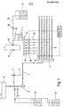
- a source of treatment liquid in the form of a pressurized reservoir 1 containing a lubricant, and a source of carrier liquid, in the form of a tank 2 containing water.
- Water is pumped from the tank 2 to different zones of a bottling line (not shown) wherein lubrication is required. Before the water is sprayed at each zone, the lubricant can be introduced in discrete slugs from the reservoir 1. This is explained in more detail below.
- the water passes from the tank 2 through a water main 3 to a distribution manifold 4.
- a pump 5 In the water main 3 is arranged a pump 5.
- a branch 6 Intermediate the pump 5 and the manifold 4 is a branch 6 which returns to the water main 3 upstream of the pump 5 through a pressure relief valve 7. This allows water to be returned to the tank 2 if necessary.
- a number of pipes 8 branch off from the manifold 4 and each pipe leads to one zone of the bottling line to be treated.
- a control valve 9 which may be a conventional solenoid valve. The operation of the valves 9 is controlled by a central controller.
- Each pipe may have a number of nozzles or branches leading to different nozzles.
- the lubricant is supplied from a reservoir 1.
- An air space lO is present above the lubricant in the reservoir and this space is maintained at an elevated pressure by means of a source of compressed air 11 which is connected to the space 10 via a pressure regulating valve 12 and a vent valve 13 in a pressure line 14.
- the reservoir has level sensors (not shown) and when the sensors detect that the level has fallen to a predetermined level, the vent valve 13 is moved to a position in which the space lO is vented to atmosphere and the reservoir is refilled with lubricant from a supply tank 14 through a line 15 by means of a pump 16.
- the pump 16 is switched off and the pressure in the space 10 is re-introduced.
- the lubricant is supplied from the reservoir 1 through a distribution main 17 with a number of branches 18, one branch for each pipe 8 for the water. There is a T-connection between each pipe 8 and the corresponding branch 18, this connection being downstream of the control valve 9. Upstream of the connection there is arranged in each branch 18 a dosing valve 19 and upstream of that a non-return valve 20.
- the dosing valves which may be shut-off valves, are controlled by the above-mentioned central controller.
- the central controller may be a micro-processor into which the desired open/shut times of valves 9 and 19 are programmed.
- the T-connection between the pipe 8 and branch 18 is illustrated in Fig. 2. It will be noted that the branch 18 intrudes into the pipe 8 at a 90° corner of the pipe.
- the pipe 8 carrying the water flow may be 1 ⁇ 2 inch (13mm) pipe, whereas the branch 18 carrying the lubricant product may be a 1 ⁇ 4 inch (6mm) pipe.
- the branch 18 protrudes % inch (6mm) beyond the corner of the pipe 8, i.e. measurement A in Fig. 2.
- each zone of the bottling line is treated as follows.
- the valve 9 in the water pipe 8 is opened on a cyclical basis, the on and off times being controlled by central controller. While the water is flowing in the pipe 8, the dosing valve 19 is opened for a predetermined amount of time.
- a differential pressure must be maintained between the lubricant in the reservoir 1 and the water in the manifold 4. The length of time the valve 19 is open and the size of the differential pressure determines the amount of lubricant introduced into the water.
- the pressure in the manifold should be constant and it has been found that this pressure is not stable immediately after the valve 9 is opened.
- the lubricant is introduced sometime after the valve 9 is opened.
- the cyclical operation of the valve 9 and the introduction of the lubricant is illustrated in Fig. 3(a), the flow of water being shown in white, the introduction of lubricant being shown black.
- the valve 9 may be opened for 30s every 60s and the valve 19 opened for 2s when the valve 9 has been opened for 5s.
- the lubricant While it is not essential to the invention for the lubricant to remain substantially undiluted in the water pipe, it is advantageous that it dilutes to only a limited extent so that a slug of lubricant/ water solution is produced at each nozzle the concentration of which is substantially higher than the ratio of lubricant to water in the pipe. It has been found that benefits are gained if the peak concentration of the slug at ejection in each zone is at least twice that of the solution formed if the slug mixed completely with the water. Further advantages are gained if the peak concentration is five times, or even ten times, that of the homogeneous solution.
- One method of maintaining the slugs as discrete as possible is to buffer each end of the slug with air. This means that air from a pressurized source is injected into the water stream in pipe 8 immediately before and after the lubricant is injected. Thus, the slug of lubricant, which initially is mixed with the water into which it is injected to form a concentrated solution, is not mixed further down the pipe because it is protected by a bubble at each end.
- the extent to which the slug remains discrete, or conversely the amount in elongates depends inter alia on the flow rate of the water. While the initial length of the slug in pipe 8 is longer the faster the water is flowing, greater elongation occurs later if the flow rate is very low, i.e. in conditions of laminar flow. It has also been found with conventional lubricants that if the water flow is in fact stopped before the slug is injected and then re-started immediately, elongation is great because the lubricant simply tends to adhere to the pipe walls.
- Viscosity also affects the elongation of the slug. It has been found that up to a viscosity of 6,000 to 7,000 centipoise there is a decrease in the rate of elongation, but above this figure increased viscosity tends to increase elongation. The range of 6,000 to 7,000 centipoise appears to be a preferred range.
- the concentration profile of the slug of lubricant product is shown in Figure 4, in dotted lines.
- the length of the slug, shown shaded, is measured from the points at which the concentration of lubricant is substantially zero. As the slug travels along the pipe, its peak concentration tends to fall and the length of the slug increases. Eventually, the different slugs would join up and the concentration would fall to that of a homogeneous solution.
- the lubricant need not be introduced into every "pulse" of water but can be introduced into every second, third or fourth pulse, for example. It has been found that if the slug remains discrete, the lubricant remains on the track or conveyor after it is sprayed for some time and as long as water is continued to be sprayed from time to time the lubricant remains active. This persistency of the lubricant, which means that each zone need only be dosed with lubricant every lO minutes say, also means that the reservoir 1 can be refilled without any interruption in operation since the refilling typically only takes 2-3 minutes. Also the spraying of water alone helps to dissipate any foam which forms on the tracks. Further, the persistency of the lubricant which occurs when a concentrated solution is sprayed on the tracks means that still less expensive lubricant is needed for a given lubrication.
- Precipation can further be avoided by flushing out the pipes 8 with water whenever the system is closed down, for example at the end of a working day.
- the central controller can be programmed to open the valves 9 and flush the pipes whenever the system remains static for a given period of time (say 30 minutes).
- the central controller can be programmed to open each dosing valve 19 automatically for the desired length of time or at the desired frequency according to the demands of each zone.
- a typical volume of lubricant injected into the pipe 8 might be 20cc.
- sequestrant may be present in the reservoir of lubricant or can be separately introduced into the water main 3.
- a reservoir 21 connected to the water main 3 upstream of pump 5.
- the reservoir may contain a biocide which can be fed into the water main 3.
- the lubricant itself need not include any biocide and-so incompatibility of chemicals is not a problem.
- the biocide could be introduced when the conveyors are in use but when the lubricant is not being introduced.
- the biocide could be injected into water main 3 from reservoir 22 when the lubricant reservoir 1 is being refilled and valves 19 are not being operated. By the time the valves 19 are opened again, the biocide will have been flushed through the system and so will not contact the lubricant in the pipework.
- the biocide (product "b") may be dosed into the pipes 8 from a reservoir in the same way as is the lubricant (product "a”).
- the biocide is introduced into the pulses of water into which lubricant was not introduced so that as long as the slugs of lubricant and biocide remained discrete incompatibility of chemical products is again not a problem. Further, the biocidal action of the chemical in the pipes 8 is improved if it passes down the pipe as a concentrated slug.
- the products may be dosed alternately into every fourth or second water pulse.
- Fig. 1 is also illustrated another reservoir 23 connected to the water main 3 upstream of the manifold 4.
- This reservoir may contain a corrosion inhibitor which can be introduced in the same manner as the biocide described above.
- lubricants examples include soaps, phosphate esters, amine salts, amphoteric or quaternary slats.
- Detergents such as non-ionic or anionic amphoteric detergents, may be added, as may sequestrants such as polycarboxylic acids, phosphonates, polyphosphates, polyacrylates. Solvents and hydrotropes, such as alcohols and sulphonic acids, may further be added.
- the following table shows the treatment of a number of zones of a bottling line with a lubricant. Each zone has a number of different nozzles. The water flows for so many seconds out of every 60s and the lubricant is introduced into every n th pulse of water. The differential pressure is 2 bar. The injection point is as illustrated in Fig. 2.
- the amount 6f lubricant fed to each zone can be individually controlled so that over-lubrication or under-lubrication does not occur. Further, for the same levels of cleanness and lubrication as compared with a conventional system, less lubricant overall is used.
Abstract
Description
- This invention relates to a method and apparatus for treating a plurality of zones of a processing line with a liquid, this liquid comprising a treatment liquid and a carrier liquid. One particular application of the invention is in the distribution of a lubricant to surfaces which require lubrication, and, more particularly, the distribution of lubricant to conveyors or tracks (hereinafter referred to simply as "tracks") along which bottles or cans are slidably transported. In what follows, the present invention will be described more particularly with reference to this application.
- In canning and bottling lines large numbers of cans or bottles are conventionally transported using tracks of stainless steel (or other material). The cans or bottles slide along these tracks and it is necessary to supply to the tracks a lubricating material to reduce friction and also to afford some cleaning action. Such materials are usually water-soluble or water-dispersible and comprise an active lubricating agent, for example a soap, and optionally other components, for example, detergents, solvents (e.g. water or non-ionic solvent), and water softening and conditioning agents.
- Canning and bottling lines typically have up to 50 tracks, and the diluted lubricant is applied to the tracks by a spray system, the spray nozzles being fed by a pipework system from a central point. At the central point there is typically a dilution device which takes neat chemical product and dilutes this into, say, a hundred parts of water. The resulting solution is pumped through the pipework system to the spray nozzles. The arrangement just described is well established and is used on a worldwide basis, but has two main deficiencies:
- (1) Certain parts of a canning or bottling track need more lubricating and cleaning than others. In particular, in a bottling line which uses bottles which have already been used and are returned dirty by the user, the bottles at the in-feed end have a large amount of soil on them which tends to be transferred to the track. Also, there is liable to be spillage of the product with which the bottles or cans are being filled at the filling station, and the spilt product mostly ends up on the track. Accordingly, additional lubrication is desirable at the filling station and separately at the dirty bottle infeed. The conventional lubrication system allows for only one overall concentration, i.e. the concentration is the same at all points. This concentration must be high enough to cope with the dirtiest part of the line and so in the cleaner parts there is over-lubrication. Since the lubricant is typically a soap-like chemical, over-lubrication leads to excessive foaming. Excess foam is detrimental, for example because it can trigger off optical scanning instruments and if spilt on the floor can lead to a safety hazard. Further, over-lubrication is expensive because lubricant is wasted.
- (2) The main constituent of the track lubricant, i.e. the soap or the like, precipitates lime soaps in the presence of hard water, i.e. when mixed with hard water in the diluting system. These precipitates block the spraying nozzles and are generally detrimental to the operation. To overcome this problem it is known to add a sequestering agent to stop precipitation. However, the sequestrant is typically an expensive chemical.
- To the best of the applicants' knowledge, the only attempt which has been made to overcome the above disadvantages is that described in European Patent Application no. 0079152 (Chemed Corporation). This application discloses an arrangement where the lubricant and the water are piped separately to different points along a conveyor. This allows the lubricant to be individually metered at each point and further hard water precipitation is avoided because the lubricant and the water are not mixed in the pipework itself. However, these advantages are only achieved at the great expense of providing two separate sets of pipework and nozzles, one for the lubricant and one for the water.
- According to the present invention there is provided a method of treating a plurality of zones of a processing line with a liquid, the liquid comprising a treatment liquid and a carrier liquid, wherein the treatment liquid is introduced into pipes conveying the carrier liquid to each zone-as discrete slugs, and wherein the volume of each slug is selectively variable or wherein each slug may be introduced into the pipes at a selectively variable frequency.
- The invention also provides an apparatus for treating a plurality of zones in a processing line with a liquid, the liquid comprising a treatment liquid and a carrier liquid, the apparatus comprising:
- a source of treatment liquid;
- a source of carrier liquid;
- a plurality of pipes conveying the carrier
- A "discrete slug" is formed when the treatment liquid is introduced into a carrier liquid pipe for a limited amount of time during which the carrier liquid may either continue to flow or may be stopped.
- It is preferable if the slug of treatment liquid remains to some extent discrete until it is ejected from the pipe at the zone to be treated, i.e. it does not mix homogeneously with the carrier fluid.
- The first advantage of the invention is that the amount of treatment liquid, e.g. lubricant, can be chosen to suit the demands of each individual zone of the processing line by simply changing the size of the slugs or the frequency of their introduction and without the need of a duplicate piping system.
- Further advantages will become apparent from the following detailed description of a preferred embodiment of the invention, referring to the drawings, in which:
- Fig. 1 is a schematic representation of a method and apparatus for treating a plurality of zones of a processing line with a liquid;
- Fig. 2 is a view showing the introduction of the treatment liquid;
- Fig. 3(a) to (d) are diagrams showing the flow carrier liquid with time and the introduction of treatment liquid; and
- Fig. 4 is a flow diagram showing the elongation of the slug of treatment liquid.
- In Fig. 1 are shown a source of treatment liquid, in the form of a pressurized reservoir 1 containing a lubricant, and a source of carrier liquid, in the form of a
tank 2 containing water. - Water is pumped from the
tank 2 to different zones of a bottling line (not shown) wherein lubrication is required. Before the water is sprayed at each zone, the lubricant can be introduced in discrete slugs from the reservoir 1. This is explained in more detail below. - The water passes from the
tank 2 through a water main 3 to a distribution manifold 4. In the water main 3 is arranged a pump 5. Intermediate the pump 5 and the manifold 4 is a branch 6 which returns to the water main 3 upstream of the pump 5 through a pressure relief valve 7. This allows water to be returned to thetank 2 if necessary. - A number of
pipes 8 branch off from the manifold 4 and each pipe leads to one zone of the bottling line to be treated. In eachpipe 8 is arranged acontrol valve 9, which may be a conventional solenoid valve. The operation of thevalves 9 is controlled by a central controller. Each pipe may have a number of nozzles or branches leading to different nozzles. - As mentioned above, the lubricant is supplied from a reservoir 1. An air space lO is present above the lubricant in the reservoir and this space is maintained at an elevated pressure by means of a source of compressed
air 11 which is connected to thespace 10 via apressure regulating valve 12 and avent valve 13 in apressure line 14. The reservoir has level sensors (not shown) and when the sensors detect that the level has fallen to a predetermined level, thevent valve 13 is moved to a position in which the space lO is vented to atmosphere and the reservoir is refilled with lubricant from asupply tank 14 through aline 15 by means of apump 16. When the sensors detect that a given level has been reached in the reservoir, thepump 16 is switched off and the pressure in thespace 10 is re-introduced. - The lubricant is supplied from the reservoir 1 through a distribution main 17 with a number of
branches 18, one branch for eachpipe 8 for the water. There is a T-connection between eachpipe 8 and thecorresponding branch 18, this connection being downstream of thecontrol valve 9. Upstream of the connection there is arranged in each branch 18 adosing valve 19 and upstream of that anon-return valve 20. The dosing valves, which may be shut-off valves, are controlled by the above-mentioned central controller. - The central controller may be a micro-processor into which the desired open/shut times of
valves - The T-connection between the
pipe 8 andbranch 18 is illustrated in Fig. 2. It will be noted that thebranch 18 intrudes into thepipe 8 at a 90° corner of the pipe. Thepipe 8 carrying the water flow may be ½ inch (13mm) pipe, whereas thebranch 18 carrying the lubricant product may be a ¼ inch (6mm) pipe. Thebranch 18 protrudes % inch (6mm) beyond the corner of thepipe 8, i.e. measurement A in Fig. 2. - In practice, each zone of the bottling line is treated as follows. The
valve 9 in thewater pipe 8 is opened on a cyclical basis, the on and off times being controlled by central controller. While the water is flowing in thepipe 8, thedosing valve 19 is opened for a predetermined amount of time. To ensure that the lubricant is injected into the-water stream, a differential pressure must be maintained between the lubricant in the reservoir 1 and the water in the manifold 4. The length of time thevalve 19 is open and the size of the differential pressure determines the amount of lubricant introduced into the water. To accurately control the amount of lubricant introduced, the pressure in the manifold should be constant and it has been found that this pressure is not stable immediately after thevalve 9 is opened. Accordingly, the lubricant is introduced sometime after thevalve 9 is opened. The cyclical operation of thevalve 9 and the introduction of the lubricant is illustrated in Fig. 3(a), the flow of water being shown in white, the introduction of lubricant being shown black. At a differential pressure of 2 bar thevalve 9 may be opened for 30s every 60s and thevalve 19 opened for 2s when thevalve 9 has been opened for 5s. - It should now be explained what happens to the lubricant after it is introduced into the water. It has been found most advantageous from a lubricating and cleaning point of view for a concentrated solution of the lubricant to be produced quickly in the
pipe 8, rather than pure lubricant to be transported "wedged" between sections of water. To dilute the lubricant at the point of injection to, say, a lO or 20% solution, some turbulence within the pipe is needed. This is achieved by injecting the lubricant into the middle of the water stream, as shown in Fig. 2. Also, this tends to keep the lubricant away from the walls of the pipe which prevents the introduced lubricant from elongating excessively by sticking to the pipe walls. - It has been found that by transporting a diluted solution of lubricant along
the_pipe 8, rather than a "wedge" of pure lubricant, the lubricant divides itself substantially equally between the nozzles of each zone which branch off thepipe 8. - While it is not essential to the invention for the lubricant to remain substantially undiluted in the water pipe, it is advantageous that it dilutes to only a limited extent so that a slug of lubricant/ water solution is produced at each nozzle the concentration of which is substantially higher than the ratio of lubricant to water in the pipe. It has been found that benefits are gained if the peak concentration of the slug at ejection in each zone is at least twice that of the solution formed if the slug mixed completely with the water. Further advantages are gained if the peak concentration is five times, or even ten times, that of the homogeneous solution.
- One method of maintaining the slugs as discrete as possible is to buffer each end of the slug with air. This means that air from a pressurized source is injected into the water stream in
pipe 8 immediately before and after the lubricant is injected. Thus, the slug of lubricant, which initially is mixed with the water into which it is injected to form a concentrated solution, is not mixed further down the pipe because it is protected by a bubble at each end. - Further, it has been found that the extent to which the slug remains discrete, or conversely the amount in elongates, depends inter alia on the flow rate of the water. While the initial length of the slug in
pipe 8 is longer the faster the water is flowing, greater elongation occurs later if the flow rate is very low, i.e. in conditions of laminar flow. It has also been found with conventional lubricants that if the water flow is in fact stopped before the slug is injected and then re-started immediately, elongation is great because the lubricant simply tends to adhere to the pipe walls. - Viscosity also affects the elongation of the slug. It has been found that up to a viscosity of 6,000 to 7,000 centipoise there is a decrease in the rate of elongation, but above this figure increased viscosity tends to increase elongation. The range of 6,000 to 7,000 centipoise appears to be a preferred range.
- Of course, the length of pipe along which the slug travels also affects the elongation or dilution of the slug. The longer the pipe, the closer the slug approaches an homogeneous solution.
- The concentration profile of the slug of lubricant product is shown in Figure 4, in dotted lines. The length of the slug, shown shaded, is measured from the points at which the concentration of lubricant is substantially zero. As the slug travels along the pipe, its peak concentration tends to fall and the length of the slug increases. Eventually, the different slugs would join up and the concentration would fall to that of a homogeneous solution.
- As can be seen from Fig. 3(b) the lubricant need not be introduced into every "pulse" of water but can be introduced into every second, third or fourth pulse, for example. It has been found that if the slug remains discrete, the lubricant remains on the track or conveyor after it is sprayed for some time and as long as water is continued to be sprayed from time to time the lubricant remains active. This persistency of the lubricant, which means that each zone need only be dosed with lubricant every lO minutes say, also means that the reservoir 1 can be refilled without any interruption in operation since the refilling typically only takes 2-3 minutes. Also the spraying of water alone helps to dissipate any foam which forms on the tracks. Further, the persistency of the lubricant which occurs when a concentrated solution is sprayed on the tracks means that still less expensive lubricant is needed for a given lubrication.
- Because the pipes are often full of pure water with no lubricant and because the slugs of lubricant can remain discrete throughout the pipework, it is clear that the extent to which the lubricant is present in the pipes together with water can be much reduced as compared to the conventional system where a dilute solution is used throughout. Accordingly, precipitation of hard water salts is substantially reduced. This effectively prevents blockage of nozzles by precipitation of hard water salts and also means that chemicals with high lubricating and cleaning properties but limited hard water tolerance can be used.
- Precipation can further be avoided by flushing out the
pipes 8 with water whenever the system is closed down, for example at the end of a working day. The central controller can be programmed to open thevalves 9 and flush the pipes whenever the system remains static for a given period of time (say 30 minutes). - Returning to the primary advantage of the invention over the conventional system, namely the selection of the required amount of lubricant for each zone of the bottling line, the central controller can be programmed to open each
dosing valve 19 automatically for the desired length of time or at the desired frequency according to the demands of each zone. A typical volume of lubricant injected into thepipe 8 might be 20cc. - Because usage of lubricant is more effectively controlled by the invention, not only is less lubricant necessary than in the conventional system, but also different, cheaper chemicals with higher foaming properties may be used since less foaming due to over-lubrication will occur.
- Again, because there is less lubricant in the system (and indeed because there is less contact between water and lubricant as explained above) less expensive sequestrant need be used to sequester the metal ions which cause the precipitation in hard water. The sequestrant may be present in the reservoir of lubricant or can be separately introduced into the water main 3.
- Also shown in Fig. 1 is a
reservoir 21 connected to the water main 3 upstream of pump 5. The reservoir may contain a biocide which can be fed into the water main 3. With this system, the pipework and tracks or conveyors can be treated with the biocide over-night when the lubricant is not being used. The lubricant itself need not include any biocide and-so incompatibility of chemicals is not a problem. As an alternative, the biocide could be introduced when the conveyors are in use but when the lubricant is not being introduced. Thus, for example, the biocide could be injected into water main 3 fromreservoir 22 when the lubricant reservoir 1 is being refilled andvalves 19 are not being operated. By the time thevalves 19 are opened again, the biocide will have been flushed through the system and so will not contact the lubricant in the pipework. - In another embodiment, illustrated in Figs. 3(c) and (d), the biocide (product "b") may be dosed into the
pipes 8 from a reservoir in the same way as is the lubricant (product "a"). The biocide is introduced into the pulses of water into which lubricant was not introduced so that as long as the slugs of lubricant and biocide remained discrete incompatibility of chemical products is again not a problem. Further, the biocidal action of the chemical in thepipes 8 is improved if it passes down the pipe as a concentrated slug. As shown in the figures, the products may be dosed alternately into every fourth or second water pulse. - In Fig. 1 is also illustrated another reservoir 23 connected to the water main 3 upstream of the manifold 4. This reservoir may contain a corrosion inhibitor which can be introduced in the same manner as the biocide described above.
- Examples of lubricants are soaps, phosphate esters, amine salts, amphoteric or quaternary slats. Detergents, such as non-ionic or anionic amphoteric detergents, may be added, as may sequestrants such as polycarboxylic acids, phosphonates, polyphosphates, polyacrylates. Solvents and hydrotropes, such as alcohols and sulphonic acids, may further be added.
- The following table shows the treatment of a number of zones of a bottling line with a lubricant. Each zone has a number of different nozzles. The water flows for so many seconds out of every 60s and the lubricant is introduced into every nth pulse of water. The differential pressure is 2 bar. The injection point is as illustrated in Fig. 2.
- It can be seen that the amount 6f lubricant fed to each zone can be individually controlled so that over-lubrication or under-lubrication does not occur. Further, for the same levels of cleanness and lubrication as compared with a conventional system, less lubricant overall is used.
-

liquid to each zone; and
means for introducing the treatment liquid into each pipe in discrete slugs of a selectively variable volume or at a selectively variable frequency.
Claims (17)
means (19) for introducing the treatment liquid into each pipe in discrete slugs of a selectively variable volume or at a selectively variable frequency.
Priority Applications (1)
| Application Number | Priority Date | Filing Date | Title |
|---|---|---|---|
| AT85305186T ATE39990T1 (en) | 1984-07-24 | 1985-07-22 | PROCEDURE AND ARRANGEMENT FOR TREATMENT OF A MAJORITY OF THE ZONES OF A LINE OF PROCEDURE. |
Applications Claiming Priority (2)
| Application Number | Priority Date | Filing Date | Title |
|---|---|---|---|
| GB8418778 | 1984-07-24 | ||
| GB848418778A GB8418778D0 (en) | 1984-07-24 | 1984-07-24 | Introducing material into fluid |
Publications (3)
| Publication Number | Publication Date |
|---|---|
| EP0169723A2 true EP0169723A2 (en) | 1986-01-29 |
| EP0169723A3 EP0169723A3 (en) | 1987-02-04 |
| EP0169723B1 EP0169723B1 (en) | 1989-01-11 |
Family
ID=10564326
Family Applications (1)
| Application Number | Title | Priority Date | Filing Date |
|---|---|---|---|
| EP85305186A Expired EP0169723B1 (en) | 1984-07-24 | 1985-07-22 | Method and apparatus for treating a plurality of zones of a processing line |
Country Status (10)
| Country | Link |
|---|---|
| US (1) | US4627457A (en) |
| EP (1) | EP0169723B1 (en) |
| AT (1) | ATE39990T1 (en) |
| AU (1) | AU573014B2 (en) |
| BR (1) | BR8503477A (en) |
| CA (1) | CA1249775A (en) |
| DE (1) | DE3567527D1 (en) |
| DK (1) | DK337385A (en) |
| ES (1) | ES8705259A1 (en) |
| GB (2) | GB8418778D0 (en) |
Cited By (4)
| Publication number | Priority date | Publication date | Assignee | Title |
|---|---|---|---|---|
| FR2620903A1 (en) * | 1987-09-25 | 1989-03-31 | Henkel France | Method and installation for cleaning movable transporters in canneries |
| WO1995008498A1 (en) * | 1993-09-23 | 1995-03-30 | Henkel-Ecolab Gmbh & Co. Ohg | Installation and process for lubricating, cleaning and/or disinfecting conveyor belts |
| WO1995008499A1 (en) * | 1993-09-23 | 1995-03-30 | Henkel-Ecolab Gmbh & Co. Ohg | Process for lubricating, cleaning and/or disinfecting, especially by means of a fully automatic central belt lubrication installation |
| US9328872B2 (en) | 2013-12-18 | 2016-05-03 | Ge Oil & Gas Uk Limited | Multiple chemical supply line |
Families Citing this family (21)
| Publication number | Priority date | Publication date | Assignee | Title |
|---|---|---|---|---|
| US5137694A (en) * | 1985-05-08 | 1992-08-11 | Ecolab Inc. | Industrial solid detergent dispenser and cleaning system |
| DE4107478C1 (en) * | 1991-03-08 | 1992-05-21 | Then Maschinen- Und Apparatebau Gmbh, 7170 Schwaebisch Hall, De | |
| US5247957A (en) * | 1991-10-24 | 1993-09-28 | H. B. Fuller Company | Modular lubrication multiple concentration control apparatus |
| DE4332375A1 (en) * | 1993-09-23 | 1995-03-30 | Lang Apparatebau Gmbh | System and method for lubricating, cleaning and / or disinfecting conveyor belts or chains |
| US5372243A (en) * | 1994-02-07 | 1994-12-13 | Pure-Chem Products Company, Inc. | Apparatus and method for cleaning conveyors |
| US5590686A (en) * | 1995-05-02 | 1997-01-07 | Dober Chemical Corp. | Liquid delivery systems |
| US5772003A (en) * | 1995-11-22 | 1998-06-30 | Bio-Cide International, Inc. | Automatic lubrication injection sanitization system |
| US6463611B1 (en) | 1999-04-02 | 2002-10-15 | Ecolab, Inc. | Apparatus for dispensing incompatible chemicals to a common utilization point |
| ES2386297T3 (en) | 1999-07-22 | 2012-08-16 | Diversey, Inc. | Use of lubricant composition to lubricate a conveyor belt |
| US6495494B1 (en) * | 2000-06-16 | 2002-12-17 | Ecolab Inc. | Conveyor lubricant and method for transporting articles on a conveyor system |
| US6427826B1 (en) | 1999-11-17 | 2002-08-06 | Ecolab Inc. | Container, such as a food or beverage container, lubrication method |
| US6302263B1 (en) * | 1999-10-08 | 2001-10-16 | Ecolab, Inc. | Apparatus and method for the controlled lubrication and cleaning of conveyors |
| US7364033B2 (en) * | 1999-11-17 | 2008-04-29 | Ecolab Inc. | Container, such as a food or beverage container, lubrication method |
| US6651803B2 (en) | 2000-02-10 | 2003-11-25 | Tyson Fresh Meats, Inc. | Automated conveyor cleaning system |
| US6360874B1 (en) * | 2000-02-10 | 2002-03-26 | Ibp, Inc. | Automated conveyor cleaning system |
| US6698551B2 (en) * | 2001-04-10 | 2004-03-02 | Lincoln Industrial Corporation | Modular lubricating system and injector |
| JP2007327542A (en) * | 2006-06-07 | 2007-12-20 | Surpass Kogyo Kk | Fluid apparatus unit structure |
| SE530447C2 (en) * | 2006-10-25 | 2008-06-10 | Scania Cv Abp | Lubrication device, gearbox and ways to lubricate a gearbox |
| WO2010111639A1 (en) * | 2009-03-26 | 2010-09-30 | Resonant Biosciences, Llc | Apparatus and method for applying a biocide to microorganisms during a conditioning, propagation and/or fermentation process |
| US8794385B2 (en) * | 2010-07-07 | 2014-08-05 | General Electric Company | Lube injection for free solids flow through a pump |
| DE102015100762A1 (en) * | 2015-01-20 | 2016-07-21 | Infineon Technologies Ag | Container switching device and method for monitoring a fluid rate |
Citations (9)
| Publication number | Priority date | Publication date | Assignee | Title |
|---|---|---|---|---|
| GB920761A (en) * | 1958-04-30 | 1963-03-13 | Auto Research Corp | Lubrication |
| US4022512A (en) * | 1976-01-26 | 1977-05-10 | Whitlock, Inc. | Pneumatic conveyors |
| FR2386342A1 (en) * | 1977-04-06 | 1978-11-03 | Politechnika Gdanska | Programmed mixing of 3 liquids - for chromatography with crosses, two=way and three=way valves controlled by tape reader |
| GB2026729A (en) * | 1978-07-20 | 1980-02-06 | Draegerwerk Ag | Apparatus and method for the controlled metering and mixing of two or more gases |
| US4226325A (en) * | 1979-03-15 | 1980-10-07 | Mcgraw-Edison Company | Conveyor lubricating and washing apparatus |
| US4262776A (en) * | 1978-09-13 | 1981-04-21 | H. B. Fuller Company | Conveyor lubricating system |
| CH626972A5 (en) * | 1977-10-20 | 1981-12-15 | Eschler Max Paul | Method for the lubrication of a number of lubrication points and a metering device for carrying out the method |
| GB2081820A (en) * | 1980-08-07 | 1982-02-24 | Madison Kipp Corp | Apparatus and method for dispensing fluids |
| EP0079152A1 (en) * | 1981-11-05 | 1983-05-18 | Chemed Corporation | Improved lubrication of conveyor chains |
Family Cites Families (4)
| Publication number | Priority date | Publication date | Assignee | Title |
|---|---|---|---|---|
| US2706254A (en) * | 1951-07-12 | 1955-04-12 | California Research Corp | Operation of pipelines |
| US3726297A (en) * | 1971-04-14 | 1973-04-10 | Technicon Instr | Method and device for introducing for mixing a first liquid into a second liquid |
| US4149624A (en) * | 1976-12-15 | 1979-04-17 | United States Steel Corporation | Method and apparatus for promoting release of fines |
| US4196748A (en) * | 1977-12-16 | 1980-04-08 | Stauffer Chemical Company | Multiple strength fluid distribution apparatus |
-
1984
- 1984-07-24 GB GB848418778A patent/GB8418778D0/en active Pending
-
1985
- 1985-07-18 US US06/756,757 patent/US4627457A/en not_active Expired - Lifetime
- 1985-07-22 AT AT85305186T patent/ATE39990T1/en active
- 1985-07-22 EP EP85305186A patent/EP0169723B1/en not_active Expired
- 1985-07-22 BR BR8503477A patent/BR8503477A/en not_active IP Right Cessation
- 1985-07-22 GB GB08518504A patent/GB2164100B/en not_active Expired
- 1985-07-22 DE DE8585305186T patent/DE3567527D1/en not_active Expired
- 1985-07-23 ES ES545491A patent/ES8705259A1/en not_active Expired
- 1985-07-23 AU AU45258/85A patent/AU573014B2/en not_active Ceased
- 1985-07-24 CA CA000487374A patent/CA1249775A/en not_active Expired
- 1985-07-24 DK DK337385A patent/DK337385A/en not_active Application Discontinuation
Patent Citations (9)
| Publication number | Priority date | Publication date | Assignee | Title |
|---|---|---|---|---|
| GB920761A (en) * | 1958-04-30 | 1963-03-13 | Auto Research Corp | Lubrication |
| US4022512A (en) * | 1976-01-26 | 1977-05-10 | Whitlock, Inc. | Pneumatic conveyors |
| FR2386342A1 (en) * | 1977-04-06 | 1978-11-03 | Politechnika Gdanska | Programmed mixing of 3 liquids - for chromatography with crosses, two=way and three=way valves controlled by tape reader |
| CH626972A5 (en) * | 1977-10-20 | 1981-12-15 | Eschler Max Paul | Method for the lubrication of a number of lubrication points and a metering device for carrying out the method |
| GB2026729A (en) * | 1978-07-20 | 1980-02-06 | Draegerwerk Ag | Apparatus and method for the controlled metering and mixing of two or more gases |
| US4262776A (en) * | 1978-09-13 | 1981-04-21 | H. B. Fuller Company | Conveyor lubricating system |
| US4226325A (en) * | 1979-03-15 | 1980-10-07 | Mcgraw-Edison Company | Conveyor lubricating and washing apparatus |
| GB2081820A (en) * | 1980-08-07 | 1982-02-24 | Madison Kipp Corp | Apparatus and method for dispensing fluids |
| EP0079152A1 (en) * | 1981-11-05 | 1983-05-18 | Chemed Corporation | Improved lubrication of conveyor chains |
Cited By (5)
| Publication number | Priority date | Publication date | Assignee | Title |
|---|---|---|---|---|
| FR2620903A1 (en) * | 1987-09-25 | 1989-03-31 | Henkel France | Method and installation for cleaning movable transporters in canneries |
| WO1995008498A1 (en) * | 1993-09-23 | 1995-03-30 | Henkel-Ecolab Gmbh & Co. Ohg | Installation and process for lubricating, cleaning and/or disinfecting conveyor belts |
| WO1995008499A1 (en) * | 1993-09-23 | 1995-03-30 | Henkel-Ecolab Gmbh & Co. Ohg | Process for lubricating, cleaning and/or disinfecting, especially by means of a fully automatic central belt lubrication installation |
| US5873946A (en) * | 1993-09-23 | 1999-02-23 | Henkel-Ecolab Gmbh & Co. Ohg | Installation and a process for lubricating, cleaning and/or disinfecting conveyor belts |
| US9328872B2 (en) | 2013-12-18 | 2016-05-03 | Ge Oil & Gas Uk Limited | Multiple chemical supply line |
Also Published As
| Publication number | Publication date |
|---|---|
| EP0169723A3 (en) | 1987-02-04 |
| CA1249775A (en) | 1989-02-07 |
| BR8503477A (en) | 1986-04-15 |
| ATE39990T1 (en) | 1989-01-15 |
| GB8418778D0 (en) | 1984-08-30 |
| US4627457A (en) | 1986-12-09 |
| DK337385D0 (en) | 1985-07-24 |
| EP0169723B1 (en) | 1989-01-11 |
| GB8518504D0 (en) | 1985-08-29 |
| GB2164100B (en) | 1988-03-02 |
| DK337385A (en) | 1986-01-25 |
| AU4525885A (en) | 1986-01-30 |
| DE3567527D1 (en) | 1989-02-16 |
| ES545491A0 (en) | 1987-05-01 |
| GB2164100A (en) | 1986-03-12 |
| ES8705259A1 (en) | 1987-05-01 |
| AU573014B2 (en) | 1988-05-26 |
Similar Documents
| Publication | Publication Date | Title |
|---|---|---|
| EP0169723B1 (en) | Method and apparatus for treating a plurality of zones of a processing line | |
| US5247957A (en) | Modular lubrication multiple concentration control apparatus | |
| US4839067A (en) | Process for lubricating and cleaning of bottle conveyor belts in the beverage industry | |
| US4262776A (en) | Conveyor lubricating system | |
| US6302263B1 (en) | Apparatus and method for the controlled lubrication and cleaning of conveyors | |
| US20030159889A1 (en) | Conveyor and lubricating apparatus, lubricant dispensing device, and method for applying lubricant to conveyor | |
| US7601053B2 (en) | Ozone-based conveyor cleaning system | |
| JP5642933B2 (en) | Method for lubricating container passages along a conveyor | |
| EP0720579B1 (en) | Installation and process for lubricating, cleaning and/or disinfecting conveyor belts or chains | |
| DE102007017523A1 (en) | Process for cleaning beverage filling plants | |
| AU709392B2 (en) | System and method for removing residue from a steel product | |
| US5873946A (en) | Installation and a process for lubricating, cleaning and/or disinfecting conveyor belts | |
| US4196748A (en) | Multiple strength fluid distribution apparatus | |
| WO2005014764A1 (en) | Chain lubricants | |
| EP0079152A1 (en) | Improved lubrication of conveyor chains | |
| US5772003A (en) | Automatic lubrication injection sanitization system | |
| US20080272037A1 (en) | Apparatus, products and processes for preventing the occurrence of rust strains resulting from irrigation systems using water containing iron ions | |
| US3753528A (en) | Lubrication system | |
| AU737405B2 (en) | Dispensing device for lubricant composition | |
| KR100211613B1 (en) | Lubrication system for container fabrication ironer | |
| US3554323A (en) | Apparatus for automatic lubrication of chain link conveyors | |
| US20210299708A1 (en) | Methods and systems for online cleaning of beverage fillers | |
| JP2022058055A (en) | Conveyor lubricant composition | |
| DE10127046A1 (en) | Process and system for maintaining the smooth movement of transport chains | |
| ITMI982762A1 (en) | FOAMING EQUIPMENT. |
Legal Events
| Date | Code | Title | Description |
|---|---|---|---|
| PUAI | Public reference made under article 153(3) epc to a published international application that has entered the european phase |
Free format text: ORIGINAL CODE: 0009012 |
|
| AK | Designated contracting states |
Designated state(s): AT BE DE FR GB IT NL SE |
|
| PUAL | Search report despatched |
Free format text: ORIGINAL CODE: 0009013 |
|
| AK | Designated contracting states |
Kind code of ref document: A3 Designated state(s): AT BE DE FR GB IT NL SE |
|
| 17P | Request for examination filed |
Effective date: 19870409 |
|
| 17Q | First examination report despatched |
Effective date: 19880322 |
|
| RBV | Designated contracting states (corrected) |
Designated state(s): AT BE DE FR IT NL SE |
|
| GRAA | (expected) grant |
Free format text: ORIGINAL CODE: 0009210 |
|
| AK | Designated contracting states |
Kind code of ref document: B1 Designated state(s): AT BE DE FR IT NL SE |
|
| REF | Corresponds to: |
Ref document number: 39990 Country of ref document: AT Date of ref document: 19890115 Kind code of ref document: T |
|
| REF | Corresponds to: |
Ref document number: 3567527 Country of ref document: DE Date of ref document: 19890216 |
|
| ITF | It: translation for a ep patent filed |
Owner name: SOCIETA' ITALIANA BREVETTI S.P.A. |
|
| ET | Fr: translation filed | ||
| PLBI | Opposition filed |
Free format text: ORIGINAL CODE: 0009260 |
|
| 26 | Opposition filed |
Opponent name: ECOLAB INC. Effective date: 19891011 |
|
| NLR1 | Nl: opposition has been filed with the epo |
Opponent name: ECOLAB INC. |
|
| PGFP | Annual fee paid to national office [announced via postgrant information from national office to epo] |
Ref country code: AT Payment date: 19910711 Year of fee payment: 7 |
|
| PGFP | Annual fee paid to national office [announced via postgrant information from national office to epo] |
Ref country code: SE Payment date: 19910719 Year of fee payment: 7 |
|
| PGFP | Annual fee paid to national office [announced via postgrant information from national office to epo] |
Ref country code: FR Payment date: 19910721 Year of fee payment: 7 |
|
| ITTA | It: last paid annual fee | ||
| PGFP | Annual fee paid to national office [announced via postgrant information from national office to epo] |
Ref country code: NL Payment date: 19910731 Year of fee payment: 7 |
|
| PGFP | Annual fee paid to national office [announced via postgrant information from national office to epo] |
Ref country code: DE Payment date: 19910830 Year of fee payment: 7 |
|
| PGFP | Annual fee paid to national office [announced via postgrant information from national office to epo] |
Ref country code: BE Payment date: 19910904 Year of fee payment: 7 |
|
| PG25 | Lapsed in a contracting state [announced via postgrant information from national office to epo] |
Ref country code: SE Effective date: 19920723 |
|
| PG25 | Lapsed in a contracting state [announced via postgrant information from national office to epo] |
Ref country code: BE Effective date: 19920731 |
|
| RDAG | Patent revoked |
Free format text: ORIGINAL CODE: 0009271 |
|
| STAA | Information on the status of an ep patent application or granted ep patent |
Free format text: STATUS: PATENT REVOKED |
|
| BERE | Be: lapsed |
Owner name: DIVERSEY ENGINEERING (EUROPE) LTD Effective date: 19920731 |
|
| 27W | Patent revoked |
Effective date: 19921006 |
|
| NLV4 | Nl: lapsed or anulled due to non-payment of the annual fee | ||
| EUG | Se: european patent has lapsed |
Ref document number: 85305186.0 Effective date: 19930204 |
|
| APAH | Appeal reference modified |
Free format text: ORIGINAL CODE: EPIDOSCREFNO |
|
| PLAB | Opposition data, opponent's data or that of the opponent's representative modified |
Free format text: ORIGINAL CODE: 0009299OPPO |