EP0079103B1 - Baggervorrichtung - Google Patents
Baggervorrichtung Download PDFInfo
- Publication number
- EP0079103B1 EP0079103B1 EP82201379A EP82201379A EP0079103B1 EP 0079103 B1 EP0079103 B1 EP 0079103B1 EP 82201379 A EP82201379 A EP 82201379A EP 82201379 A EP82201379 A EP 82201379A EP 0079103 B1 EP0079103 B1 EP 0079103B1
- Authority
- EP
- European Patent Office
- Prior art keywords
- belt
- tube
- blades
- frame
- downwards
- Prior art date
- Legal status (The legal status is an assumption and is not a legal conclusion. Google has not performed a legal analysis and makes no representation as to the accuracy of the status listed.)
- Expired
Links
- 239000000463 material Substances 0.000 claims description 20
- 238000005192 partition Methods 0.000 claims description 14
- XLYOFNOQVPJJNP-UHFFFAOYSA-N water Substances O XLYOFNOQVPJJNP-UHFFFAOYSA-N 0.000 claims description 13
- 239000002689 soil Substances 0.000 claims description 2
- 238000010276 construction Methods 0.000 description 4
- 230000008901 benefit Effects 0.000 description 3
- 239000007788 liquid Substances 0.000 description 2
- 239000000203 mixture Substances 0.000 description 2
- 230000004048 modification Effects 0.000 description 2
- 238000012986 modification Methods 0.000 description 2
- 239000010802 sludge Substances 0.000 description 2
- 239000004575 stone Substances 0.000 description 2
- 229910000831 Steel Inorganic materials 0.000 description 1
- 239000004927 clay Substances 0.000 description 1
- 230000003247 decreasing effect Effects 0.000 description 1
- 238000001035 drying Methods 0.000 description 1
- 239000002245 particle Substances 0.000 description 1
- 230000002787 reinforcement Effects 0.000 description 1
- 239000004576 sand Substances 0.000 description 1
- 239000010959 steel Substances 0.000 description 1
Images
Classifications
-
- B—PERFORMING OPERATIONS; TRANSPORTING
- B65—CONVEYING; PACKING; STORING; HANDLING THIN OR FILAMENTARY MATERIAL
- B65G—TRANSPORT OR STORAGE DEVICES, e.g. CONVEYORS FOR LOADING OR TIPPING, SHOP CONVEYOR SYSTEMS OR PNEUMATIC TUBE CONVEYORS
- B65G19/00—Conveyors comprising an impeller or a series of impellers carried by an endless traction element and arranged to move articles or materials over a supporting surface or underlying material, e.g. endless scraper conveyors
- B65G19/14—Conveyors comprising an impeller or a series of impellers carried by an endless traction element and arranged to move articles or materials over a supporting surface or underlying material, e.g. endless scraper conveyors for moving bulk material in closed conduits, e.g. tubes
-
- E—FIXED CONSTRUCTIONS
- E02—HYDRAULIC ENGINEERING; FOUNDATIONS; SOIL SHIFTING
- E02F—DREDGING; SOIL-SHIFTING
- E02F3/00—Dredgers; Soil-shifting machines
- E02F3/04—Dredgers; Soil-shifting machines mechanically-driven
- E02F3/08—Dredgers; Soil-shifting machines mechanically-driven with digging elements on an endless chain
- E02F3/081—Dredgers; Soil-shifting machines mechanically-driven with digging elements on an endless chain mounted on floating substructures
-
- E—FIXED CONSTRUCTIONS
- E02—HYDRAULIC ENGINEERING; FOUNDATIONS; SOIL SHIFTING
- E02F—DREDGING; SOIL-SHIFTING
- E02F3/00—Dredgers; Soil-shifting machines
- E02F3/04—Dredgers; Soil-shifting machines mechanically-driven
- E02F3/08—Dredgers; Soil-shifting machines mechanically-driven with digging elements on an endless chain
- E02F3/12—Component parts, e.g. bucket troughs
- E02F3/14—Buckets; Chains; Guides for buckets or chains; Drives for chains
- E02F3/143—Buckets; Chains; Guides for buckets or chains; Drives for chains chains; chain links; scraper chains
-
- E—FIXED CONSTRUCTIONS
- E02—HYDRAULIC ENGINEERING; FOUNDATIONS; SOIL SHIFTING
- E02F—DREDGING; SOIL-SHIFTING
- E02F3/00—Dredgers; Soil-shifting machines
- E02F3/04—Dredgers; Soil-shifting machines mechanically-driven
- E02F3/08—Dredgers; Soil-shifting machines mechanically-driven with digging elements on an endless chain
- E02F3/12—Component parts, e.g. bucket troughs
- E02F3/14—Buckets; Chains; Guides for buckets or chains; Drives for chains
- E02F3/146—Buckets; Chains; Guides for buckets or chains; Drives for chains guides for chains or buckets, e.g. for buckets movable relative to chains
Definitions
- the invention relates to a dredging apparatus comprising a floating device and a frame suspended adjustably therein and having reversing wheels for an endless conveying member provided with means for loosening and feeding the soil material upwards, said apparatus further being provided with means for receiving the material discharged from said members (known, for example from NL-A-6812058).
- Such a dredging apparatus is known in the form of a bucket ladder dredger.
- Such dredgers have the advantage that the amount of energy per m 3 of dredged material is relatively low in comparison with suction dredgers sucking a mixture of ground and water, respectively suction dredgers provided with a rotary cutting means cutting loose the material to be dredged before the mixture of parts cut loose and water can be sucked up.
- Further such bucket ladder dredgers have the advantage that they feed up the material with a high concentration of dredged material and that they are suitable for sand, clay, gravel and stone.
- the object of the invention is to provide a dredging apparatus allowing a construction of a remarkably light weight and a higher feeding up capacity.
- the endless conveying member comprises an endless belt flexible in at least one direction perpendicular to its surface and provided with digging blades or partitions fixed thereon
- the frame is provided with a tube open at top and bottom and through which the upwardly running section of the endless belt runs and embracing the belt with blades with a small clearance and the frame has a part projecting downwardly beyond the tube carrying the lower reversing wheel for the belt, said part being adjustable with respect to the vertical to such an angle that the portion of the belt positioned right in front of the inlet of said tube can engage the bottom.
- a flexible conveyor belt can run considerably more smoothly over the reversing wheels and thus, can move also more quickly.
- the conveyor belt In order to loosen and to feed up the material the conveyor belt has to be provided with blades or partitions. If they were to move unprotected through the water such as the buckets of a bucket ladder dredger, then the material loosened by the blades or partitions would be washed away completely or almost completely from the blades or partition before it can be unloaded above the water.
- this disadvantage is removed in that the belt with blades or partitions runs through a tube enclosing with a small clearance the upwards running section, at least in its submerged part, but preferably upto the overflow, i.e.
- such a conveyor belt is substantially made from rubber, naturally provided with a reinforcement, rubber having in wet condition a low coefficient of friction with respect to the material of the tube, usually steel.
- the blades or partitions will move away from each other at the location where the belt runs over the upper reversing wheel, by which the material held therebetween is released well, whereas the blades just confine at the location of the lower reversing wheel or wheels and thus, enclose in the material.
- the frame carrying the means for guiding the endless belt, as well as said feeding up tube can be adjusted into different angular positions in the same way as a bucket ladder.
- the frame has a downwardly projecting portion pivotable about a horizontal axis with respect to the portion with the feeding up tube in order to be able to adjust said downwardly projecting portion into each desired digging angle.
- said downwardly projecting portion inclines downwards and rearwards so that the digging section of the belt runs upwards and under an angle of inclination in the direction of the inlet mouth of the feeding up tube.
- the downwardly projecting portion may be provided with side partitions at both sides of the belt and joining it, said partitions close the sides of the path of the blades or partitions completely or partly.
- the downwards returning section of the belt runs with at least a portion of its submerged returning section positioned above the projecting portion, through a tube having its inlet above the water and provided with a submerged supply for pressurized air.
- the tube embracing that portion of the returning section has its inlet above the water.
- the belt may run over a biasing device positioned preferably at the location of the upper reversing wheel and which may be constituted by a hydraulic cylinder.
- the tube or tubes for the belt may consist of portions shitable in a mutually telescoping relation.
- the biasing device may also serve the adjustment of the working depth.
- a fluidizing device is provided in front of the lower end of the feeding up tube.
- Said fluidizing device may be in any form known per se, such as water jets pulsating or not, vibrating devices, vortex devices or cutting devices.
- a connection for pressurized air may be provided on the tube of the upwards running section, preferably near the lower end of the tube. Pressurized air makes the liquid column of lighter weight and it is known to suck up ground particles by means of a tube in this way.
- this principle is now combined with the feeding up of dredged material positioned on the blades of a belt. Thereby the construction may have still a lighter weight. Further, the upward flow produced by the belt is supported by the air bubbles moving along.
- an apparatus is known from the published Dutch Patent Application 7012592 for raising mud or sludge deposited on a drying bed, in which an endless conveyor belt is used provided with catching means for feeding up the sludge into a tube.
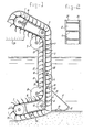
- the apparatus shown in Fig. 1 comprises a frame not shown in detail in which are supported the upper reversing wheel 1, the lower reversing wheel 2, a conveyor belt 3 and a high number of blades 4 integral therewith, as well as in engagement with the inner surface of the belt an upper guiding wheel 5 and a lower guiding wheel 6 and upper and lower guiding wheels 7 and 8 respectively engaging the edges of the belt.
- the frame carries a tube 9 the front wall 10 of which carries with its lower end at 11 a supporting construction with guiding shoe 12, said guiding shoe may be provided with fluidizing devices such as jet nozzles 13.
- the lower part 14 of the frame bearing the lower reversing wheel 2 may if desired by pivotable around the axis of the guiding wheel 6, i.e. around the axis 15, in order to give it another angle of inclination with respect to the tube 9 by means of a hydraulic cylinder not shown.
- the upper reversing wheel 1 is guided in the frame and biased by a biasing device 16 indicated only schematically.
- This may be a hydraulic cylinder or a spring which may be put under tension.
- the frame supports a second tube 17 for the returning section 18 of the belt 3, said tube 17 having an inlet mouth 19 above the water and near its lower end 20 positioned right above the guiding wheel 8, is provided with a pressurized air supply 21.
- the frame may have side plates 23 indicated with dashed lines and positioned at both sides of the belt and of which the lower edge 24 may be positioned slightly lower than the extreme edges of the blades, at the same level or slightly higher.
- Fig. 2 shows that between the blades 4, side walls 25 and 26 integral with blades and belt may be provided, which either may consist of elastically extensible material as indicated by 25, or as indicated by 26 may consist of foldable material. Their extreme edges may be spaced slightly from the extreme edge 28 of the blade as shown in Fig. 1 with 27. In this way backet-shaped blades are created spreading at the upper reverse wheel 1 in order to stimulate the dumping into the chute 29 and confining at the lower guiding wheel 6.
- the frame is shown in a position in which the tubes stand vertical.
- each angular adjustment with respect to the vertical as usual in the bucket ladder is also possible resulting by combination with the adjustable lower portion 14 in an optimal benefit of the digging properties of the belt.
- the device according to the invention may operate with relatively small blades moving with a high velocity by which a remarkably higher feeding up capacity may be obtained.
- the flexible rubber blades integral with the belt or fixed stationary thereon may be compliant when the blades encounter non-displaceable material such as too big stone pieces.
- the returning section 18 moving through the tube 17 applies a propelling action downwards.
- the inlet of said tube is positioned above the water level so that only near the lower end 20 water can enter.
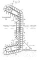
- Fig. 3 differs from that shown. in Fig. 1 in that the tube 9 terminates at its upper end above the reversing wheel 1.
- the biasing device comprises a hydraulic cylinder 30 in stead of a spring 16 and the tubes 9 and 17 are implemented telescopically such that the lower part 9a and 17a may be shifted within the upper part 9b and 17b.
- the working depth of the lower portion 14 is controllable.
Landscapes
- Engineering & Computer Science (AREA)
- Mechanical Engineering (AREA)
- Mining & Mineral Resources (AREA)
- Civil Engineering (AREA)
- General Engineering & Computer Science (AREA)
- Structural Engineering (AREA)
- Ship Loading And Unloading (AREA)
- Medicines Containing Plant Substances (AREA)
- Pharmaceuticals Containing Other Organic And Inorganic Compounds (AREA)
- Electronic Switches (AREA)
- Structure Of Belt Conveyors (AREA)
Claims (10)
Applications Claiming Priority (2)
| Application Number | Priority Date | Filing Date | Title |
|---|---|---|---|
| NL8105010A NL8105010A (nl) | 1981-11-05 | 1981-11-05 | Baggerinrichting. |
| NL8105010 | 1981-11-05 |
Publications (2)
| Publication Number | Publication Date |
|---|---|
| EP0079103A1 EP0079103A1 (de) | 1983-05-18 |
| EP0079103B1 true EP0079103B1 (de) | 1985-08-14 |
Family
ID=19838322
Family Applications (1)
| Application Number | Title | Priority Date | Filing Date |
|---|---|---|---|
| EP82201379A Expired EP0079103B1 (de) | 1981-11-05 | 1982-11-03 | Baggervorrichtung |
Country Status (5)
| Country | Link |
|---|---|
| US (1) | US4430812A (de) |
| EP (1) | EP0079103B1 (de) |
| JP (1) | JPS5883733A (de) |
| DE (1) | DE3265451D1 (de) |
| NL (1) | NL8105010A (de) |
Families Citing this family (14)
| Publication number | Priority date | Publication date | Assignee | Title |
|---|---|---|---|---|
| GB2163791B (en) * | 1984-04-03 | 1988-06-22 | Abdul Karim Al Rabia A Jawad S | Electro-mechanical excavators |
| DE4015126C1 (de) * | 1990-05-11 | 1991-10-24 | Man Gutehoffnungshuette Ag, 4200 Oberhausen, De | |
| NL9402208A (nl) * | 1994-12-23 | 1996-08-01 | Johannes Petrus De Koning | Baggermolen en werkwijze voor het baggeren. |
| DE29811653U1 (de) | 1998-06-12 | 1998-09-17 | Josef Möbius Bau-Gesellschaft (GmbH & Co.), 22549 Hamburg | Vorrichtung zur Aufnahme oder Ablage von Sedimenten von oder auf einem Gewässerboden |
| US6467200B1 (en) * | 2000-03-20 | 2002-10-22 | Caterpillar Inc. | Shoe mechanism for an excavating wheel and associated method |
| WO2006138617A2 (en) * | 2005-06-17 | 2006-12-28 | Platt Michael D | Top loading wedge with adjustably engageable bottom apparatus and method |
| GB2452273A (en) * | 2007-08-29 | 2009-03-04 | Haigh Eng Co Ltd | Band screen |
| GB0722387D0 (en) * | 2007-11-14 | 2007-12-27 | Haigh Engineering Company The | Grift separator |
| FR2924699B1 (fr) * | 2007-12-11 | 2010-04-23 | Total France | Dispositif pour le transport de particules, installation et procede pour le chargement d'une enceinte avec le dispositif |
| NL2004998C2 (nl) * | 2010-06-29 | 2011-12-30 | Nicolaas Gerardus Konijn | Inrichting voor het uitbaggeren van waterbodems zoals in plassen, meren, rivieren, enz. |
| US9708791B2 (en) * | 2014-10-16 | 2017-07-18 | Andrew Strutynsky | Apparatus, systems and methods for excavating trenches in earth or soil and installing underground conduits or other media |
| CN107879404B (zh) * | 2017-12-24 | 2024-09-27 | 洛阳明创矿山冶金设备有限公司 | 一种水处理池内污泥清理设备 |
| EP4321455A4 (de) * | 2021-06-09 | 2024-10-09 | Shanghai Yamato Scale Co., Ltd | Zugmechanismus einer rohrleitungsfördervorrichtung und rohrleitungsfördervorrichtung |
| CN119531437B (zh) * | 2025-01-17 | 2025-05-13 | 山西省邮电建设工程有限公司 | 一种便携式的浅基坑开挖装置 |
Family Cites Families (14)
| Publication number | Priority date | Publication date | Assignee | Title |
|---|---|---|---|---|
| US285565A (en) * | 1883-09-25 | brotherhood | ||
| US227988A (en) * | 1880-05-25 | Apparatus for dredging and separating gold | ||
| US816958A (en) * | 1905-08-09 | 1906-04-03 | Pierre Bouery | Dredger and bed-rock cleaner. |
| GB552121A (en) * | 1941-09-18 | 1943-03-24 | Cecil Wheatley Stancliffe | Improvements relating to digging machines |
| US2620575A (en) * | 1947-06-27 | 1952-12-09 | Lorin L Cronkright | Loading conveyer |
| US3146537A (en) * | 1962-05-07 | 1964-09-01 | Ellicott Machine Corp | Floating dredge design |
| US3160966A (en) * | 1962-06-20 | 1964-12-15 | James C Skakel | Submerged dredging device with air filled hood |
| DK112160B (da) * | 1963-07-12 | 1968-11-11 | H Weyers | Maskine til gravning af grøfter. |
| NL6812058A (de) * | 1968-08-23 | 1970-02-25 | ||
| BE755650A (fr) * | 1969-09-06 | 1971-02-15 | Braun Franz | Dispositif mobile de curage |
| US3762558A (en) * | 1971-09-30 | 1973-10-02 | J Anderson | Anti-pollution barge and conveyer assembly |
| FR2195563B2 (de) * | 1972-08-09 | 1977-09-02 | Puretic Juraj | |
| US3874101A (en) * | 1974-01-31 | 1975-04-01 | Oliver Frank Cummins | Dredger with adjustable endless digger and rotary mud slinger |
| US3968579A (en) * | 1975-02-24 | 1976-07-13 | Rossfelder Andre M | Apparatus for sediment dredging and ocean mineral gathering |
-
1981
- 1981-11-05 NL NL8105010A patent/NL8105010A/nl not_active Application Discontinuation
-
1982
- 1982-09-28 US US06/426,183 patent/US4430812A/en not_active Expired - Fee Related
- 1982-11-03 DE DE8282201379T patent/DE3265451D1/de not_active Expired
- 1982-11-03 EP EP82201379A patent/EP0079103B1/de not_active Expired
- 1982-11-05 JP JP57193549A patent/JPS5883733A/ja active Pending
Also Published As
| Publication number | Publication date |
|---|---|
| DE3265451D1 (en) | 1985-09-19 |
| US4430812A (en) | 1984-02-14 |
| NL8105010A (nl) | 1983-06-01 |
| JPS5883733A (ja) | 1983-05-19 |
| EP0079103A1 (de) | 1983-05-18 |
Similar Documents
| Publication | Publication Date | Title |
|---|---|---|
| US4430812A (en) | Endless belt dredger | |
| US9222238B2 (en) | Drag head and trailing suction hopper dredger | |
| US3248812A (en) | Collector and hoist for aggregates | |
| US4854058A (en) | Dredging apparatus having a diver-operated hand-held dredge head for quasi-closed loop system | |
| US4418484A (en) | Method of dredging and dredging implement | |
| CN112726716A (zh) | 一种平原河道河底淤泥清理装置及其清理方法 | |
| CN1095439A (zh) | 吸取道床道碴用的机械 | |
| US5259699A (en) | Pipeline padding system | |
| US20160244926A1 (en) | Method and device for deepening riverbeds and their cleaning from sediments | |
| US4714378A (en) | Apparatus and method for trenching subsea pipelines | |
| US7395618B2 (en) | Subsea excavation and suction device | |
| US20050268499A1 (en) | Method and apparatus for pumping with a dredge | |
| US5638620A (en) | Dredging vessel, dredging assembly and method of dredging | |
| US5540003A (en) | Padding machine with shaker for separator | |
| US4585274A (en) | Mineral and metal particle recovery apparatus and method | |
| JPH09144057A (ja) | 水路浚渫方法 | |
| EP0259472B1 (de) | Bagger | |
| US3874101A (en) | Dredger with adjustable endless digger and rotary mud slinger | |
| RU2107776C1 (ru) | Способ выполнения подводных земляных работ с использованием дноуглубительного земснаряда и гидромониторное устройство для разработки траншей под водой, гидромониторный трубозаглубитель-траншеекопатель (варианты), трубозаглубитель-траншеекопатель (варианты) | |
| US3761132A (en) | Apparatus and method for repositioning earthen material | |
| US2787844A (en) | Ditch cleaning implement | |
| WO1993000789A1 (en) | Ditch excavator | |
| US4319414A (en) | Dredgehead having forward water-deflecting means comprising two transverse elements | |
| EA006954B1 (ru) | Устройство формирования и подготовки траншеи | |
| CA1259635A (en) | Diluvial diving dredge |
Legal Events
| Date | Code | Title | Description |
|---|---|---|---|
| PUAI | Public reference made under article 153(3) epc to a published international application that has entered the european phase |
Free format text: ORIGINAL CODE: 0009012 |
|
| AK | Designated contracting states |
Designated state(s): BE DE FR GB NL |
|
| 17P | Request for examination filed |
Effective date: 19831020 |
|
| GRAA | (expected) grant |
Free format text: ORIGINAL CODE: 0009210 |
|
| AK | Designated contracting states |
Designated state(s): BE DE FR GB NL |
|
| REF | Corresponds to: |
Ref document number: 3265451 Country of ref document: DE Date of ref document: 19850919 |
|
| ET | Fr: translation filed | ||
| PLBE | No opposition filed within time limit |
Free format text: ORIGINAL CODE: 0009261 |
|
| STAA | Information on the status of an ep patent application or granted ep patent |
Free format text: STATUS: NO OPPOSITION FILED WITHIN TIME LIMIT |
|
| 26N | No opposition filed | ||
| PGFP | Annual fee paid to national office [announced via postgrant information from national office to epo] |
Ref country code: NL Payment date: 19871130 Year of fee payment: 6 |
|
| PG25 | Lapsed in a contracting state [announced via postgrant information from national office to epo] |
Ref country code: GB Effective date: 19881103 |
|
| PG25 | Lapsed in a contracting state [announced via postgrant information from national office to epo] |
Ref country code: BE Effective date: 19881130 |
|
| BERE | Be: lapsed |
Owner name: IHC HOLLAND N.V. Effective date: 19881130 |
|
| PG25 | Lapsed in a contracting state [announced via postgrant information from national office to epo] |
Ref country code: NL Effective date: 19890601 |
|
| NLV4 | Nl: lapsed or anulled due to non-payment of the annual fee | ||
| GBPC | Gb: european patent ceased through non-payment of renewal fee | ||
| PG25 | Lapsed in a contracting state [announced via postgrant information from national office to epo] |
Ref country code: FR Free format text: LAPSE BECAUSE OF NON-PAYMENT OF DUE FEES Effective date: 19890731 |
|
| PG25 | Lapsed in a contracting state [announced via postgrant information from national office to epo] |
Ref country code: DE Effective date: 19890801 |
|
| REG | Reference to a national code |
Ref country code: FR Ref legal event code: ST |