EP0079010A1 - Smoke detector - Google Patents
Smoke detector Download PDFInfo
- Publication number
- EP0079010A1 EP0079010A1 EP82110013A EP82110013A EP0079010A1 EP 0079010 A1 EP0079010 A1 EP 0079010A1 EP 82110013 A EP82110013 A EP 82110013A EP 82110013 A EP82110013 A EP 82110013A EP 0079010 A1 EP0079010 A1 EP 0079010A1
- Authority
- EP
- European Patent Office
- Prior art keywords
- smoke detector
- radiation
- detector according
- pulse
- radiation source
- Prior art date
- Legal status (The legal status is an assumption and is not a legal conclusion. Google has not performed a legal analysis and makes no representation as to the accuracy of the status listed.)
- Granted
Links
- 239000000779 smoke Substances 0.000 title claims abstract description 43
- 230000005855 radiation Effects 0.000 claims abstract description 68
- 238000011156 evaluation Methods 0.000 claims abstract description 3
- 239000003990 capacitor Substances 0.000 claims description 14
- 230000000903 blocking effect Effects 0.000 claims description 8
- 230000001960 triggered effect Effects 0.000 claims description 4
- 230000005669 field effect Effects 0.000 claims description 3
- 238000001514 detection method Methods 0.000 claims 1
- 238000011109 contamination Methods 0.000 abstract description 8
- 230000001419 dependent effect Effects 0.000 abstract description 2
- 230000032683 aging Effects 0.000 description 3
- 238000012544 monitoring process Methods 0.000 description 3
- 230000035945 sensitivity Effects 0.000 description 3
- 230000008878 coupling Effects 0.000 description 2
- 238000010168 coupling process Methods 0.000 description 2
- 238000005859 coupling reaction Methods 0.000 description 2
- 230000009699 differential effect Effects 0.000 description 2
- 239000000428 dust Substances 0.000 description 2
- 230000001771 impaired effect Effects 0.000 description 2
- 230000001105 regulatory effect Effects 0.000 description 2
- 206010069201 Smoke sensitivity Diseases 0.000 description 1
- 230000003321 amplification Effects 0.000 description 1
- 230000005494 condensation Effects 0.000 description 1
- 238000009833 condensation Methods 0.000 description 1
- 230000002431 foraging effect Effects 0.000 description 1
- 239000007789 gas Substances 0.000 description 1
- 230000010354 integration Effects 0.000 description 1
- 230000007257 malfunction Effects 0.000 description 1
- 238000003199 nucleic acid amplification method Methods 0.000 description 1
Images
Classifications
-
- G—PHYSICS
- G08—SIGNALLING
- G08B—SIGNALLING OR CALLING SYSTEMS; ORDER TELEGRAPHS; ALARM SYSTEMS
- G08B29/00—Checking or monitoring of signalling or alarm systems; Prevention or correction of operating errors, e.g. preventing unauthorised operation
- G08B29/02—Monitoring continuously signalling or alarm systems
- G08B29/04—Monitoring of the detection circuits
- G08B29/043—Monitoring of the detection circuits of fire detection circuits
-
- G—PHYSICS
- G08—SIGNALLING
- G08B—SIGNALLING OR CALLING SYSTEMS; ORDER TELEGRAPHS; ALARM SYSTEMS
- G08B17/00—Fire alarms; Alarms responsive to explosion
- G08B17/10—Actuation by presence of smoke or gases, e.g. automatic alarm devices for analysing flowing fluid materials by the use of optical means
- G08B17/103—Actuation by presence of smoke or gases, e.g. automatic alarm devices for analysing flowing fluid materials by the use of optical means using a light emitting and receiving device
- G08B17/107—Actuation by presence of smoke or gases, e.g. automatic alarm devices for analysing flowing fluid materials by the use of optical means using a light emitting and receiving device for detecting light-scattering due to smoke
-
- G—PHYSICS
- G08—SIGNALLING
- G08B—SIGNALLING OR CALLING SYSTEMS; ORDER TELEGRAPHS; ALARM SYSTEMS
- G08B17/00—Fire alarms; Alarms responsive to explosion
- G08B17/10—Actuation by presence of smoke or gases, e.g. automatic alarm devices for analysing flowing fluid materials by the use of optical means
- G08B17/11—Actuation by presence of smoke or gases, e.g. automatic alarm devices for analysing flowing fluid materials by the use of optical means using an ionisation chamber for detecting smoke or gas
- G08B17/113—Constructional details
-
- G—PHYSICS
- G08—SIGNALLING
- G08B—SIGNALLING OR CALLING SYSTEMS; ORDER TELEGRAPHS; ALARM SYSTEMS
- G08B29/00—Checking or monitoring of signalling or alarm systems; Prevention or correction of operating errors, e.g. preventing unauthorised operation
- G08B29/18—Prevention or correction of operating errors
- G08B29/20—Calibration, including self-calibrating arrangements
- G08B29/24—Self-calibration, e.g. compensating for environmental drift or ageing of components
Definitions
- the invention relates to a smoke detector with a radiation source operated in pulses, a radiation receiver arranged outside the direct radiation area of the radiation source, which is exposed to scattered radiation in the presence of smoke in the radiation area and emits output signals, and an evaluation circuit which has switching elements which, when the output signals exceed a predetermined threshold value forward a signal to a flip-flop for emitting an alarm signal.
- Such a smoke detector is known for example from WO-PA 80/1326 and EP-PA 14 779.
- a radiation source is controlled by a pulse generator and emits short-lasting radiation pulses.
- the receiver picks up the radiation that is scattered by smoke in the scattering volume, but also radiation that is reflected by the walls.
- To compensate for aging and the temperature response of the transmitter and receiver e.g. in US Pat. No. 4,180,742
- a radiation source positioned at the bottom emits light in a conical shape upwards.
- the main radiation receiver is positioned centrally symmetrically at the top, the reference receiver somewhat above at the side in the direct radiation path of the transmitter. With this type of positioning, dust is only deposited on the radiation source. Condensation from gases, on the other hand, will equally prove the main recipient and reference recipient.
- the regulation of the light output of the transmitter by measuring the signal of the reference cell therefore results in a scatter signal generated by the smoke on the main receiving cell, which is independent of the contamination of the detector.
- the electronic circuit essentially consists of an oscillator for the power supply to the radiation source regulated by the reference cell, an amplifier and a threshold value detector with differential properties. If the reception pulse changes very slowly, as can be generated by contamination, the threshold value is shifted with the height of the reception pulse. When the reception pulse increases rapidly, as is produced by smoke generated by fire, the threshold value changes only insignificantly, and the flip-flop is triggered when a certain reception height is reached. The threshold value detector with differential properties is thus able to correct the slow changes in the received pulse. The combination of this threshold value detector with the radiation pulse controlled by the reference cell results in a smoke detector which does not change its sensitivity to smoke even when heavily soiled. In addition, the aging of the radiation source and the temperature dependence are corrected.
- the regulation of the radiation source can also be used as follows to trigger an interference signal:
- the smoke detector retains an unchanged sensitivity to smoke. As soon as this circuit reaches the limits of the control possibility, this can be detected and an interference signal can be triggered.
- Such a detector thus triggers an interference signal as long as it still has hardly any change in smoke sensitivity, but would soon become insensitive to further contamination or aging of the radiation source.
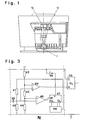
- Fig. 1 the structure of a smoke detector according to the invention is shown in section.
- the radiation source 1 emits radiation in the shape of a hollow cone into the enclosed space of the detector.
- a central aperture (50) keeps direct radiation away from the radiation receiver 16.
- the reference cell 12 is positioned in the radiation cone. This arrangement ensures that radiation receiver 16 and reference cell 12 become equally dirty. In particular, dust is mainly deposited on the radiation source 1 and thus influences the reference and scattered light signals equally.
- a radiation transmitter S In the circuit of an embodiment of the smoke detector according to the invention shown in FIG. 2, a radiation transmitter S, a radiation detector A, a correlator C, a threshold detector N, an integrator I, an alarm flip-flop K and lie between two lines L 1 and L 2 carrying direct voltage a monitoring circuit with flip-flop U.
- the radiation transmitter S consists of an oscillator which conducts a current of approximately one ampere approximately 100 ps through the radiation source 1 at a time interval of approximately two seconds.
- the radiation source 1 consists of a light or IR radiation emitting diode.
- the oscillator consists of the power transistor 2 with associated limiting resistor 3, from the drive circuit consisting of transistor 4 with associated limiting resistor 5, and from the feedback element consisting of resistor 7 and capacitor 6.
- the large capacitor 10 supplies the current pulse for the radiation source 1; it is charged via resistor 11.
- the current pulse is triggered when the resistors 8 and 9 at the base of the transistor 4 supply the voltage which makes it conductive.
- the current through the light-emitting diode is regulated via the reference cell (phototransistor 12) with measuring resistor 13 and feedback resistor 14. As soon as the voltage across the resistor 13 is high enough, the transistor 15 becomes somewhat conductive and thus reduces the base current of the power transistor 2.
- a photo cell can also be used instead of a photo transistor.
- the radiation detector A consists of the radiation receiver 16 designed as a photocell and the two-stage amplifier consisting of the transistors 17 and 18, the collector resistors 22 and 23, the emitter resistor 20 with parallel capacitor 21 for higher pulse amplification and the feedback resistor 19. Via resistor 24 and capacitor 25 the blocking pulse is generated from the oscillator. On K lecturer ol of transistor 18, a negative blocking pulse, for which purpose this counted in a positive direction of the amplified received pulse appears across the coupling capacitor 26 thereby.
- a phototransistor can also be used as the radiation receiver 16: this would simultaneously replace the transistor 17.
- a self-conducting P-channel junction field-effect transistor 27 is used as the correlator C, the gate of which is normally low, which makes it conductive and thus any possible interference pulse is short-circuited.
- the gate is high only during the pulse and the JFET 27 blocks and thus allows the receive and block pulse to pass.
- the threshold detector N consists of the self-conducting N-channel junction field-effect transistor 28 and the holding stage with capacitor 29 and the high-resistance resistor 30.
- the FET 28 With each pulse, the FET 28 is made conductive by the negative blocking pulse. This generates a reset pulse via transistor 31 with base resistor 32.
- the capacitor 29 is charged via the forward diode gate-source of the FET 28. As long as the pulse height remains unchanged, the capacitor 29 remains essentially at the same potential. It discharges very little via resistor 30 and is recharged to the previous potential at the next pulse. If the pulse height changes very slowly, the potential of the capacitor 29 follows accordingly. If smoke penetrates the detector, the pulse at the gate of the FET 28 becomes smaller in amount. If it becomes small enough, the F ET will no longer conduct during the pulse, as a result of which no reset pulse will be generated.
- the integration stage I consists of a counter 33 (eg 4024), which receives counting pulses from the oscillator with each radiation pulse. As long as reset pulses are generated, it is also reset to 0 for each pulse. If there are no reset pulses, the output Q n goes high after 2 pulses.
- a counter 33 eg 4024
- the flip-flop K consists of the thyristor 34, which is driven by the output Q of the counter.
- the Zener diode 35 generates a voltage (eg 6 V) in order to distinguish the alarm condition from the fault condition.
- the monitoring circuit U consists of the voltage divider with resistors 37 and 38 and the thyristor 36.
- the resistor 3 measures the current through the radiation source 1. As soon as this becomes too high as a result of contamination or aging of the radiation source 1, the thyristor 36 is activated and a malfunction is thus indicated .
- the circuit shown is only an example. Parts can also be omitted, e.g. Monitoring circuit U or the correlator C.
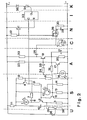
- the various elements can also be designed differently, e.g. the threshold value detector can also be differentiated digitally using a counter and a digital / analog converter, as is shown in FIG. 3.
- the pulse signal is added to the voltage at the voltage divider formed from the resistors 40 and 41 and fed to the negative input of the comparators 45 and 46. These receive voltages on their positive input, which are generated by resistors 42, 43 and 44.
- the count pulse which is inverted with the element 49, generates a state of the counter 47 which is 1 higher or lower (for example 14516).
- the state of the counter 47 generates the DC input voltage via the resistors 41 and 40 via the parallel digital / analog converter 48. This circuit ensures that in the idle state the pulse voltage at the negative input oscillates just around the voltage at the positive input of the comparator 46.
Landscapes
- Physics & Mathematics (AREA)
- General Physics & Mathematics (AREA)
- Business, Economics & Management (AREA)
- Computer Security & Cryptography (AREA)
- Chemical & Material Sciences (AREA)
- Analytical Chemistry (AREA)
- Engineering & Computer Science (AREA)
- Emergency Management (AREA)
- Fire-Detection Mechanisms (AREA)
- Investigating Or Analysing Materials By Optical Means (AREA)
- Control Of Motors That Do Not Use Commutators (AREA)
- Vehicle Body Suspensions (AREA)
- Gyroscopes (AREA)
Abstract
Bei einem Rauchdetektor mit einer impulsweise betriebenen Strahlungsquelle (1) ist ausserhalb des direkten Strahlungsbereichs der Strahlungsquelle (1) ein Strahlungsempfänger (16) angeordnet, welcher bei Anwesenheit von Rauch im Strahlungsbereich durch Streustrahlung beaufschlagt wird und Ausgangsimpulse an eine Auswerteschaltung abgibt, welche Schaltelemente (A, N) aufweist, welche bei Ueberschreiten der Ausgangsimpulse über einen vorgegebenen Schwellenwert ein Alarmsignal weiterleiten. Nahe bei dem Strahlungsemfänger (16) ist im direkten Strahlengang der Strahlungsquelle (1) eine Referenzzelle (12) angeordnet, welche die Ausstrahlung der Strahlungsquelle (1) steuert. Ferner sind weitere Mittel (28, 29, 30) vorhanden, welche bei langsamer Aenderung des Empfangsimpulses den Schwellenwert mit einer Zeitkonstante von mehr als einer Minute nachführen. Dadurch ergibt sich ein von der Rauchdichte abhängiges Ausgangssignal des Strahlungsempfängers (16), welches unabhängig von der Verschmutzung des Melders ist.In a smoke detector with a pulsed radiation source (1), a radiation receiver (16) is arranged outside the direct radiation area of the radiation source (1), which is acted upon by scattered radiation in the presence of smoke in the radiation area and outputs output pulses to an evaluation circuit, which switching elements (A , N), which forwards an alarm signal when the output pulses exceed a predetermined threshold value. A reference cell (12), which controls the radiation of the radiation source (1), is arranged close to the radiation receiver (16) in the direct beam path of the radiation source (1). Furthermore, there are further means (28, 29, 30) which track the threshold value with a time constant of more than one minute when the received pulse changes slowly. This results in an output signal of the radiation receiver (16) which is dependent on the smoke density and which is independent of the contamination of the detector.
Description
Die Erfindung betrifft einen Rauchdetektor mit einer impulsweise betriebenen Strahlungsquelle, einem ausserhalb des direkten Strahlungsbereichs der Strahlungsquelle angeordneten, bei Anwesenheit von Rauch im Strahlungsbereich durch Streustrahlung beaufschlagten und Ausgangssignale abgebenden Strahlungsempfänger und einer Auswerteschaltung, welche Schaltelemente aufweist, die bei Ueberschreiten der Ausgangssignale über einen vorgegebenen Schwellenwert ein Signal an eine Kippstufe zur Abgabe eines Alarmsignals weiterleiten.The invention relates to a smoke detector with a radiation source operated in pulses, a radiation receiver arranged outside the direct radiation area of the radiation source, which is exposed to scattered radiation in the presence of smoke in the radiation area and emits output signals, and an evaluation circuit which has switching elements which, when the output signals exceed a predetermined threshold value forward a signal to a flip-flop for emitting an alarm signal.
Ein derartiger Rauchdetektor ist beispielsweise aus der WO-PA 80/1326 und der EP-PA 14 779 bekannt. Dabei wird eine Strahlungsquelle von einem Impulsgeber angesteuert und sendet kurzdauernde Strahlungsimpulse aus. Der Empfänger nimmt die Strahlung auf, welche von Rauch im Streuvolumen gestreut, aber auch solche, die von den Wänden reflektiert wird. Zur Kompensation von Alterung und Temperaturgang vom Sender und Empfänger ist (z.B. in US-PS 4'180'742) bereits vorgeschlagen worden, bei einem mit Gleichlicht betriebenen Streulichtmelder mit einer zweiten, identischen Empfangszelle das ausgesandte Licht des Senders zu messen und zu regeln. Dies genügt aber nicht zur Kompensation aller möglichen Veränderungen durch Verschmutzung.Such a smoke detector is known for example from WO-PA 80/1326 and EP-PA 14 779. A radiation source is controlled by a pulse generator and emits short-lasting radiation pulses. The receiver picks up the radiation that is scattered by smoke in the scattering volume, but also radiation that is reflected by the walls. To compensate for aging and the temperature response of the transmitter and receiver (e.g. in US Pat. No. 4,180,742), it has already been proposed to measure and regulate the emitted light of the transmitter in the case of a scattered light detector operated with constant light with a second, identical receiving cell. However, this is not sufficient to compensate for all possible changes due to contamination.
Der Erfindung liegt die Aufgabe zu Grunde, einen-Rauchdetektor zu schaffen, dessen Funktionsfähigkeit durch keine Art von Verschmutzung beeinträchtigt wird und dessen Rauchempfindlichkeit über längere Zeiträume stabil bleibt. Eine weitere Aufgabe der Erfindung besteht darin, einen Rauchdetektor zu schaffen, der ein Störsignal abgibt, wenn seine Verschmutzung so weit fortgeschritten ist, dass seine Funktionsfähigkeit beeinträchtigt werden könnte.The invention is based on the object of providing a smoke detector whose functionality is not impaired by any type of contamination and whose sensitivity to smoke remains stable over long periods of time. Another object of the invention is to provide a smoke detector which emits an interference signal when its contamination has progressed to such an extent that its functionality could be impaired.
Diese Aufgabe wird erfindungsgemäss durch die im kennzeichnenden Teil des Patentanspruches 1 definierten Merkmale gelöst. Bevorzugte Ausführungsformen und weitere Ausgestaltungen der Erfindung sind in den abhängigen Ansprüchen definiert.According to the invention, this object is achieved by the features defined in the characterizing part of patent claim 1. Preferred embodiments and further refinements of the invention are defined in the dependent claims.
Gemäss einer Ausgestaltung des erfindungsgemässen Rauchdetektors sendet eine unten positionierte Strahlungsquelle kegelförmig nach oben Licht aus. Der Hauptstrahlungsempfänger ist zentralsymetrisch oben positioniert, der Referenzempfänger etwas seitlich oben im direkten Strahlungsgang des Senders. Bei dieser Art der Positionierung wird Staub nur auf der Strahlungsquelle abgelagert. Kondensation aus Gasen hingegen wird gleichmässig Hauptempfänger und Referenzempfänger belegen. Die Regelung der Lichtleistung des Senders durch die Messung des Signals der Referenzzelle ergibt deshalb ein vom Rauch erzeugtes Streusignal auf der Hauptempfangszelle, welches unabhängig von der Verschmutzung des Melders ist.According to an embodiment of the smoke detector according to the invention, a radiation source positioned at the bottom emits light in a conical shape upwards. The main radiation receiver is positioned centrally symmetrically at the top, the reference receiver somewhat above at the side in the direct radiation path of the transmitter. With this type of positioning, dust is only deposited on the radiation source. Condensation from gases, on the other hand, will equally prove the main recipient and reference recipient. The regulation of the light output of the transmitter by measuring the signal of the reference cell therefore results in a scatter signal generated by the smoke on the main receiving cell, which is independent of the contamination of the detector.
Die elektronische Schaltung gemäss einer weiteren Ausgestaltung besteht im wesentlichen aus einem Oszillator zur durch die Referenzzelle geregelten Stromversorgung der Strahlungsquelle, einem Verstärker und einem Schwellenwertdetektor mit Differentialeigenschaften. Bei sehr langsamer Veränderung des Empfangspulses, wie sie durch Verschmutzung erzeugt werden kann, wird der Schwellenwert mit der Höhe des Empfangspulses verschoben. Bei schneller Erhöhung des Empfangspulses, wie es durch Feuer entstandener Rauch erzeugt, verändert sich der Schwellenwert nur unwesentlich, und bei Erreichen einer bestimmten Empfangshöhe wird die Kippstufe ausgelöst. Der Schwellenwertdetektor mit Differentialeigenschaften vermag somit die langsamen Aenderungen des Empfangspulses zu korrigieren. Die Kombination dieses Schwellenwertdetektors mit dem durch die Referenzzelle gesteuerten Strahlungspuls ergibt einen Rauchdetektor, der seine Rauchempfindlichkeit auch bei stärkerer Verschmutzung nicht verändert. Ausserdem werden die Alterung der Strahlungsquelle und die Temperaturabhängigkeit korrigiert.The electronic circuit according to a further embodiment essentially consists of an oscillator for the power supply to the radiation source regulated by the reference cell, an amplifier and a threshold value detector with differential properties. If the reception pulse changes very slowly, as can be generated by contamination, the threshold value is shifted with the height of the reception pulse. When the reception pulse increases rapidly, as is produced by smoke generated by fire, the threshold value changes only insignificantly, and the flip-flop is triggered when a certain reception height is reached. The threshold value detector with differential properties is thus able to correct the slow changes in the received pulse. The combination of this threshold value detector with the radiation pulse controlled by the reference cell results in a smoke detector which does not change its sensitivity to smoke even when heavily soiled. In addition, the aging of the radiation source and the temperature dependence are corrected.
Es hat sich als vorteilhaft erwiesen, in der vorerwähnten Schaltung Mittel vorzusehen, durch welche ein Sperrpuls erzeugt wird (beispielsweise durch einen elektrischen Puls eines Oszillators), sowie Mittel durch welche die Differenz dieses Sperrpulses und des Ausgangsimpulses des Strahlungsempfängers gebildet wird, welche dann als Rückstellsignal einer Zähleinrichtung zugeführt wird, wobei die Zähleinrichtung bei Ausbleiben des Rückstellsignals weitergeschaltet wird und bei Erreichen eines vorbestimmten Zählerstandes ein Alarmsignal auslöst. Eine derart verbesserte Schaltung ist besonders unempfinlich gegen elektrische Störungen, insbesondere hochfrequente elektrische Störungen, da diese höchstens ein zusätzliches Rückstellsignal für die Zähleinrichtung erzeugen können, wodurch der Rauchdetektor gegen die Auslösung von Fehlalarmen sicherer wird.It has proven to be advantageous to provide means in the aforementioned circuit by means of which a blocking pulse is generated (for example by an electrical pulse from an oscillator), and means by which the difference between this blocking pulse and the output pulse of the radiation receiver is formed, which is then used as a reset signal is fed to a counting device, the counting device being switched on if the reset signal is absent and triggering an alarm signal when a predetermined counter reading is reached. Such an improved circuit is particularly insensitive to electrical disturbances, in particular high-frequency electrical disturbances, since these can at most generate an additional reset signal for the counting device, as a result of which the smoke detector is safer against the triggering of false alarms.
Ausserdem kann die Regelung der Strahlungsquelle auch folgendermassen zur Auslösung eines Störsignals verwendet werden: Solange die Strahlungsquelle durch die Referenzzelle voll nachgeregelt werden kann, behält der Rauchdetektor eine unveränderte Rauchempfindlichkeit. Sobald dieser Schaltkreis an die Grenzen der Regelungsmöglichkeit kommt, kann dies detektiert werden, und ein Störsignal kann ausgelöst werden. Ein solcher Detektor löst also ein Störsignal aus, solange er zwar noch eine kaum veränderte Rauchempfindlichkeit besitzt, aber durch weitere Verschmutzung oder Alterung der Strahlungsquelle bald unempfindlich werden würde.In addition, the regulation of the radiation source can also be used as follows to trigger an interference signal: As long as the radiation source can be fully readjusted by the reference cell, the smoke detector retains an unchanged sensitivity to smoke. As soon as this circuit reaches the limits of the control possibility, this can be detected and an interference signal can be triggered. Such a detector thus triggers an interference signal as long as it still has hardly any change in smoke sensitivity, but would soon become insensitive to further contamination or aging of the radiation source.
Eine Ausführungsform des erfindungsgemässen Rauchdetektors wird im folgenden anhand der Figuren näher erläutert.An embodiment of the smoke detector according to the invention is explained in more detail below with reference to the figures.
- Fig. 1 zeigt einen Rauchdetektor mit Referenzzelle.Fig. 1 shows a smoke detector with a reference cell.
- Fig. 2 stellt die Schaltung eines bevorzugten Ausführungsbeispieles dar.Fig. 2 shows the circuit of a preferred embodiment.
- Fig. 3 stellt eine weitere Schaltung mit digitaler Nachführung dar. F ig. 3 shows a further circuit with digital tracking.
In Fig. 1 ist im Schnitt der Aufbau eines erfindungsgemässen Rauchdetektors dargestellt. Die Strahlungsquelle 1 sendet hohlkegelförmig Strahlung in den umschlossenen Raum des Detektors aus. Eine Zentralblende (50) hält direkte Strahlung vom Strahlungsempfänger 16 fern. Hingegen ist die Referenzzelle 12 im Strahlungskegel positioniert. Durch diese Anordnung wird erreicht, dass Strahlungsempfänger 16 und Referenzzelle 12 gleich stark verschmutzen. Insbesondere lagert sich Staub hauptsächlich auf der Strahlungsquelle 1 ab und beeinflusst damit Referenz- und Streulichtsignal gleichermassen.In Fig. 1, the structure of a smoke detector according to the invention is shown in section. The radiation source 1 emits radiation in the shape of a hollow cone into the enclosed space of the detector. A central aperture (50) keeps direct radiation away from the
Bei der in Fig. 2 dargestellten Schaltung einer Ausführungsform des erfindungsgemässen Rauchdetektors liegen zwischen zwei Gleichspannung führenden Leitungen Ll und L2 ein Strahlungssender S, ein Strahlungsaufnehmer A, ein Korrelator C, ein Schwellenwertdetektor N, ein Integrator I, eine Alarm-Kippstufe K und eine Ueberwachungsschaltung mit Kippstufe U.In the circuit of an embodiment of the smoke detector according to the invention shown in FIG. 2, a radiation transmitter S, a radiation detector A, a correlator C, a threshold detector N, an integrator I, an alarm flip-flop K and lie between two lines L 1 and L 2 carrying direct voltage a monitoring circuit with flip-flop U.
Der Strahlungssender S besteht aus einem Oszillator, der in einem Zeitabstand von etwa zwei Sekunden einen Strom von zirka einem Ampere etwa 100 ps durch die Strahlungsquelle 1 leitet. Die Strahlungsquelle 1 besteht aus einer Licht oder IR-Strahlung emittierenden Diode. Der Oszillator besteht aus dem Leistungstransistor 2 mit zugehörigem Begrenzungswiderstand 3, aus der aus Transistor 4 mit zugehörigem Begrenzungswiderstand 5 bestehenden Ansteuerschaltung, sowie aus dem aus Widerstand 7 und Kondensator 6 bestehenden Rückkopplungsglied. Der grosse Kondensator 10 liefert den Strompuls für die Strahlungsquelle 1; er wird über den Widerstand 11 aufgeladen.The radiation transmitter S consists of an oscillator which conducts a current of approximately one ampere approximately 100 ps through the radiation source 1 at a time interval of approximately two seconds. The radiation source 1 consists of a light or IR radiation emitting diode. The oscillator consists of the power transistor 2 with associated limiting
Der Strompuls wird ausgelöst, wenn die Widerstände 8 und 9 an der Basis des Transistors 4 die Spannung liefern, welche diesen leitend macht.The current pulse is triggered when the resistors 8 and 9 at the base of the transistor 4 supply the voltage which makes it conductive.
Der Strom durch die Leuchtdiode (Strahlungsquelle l) wird über die Referenzzelle (Fototransistor 12) mit Messwiderstand 13 und Rückkopplungswiderstand 14 geregelt. Sobald die Spannung am Widerstand 13 hoch genug ist, wird der Transistor 15 etwas leitend und reduziert damit den Basisstrom des Leistungstransistors 2. Statt eines Fototransistors kann natürlich auch eine Fotozelle verwendet werden.The current through the light-emitting diode (radiation source 1) is regulated via the reference cell (phototransistor 12) with measuring
Der Strahlungsaufnehmer A besteht aus dem als Fotozelle ausgebildeten Strahlungsempfänger 16 und dem zweistufigen Verstärker, bestehend aus den Transistoren 17 und 18, den Kollektorwiderständen 22 und 23, dem Emitterwiderstand 20 mit parallelem Kondensator 21 zur höheren Pulsverstärkung und dem Rückkopplungswiderstand 19. Ueber Widerstand 24 und Kondensator 25 wird aus dem Oszillator der Sperrpuls erzeugt. Am Kol- lektor von Transistor 18 erscheint über dem Kopplungskondensator 26 somit ein negativer Sperrpuls, wozu in positiver Richtung der verstärkte Empfangspuls dazugezählt wird. Statt einer Fotozelle kann als Strahlungsempfänger 16 auch ein Fototransistor verwendet werden: dieser würde gleichzeitig den Transistor 17 ersetzen.The radiation detector A consists of the
Als Korrelator C wird ein selbstleitender P-Kanal-Sperrschicht-Feldeffekttransistor 27 verwendet, dessen Gate normalerweise tief liegt, wodurch er leitend ist und damit jeder mögliche Störpuls kurzgeschlossen wird. Nur während des Pulses liegt das Gate hoch und der JFET 27 sperrt und lässt damit den Empfangs- und Sperrpuls durch.A self-conducting P-channel junction field-
Der Schwellwertdetektor N besteht aus dem selbstleitenden N-Kanal-Sperrschicht-Feldeffekttransistor 28 und der Haltestufe mit Kondensator 29 und dem hochohmigen Widerstand 30. Bei jedem Impuls wird durch den negativen Sperrpuls der FET 28 leitend gemacht. Dies erzeugt über Transistor 31 mit Basiswiderstand 32 einen Rückstellpuls. Gleichzeitig wird über die Vorwärtsdiode Gate-Source des FET 28 der Kondensator 29 aufgeladen. Solange die Pulshöhe unverändert bleibt, bleibt der Kondensator 29 im wesentlichen auf dem gleichen Potential. Ueber den Widerstand 30 entlädt er sich ganz wenig und wird beim nächsten Puls wieder auf das vorhergehende Potential aufgeladen. Bei sehr langsamen Aenderungen der Pulshöhe folgt das Potential des Kondensators 29 entsprechend. Falls Rauch in den Detektor eindringt, wird der Puls am Gate des FET 28 betragsmässig kleiner. Falls er klein genug wird, wird der FET während des Pulses nicht mehr leitend, wodurch kein Rückstellimpuls mehr erzeugt wird.The threshold detector N consists of the self-conducting N-channel junction field-
Die Integrationsstufe I besteht aus einem Zähler 33 (z.B. 4024), welcher Zählimpulse vom Oszillator bei jedem Strahlungsimpuls erhält. Solange Rückstellimpulse erzeugt werden, wird er aber bei jedem Puls auch wieder auf 0 zurückgestellt. Bei Ausbleiben der Rückstellimpulse geht nach 2 Pulsen der Ausgang Qn hoch.The integration stage I consists of a counter 33 (eg 4024), which receives counting pulses from the oscillator with each radiation pulse. As long as reset pulses are generated, it is also reset to 0 for each pulse. If there are no reset pulses, the output Q n goes high after 2 pulses.
Die Kippstufe K besteht aus dem Thyristor 34, der vom Ausgang Q des Zählers angesteuert wird. Die Zenerdiode 35 erzeugt eine Spannung (z.B. 6 V), um den Alarmzustand vom Störzustand zu unterscheiden.The flip-flop K consists of the
Die Ueberwachungsschaltung U besteht aus dem Spannungsteiler mit Widerständen 37 und 38 und dem Thyristor 36. Der Widerstand 3 misst den Strom durch die Strahlungsquelle 1. Sobald dieser infolge Verschmutzung oder Alterung der Strahlungsquelle 1 zu hoch wird, wird der Thyristor 36 angesteuert und damit Störung angezeigt.The monitoring circuit U consists of the voltage divider with
Die angegebene Schaltung ist nur ein Beispiel. Es lassen sich auch Teile weglassen, wie z.B. Ueberwachungschaltung U oder der Korrelator C. Die verschiedenen Elemente lassen sich auch anders ausbilden, z.B. kann die Differenzierung des Schwellenwertdetektors auch digital mit einem Zähler und einem Digital/Analog-Wandler erfolgen, wie dies in Fig. 3 dargestellt wird.The circuit shown is only an example. Parts can also be omitted, e.g. Monitoring circuit U or the correlator C. The various elements can also be designed differently, e.g. the threshold value detector can also be differentiated digitally using a counter and a digital / analog converter, as is shown in FIG. 3.
Ueber den Kopplungskondensator 39 wird das Pulssignal zu der Spannung an dem aus den Widerständen 40 und 41 gebildeten Spannungsteiler addiert und an den negativen Eingang der Komparatoren 45 und 46 geführt. Diese erhalten auf ihren positiven Eingang Spannungen, die durch die Widerstände 42, 43 und 44 erzeugt werden. Am Ende jedes Pulses erzeugt je nach dem Zustand des Komparators 46 der Zählimpuls, welcher mit dem Element 49 invertiert wird, einen um 1 höheren oder tieferen Zustand des Zählers 47 (z.B. 14516). Der Zustand des Zählers 47 erzeugt über den parallelen Digital/Analog-Wandler 48 die Eingangsgleichspannung über die Widerstände 41 und 40. Durch diese Schaltung wird erreicht, dass im Ruhezustand die Pulsspannung am negativen Eingang gerade um die Spannung am positiven Eingang des Komparators 46 pendelt. Bei schneller Verminderung des Betrages des Pulses kann der Zähler 47 diese Spannung nicht nachführen. Sobald der Puls die Spannung am positiven Eingang des Komparators 45 nicht mehr erreicht, wird kein Rückstellimpuls mehr erzeugt und der Zähler 33 wird nicht mehr rückgestellt. Diese Art von Schaltung lässt sich natürlich auch in einer Detektorschaltung ohne Sperrpuls verwenden.


Claims (14)
Priority Applications (1)
| Application Number | Priority Date | Filing Date | Title |
|---|---|---|---|
| AT82110013T ATE20398T1 (en) | 1981-11-11 | 1982-10-29 | SMOKE DETECTOR. |
Applications Claiming Priority (2)
| Application Number | Priority Date | Filing Date | Title |
|---|---|---|---|
| CH7248/81 | 1981-11-11 | ||
| CH724881A CH655396B (en) | 1981-11-11 | 1981-11-11 |
Publications (2)
| Publication Number | Publication Date |
|---|---|
| EP0079010A1 true EP0079010A1 (en) | 1983-05-18 |
| EP0079010B1 EP0079010B1 (en) | 1986-06-11 |
Family
ID=4322161
Family Applications (1)
| Application Number | Title | Priority Date | Filing Date |
|---|---|---|---|
| EP82110013A Expired EP0079010B1 (en) | 1981-11-11 | 1982-10-29 | Smoke detector |
Country Status (17)
| Country | Link |
|---|---|
| US (1) | US4555634A (en) |
| EP (1) | EP0079010B1 (en) |
| JP (1) | JPS5888641A (en) |
| AT (1) | ATE20398T1 (en) |
| AU (1) | AU556838B2 (en) |
| BR (1) | BR8206536A (en) |
| CA (1) | CA1208334A (en) |
| CH (1) | CH655396B (en) |
| DE (1) | DE3271683D1 (en) |
| DK (1) | DK502382A (en) |
| ES (1) | ES517587A0 (en) |
| FI (1) | FI823837L (en) |
| IL (1) | IL67158A0 (en) |
| NO (1) | NO156149C (en) |
| NZ (1) | NZ202365A (en) |
| YU (1) | YU252382A (en) |
| ZA (1) | ZA828097B (en) |
Cited By (3)
| Publication number | Priority date | Publication date | Assignee | Title |
|---|---|---|---|---|
| DE3831654A1 (en) * | 1988-09-17 | 1990-03-22 | Hartwig Beyersdorf | OPTICAL SMOKE DETECTOR |
| WO1990016053A1 (en) * | 1989-06-15 | 1990-12-27 | Fire Fighting Enterprises (Uk) Limited | Particle detectors |
| EP0577045A1 (en) * | 1992-06-29 | 1994-01-05 | Nohmi Bosai Ltd. | Smoke detecting apparatus for fire alarm |
Families Citing this family (6)
| Publication number | Priority date | Publication date | Assignee | Title |
|---|---|---|---|---|
| JPS59187246A (en) * | 1983-04-08 | 1984-10-24 | Nohmi Bosai Kogyo Co Ltd | Inspecting apparatus of function of photoelectric smoke sensor |
| US4823015A (en) * | 1985-05-08 | 1989-04-18 | Adt, Inc. | Electrical interference free projected beam smoke detector |
| JPH02112096A (en) * | 1988-10-21 | 1990-04-24 | Matsushita Electric Works Ltd | Sensor made into ic |
| CH685410A5 (en) * | 1993-02-15 | 1995-06-30 | Cerberus Ag | Device for functional testing of smoke detectors. |
| US5929981A (en) * | 1996-06-18 | 1999-07-27 | Ohmeda Inc. | System for monitoring contamination of optical elements in a Raman gas analyzer |
| US6503893B2 (en) | 1996-12-30 | 2003-01-07 | Bone Care International, Inc. | Method of treating hyperproliferative diseases using active vitamin D analogues |
Citations (6)
| Publication number | Priority date | Publication date | Assignee | Title |
|---|---|---|---|---|
| US3922655A (en) * | 1972-03-07 | 1975-11-25 | Francais Detection Eletr | Smoke or fire detector |
| US4011458A (en) * | 1975-10-09 | 1977-03-08 | Pyrotector, Incorporated | Photoelectric detector with light source intensity regulation |
| US4180742A (en) * | 1978-03-27 | 1979-12-25 | Chloride Incorporated | Detector with supervisory signal from monitor cell |
| US4206456A (en) * | 1975-06-23 | 1980-06-03 | Chloride Incorporated | Smoke detector |
| EP0015007A1 (en) * | 1979-02-23 | 1980-09-03 | Hekatron GmbH | Circuitry for an optical flue gas indicator |
| EP0014779A1 (en) * | 1979-02-22 | 1980-09-03 | Cerberus Ag | Smoke detector comprising a pulse evaluating circuit |
Family Cites Families (2)
| Publication number | Priority date | Publication date | Assignee | Title |
|---|---|---|---|---|
| CH546989A (en) * | 1972-12-06 | 1974-03-15 | Cerberus Ag | METHOD AND DEVICE FOR FIRE NOTIFICATION. |
| US4242673A (en) * | 1978-03-13 | 1980-12-30 | American District Telegraph Company | Optical particle detector |
-
1981
- 1981-11-11 CH CH724881A patent/CH655396B/de unknown
-
1982
- 1982-10-29 DE DE8282110013T patent/DE3271683D1/en not_active Expired
- 1982-10-29 EP EP82110013A patent/EP0079010B1/en not_active Expired
- 1982-10-29 AT AT82110013T patent/ATE20398T1/en not_active IP Right Cessation
- 1982-11-02 IL IL67158A patent/IL67158A0/en unknown
- 1982-11-02 NZ NZ202365A patent/NZ202365A/en unknown
- 1982-11-03 US US06/439,059 patent/US4555634A/en not_active Expired - Fee Related
- 1982-11-04 CA CA000414877A patent/CA1208334A/en not_active Expired
- 1982-11-04 AU AU90176/82A patent/AU556838B2/en not_active Ceased
- 1982-11-04 ZA ZA828097A patent/ZA828097B/en unknown
- 1982-11-09 ES ES517587A patent/ES517587A0/en active Granted
- 1982-11-09 FI FI823837A patent/FI823837L/en not_active Application Discontinuation
- 1982-11-10 BR BR8206536A patent/BR8206536A/en unknown
- 1982-11-10 YU YU02523/82A patent/YU252382A/en unknown
- 1982-11-10 NO NO823753A patent/NO156149C/en unknown
- 1982-11-11 DK DK502382A patent/DK502382A/en not_active Application Discontinuation
- 1982-11-11 JP JP57196867A patent/JPS5888641A/en active Pending
Patent Citations (6)
| Publication number | Priority date | Publication date | Assignee | Title |
|---|---|---|---|---|
| US3922655A (en) * | 1972-03-07 | 1975-11-25 | Francais Detection Eletr | Smoke or fire detector |
| US4206456A (en) * | 1975-06-23 | 1980-06-03 | Chloride Incorporated | Smoke detector |
| US4011458A (en) * | 1975-10-09 | 1977-03-08 | Pyrotector, Incorporated | Photoelectric detector with light source intensity regulation |
| US4180742A (en) * | 1978-03-27 | 1979-12-25 | Chloride Incorporated | Detector with supervisory signal from monitor cell |
| EP0014779A1 (en) * | 1979-02-22 | 1980-09-03 | Cerberus Ag | Smoke detector comprising a pulse evaluating circuit |
| EP0015007A1 (en) * | 1979-02-23 | 1980-09-03 | Hekatron GmbH | Circuitry for an optical flue gas indicator |
Non-Patent Citations (1)
| Title |
|---|
| PATENTS ABSTRACTS OF JAPAN, Band 3, Nr. 107, 8. September 1979, Seite 160E136 & JP - A - 54 85786 (MATSUSHITA DENKI SANGYO K.K.) 07.07.1979 * |
Cited By (7)
| Publication number | Priority date | Publication date | Assignee | Title |
|---|---|---|---|---|
| DE3831654A1 (en) * | 1988-09-17 | 1990-03-22 | Hartwig Beyersdorf | OPTICAL SMOKE DETECTOR |
| US5008559A (en) * | 1988-09-17 | 1991-04-16 | Hartwig Beyersdorf | Method for operating an optical smoke detector and optical smoke detector for the method |
| WO1990016053A1 (en) * | 1989-06-15 | 1990-12-27 | Fire Fighting Enterprises (Uk) Limited | Particle detectors |
| GB2242521A (en) * | 1989-06-15 | 1991-10-02 | Fire Fighting Enterprises | Particle detectors |
| GB2242521B (en) * | 1989-06-15 | 1993-07-21 | Fire Fighting Enterprises | Particle detectors |
| EP0577045A1 (en) * | 1992-06-29 | 1994-01-05 | Nohmi Bosai Ltd. | Smoke detecting apparatus for fire alarm |
| US5381131A (en) * | 1992-06-29 | 1995-01-10 | Nohmi Bosai Ltd. | Smoke detecting apparatus for fire alarm |
Also Published As
| Publication number | Publication date |
|---|---|
| IL67158A0 (en) | 1983-03-31 |
| NO156149C (en) | 1987-08-05 |
| NZ202365A (en) | 1985-09-13 |
| JPS5888641A (en) | 1983-05-26 |
| EP0079010B1 (en) | 1986-06-11 |
| NO156149B (en) | 1987-04-21 |
| YU252382A (en) | 1985-10-31 |
| FI823837A0 (en) | 1982-11-09 |
| DE3271683D1 (en) | 1986-07-17 |
| BR8206536A (en) | 1983-09-27 |
| FI823837L (en) | 1983-05-12 |
| CH655396B (en) | 1986-04-15 |
| ES8401656A1 (en) | 1983-12-16 |
| ES517587A0 (en) | 1983-12-16 |
| NO823753L (en) | 1983-05-13 |
| ZA828097B (en) | 1983-09-28 |
| US4555634A (en) | 1985-11-26 |
| AU9017682A (en) | 1983-05-19 |
| CA1208334A (en) | 1986-07-22 |
| AU556838B2 (en) | 1986-11-20 |
| ATE20398T1 (en) | 1986-06-15 |
| DK502382A (en) | 1983-05-12 |
Similar Documents
| Publication | Publication Date | Title |
|---|---|---|
| DE3587666T2 (en) | High performance seed detector. | |
| DE3328256C2 (en) | Method and arrangement for the automatic stabilization of a scintillation detector | |
| DE2032438A1 (en) | Device for regulating the bias current for a photodetector | |
| WO2010054682A1 (en) | Adapting a scanning point of a sample and hold circuit of an optical smoke detector | |
| DE2328872C3 (en) | Ionization fire alarms | |
| DE2822547A1 (en) | DEVICE FOR CHECKING THE PARTICULAR CONTENT OF THE ATMOSPHERE, IN PARTICULAR FOR USE AS A SMOKE DETECTOR | |
| DE3133269A1 (en) | Seed monitoring device | |
| EP0079010A1 (en) | Smoke detector | |
| DE3209994C2 (en) | ||
| DE2630843A1 (en) | SMOKE DETECTOR ACCORDING TO THE LIGHT SCATTERING PRINCIPLE | |
| DE2519840A1 (en) | HORIZON SENSOR WITH AN IR DETECTOR | |
| DE2462876C2 (en) | Smoke detector | |
| DE2202556C3 (en) | Device for measuring the light transmission of a medium | |
| DE3026787C2 (en) | Intrinsically safe flame monitor | |
| EP0067313B1 (en) | Smoke detector with a pulse-actuated radiation source | |
| CH376185A (en) | Self-regulating, light-sensitive device | |
| DE2600278A1 (en) | SMOKE DETECTOR CIRCUIT | |
| EP0334431B1 (en) | Circuit arrangement for producing a consumer's pulse supply voltage from a dc voltage | |
| DE2840790C2 (en) | Arrangement for monitoring electrical equipment for the formation of one or more arcs | |
| DE2937686A1 (en) | COMBINATION DETECTOR | |
| DE3711022A1 (en) | DELETE DETECTOR | |
| DE3411995A1 (en) | Light barrier as switch in a receptacle for a handset | |
| DE1472110B1 (en) | Radiation measuring device | |
| EP1031070B1 (en) | Device and method for monitoring a signal | |
| CH656473A5 (en) | Smoke detector |
Legal Events
| Date | Code | Title | Description |
|---|---|---|---|
| PUAI | Public reference made under article 153(3) epc to a published international application that has entered the european phase |
Free format text: ORIGINAL CODE: 0009012 |
|
| 17P | Request for examination filed |
Effective date: 19821029 |
|
| AK | Designated contracting states |
Designated state(s): AT BE DE FR GB IT LU NL SE |
|
| ITF | It: translation for a ep patent filed | ||
| GRAA | (expected) grant |
Free format text: ORIGINAL CODE: 0009210 |
|
| AK | Designated contracting states |
Kind code of ref document: B1 Designated state(s): AT BE DE FR GB IT LU NL SE |
|
| REF | Corresponds to: |
Ref document number: 20398 Country of ref document: AT Date of ref document: 19860615 Kind code of ref document: T |
|
| REF | Corresponds to: |
Ref document number: 3271683 Country of ref document: DE Date of ref document: 19860717 |
|
| ET | Fr: translation filed | ||
| PG25 | Lapsed in a contracting state [announced via postgrant information from national office to epo] |
Ref country code: LU Free format text: LAPSE BECAUSE OF NON-PAYMENT OF DUE FEES Effective date: 19861031 |
|
| PLBE | No opposition filed within time limit |
Free format text: ORIGINAL CODE: 0009261 |
|
| STAA | Information on the status of an ep patent application or granted ep patent |
Free format text: STATUS: NO OPPOSITION FILED WITHIN TIME LIMIT |
|
| 26N | No opposition filed | ||
| PGFP | Annual fee paid to national office [announced via postgrant information from national office to epo] |
Ref country code: AT Payment date: 19890911 Year of fee payment: 8 |
|
| PGFP | Annual fee paid to national office [announced via postgrant information from national office to epo] |
Ref country code: SE Payment date: 19890915 Year of fee payment: 8 |
|
| PGFP | Annual fee paid to national office [announced via postgrant information from national office to epo] |
Ref country code: BE Payment date: 19890927 Year of fee payment: 8 |
|
| PGFP | Annual fee paid to national office [announced via postgrant information from national office to epo] |
Ref country code: LU Payment date: 19890928 Year of fee payment: 8 |
|
| PGFP | Annual fee paid to national office [announced via postgrant information from national office to epo] |
Ref country code: NL Payment date: 19891031 Year of fee payment: 8 |
|
| PGFP | Annual fee paid to national office [announced via postgrant information from national office to epo] |
Ref country code: FR Payment date: 19900910 Year of fee payment: 9 |
|
| PGFP | Annual fee paid to national office [announced via postgrant information from national office to epo] |
Ref country code: GB Payment date: 19900912 Year of fee payment: 9 |
|
| PGFP | Annual fee paid to national office [announced via postgrant information from national office to epo] |
Ref country code: DE Payment date: 19900928 Year of fee payment: 9 |
|
| PG25 | Lapsed in a contracting state [announced via postgrant information from national office to epo] |
Ref country code: AT Effective date: 19901029 |
|
| PG25 | Lapsed in a contracting state [announced via postgrant information from national office to epo] |
Ref country code: SE Effective date: 19901030 |
|
| ITTA | It: last paid annual fee | ||
| PG25 | Lapsed in a contracting state [announced via postgrant information from national office to epo] |
Ref country code: BE Effective date: 19901031 |
|
| BERE | Be: lapsed |
Owner name: CERBERUS A.G. Effective date: 19901031 |
|
| PG25 | Lapsed in a contracting state [announced via postgrant information from national office to epo] |
Ref country code: NL Effective date: 19910501 |
|
| NLV4 | Nl: lapsed or anulled due to non-payment of the annual fee | ||
| PG25 | Lapsed in a contracting state [announced via postgrant information from national office to epo] |
Ref country code: GB Effective date: 19911029 |
|
| GBPC | Gb: european patent ceased through non-payment of renewal fee | ||
| PG25 | Lapsed in a contracting state [announced via postgrant information from national office to epo] |
Ref country code: FR Effective date: 19920630 |
|
| PG25 | Lapsed in a contracting state [announced via postgrant information from national office to epo] |
Ref country code: DE Effective date: 19920701 |
|
| REG | Reference to a national code |
Ref country code: FR Ref legal event code: ST |
|
| EUG | Se: european patent has lapsed |
Ref document number: 82110013.8 Effective date: 19910603 |