EP0078697A2 - Schlepper und hydraulisches Hubsystem für Geräte - Google Patents
Schlepper und hydraulisches Hubsystem für Geräte Download PDFInfo
- Publication number
- EP0078697A2 EP0078697A2 EP82305804A EP82305804A EP0078697A2 EP 0078697 A2 EP0078697 A2 EP 0078697A2 EP 82305804 A EP82305804 A EP 82305804A EP 82305804 A EP82305804 A EP 82305804A EP 0078697 A2 EP0078697 A2 EP 0078697A2
- Authority
- EP
- European Patent Office
- Prior art keywords
- valve
- implement
- hitch
- lift
- fluid
- Prior art date
- Legal status (The legal status is an assumption and is not a legal conclusion. Google has not performed a legal analysis and makes no representation as to the accuracy of the status listed.)
- Granted
Links
Images

Classifications
-
- A—HUMAN NECESSITIES
- A01—AGRICULTURE; FORESTRY; ANIMAL HUSBANDRY; HUNTING; TRAPPING; FISHING
- A01B—SOIL WORKING IN AGRICULTURE OR FORESTRY; PARTS, DETAILS, OR ACCESSORIES OF AGRICULTURAL MACHINES OR IMPLEMENTS, IN GENERAL
- A01B63/00—Lifting or adjusting devices or arrangements for agricultural machines or implements
- A01B63/14—Lifting or adjusting devices or arrangements for agricultural machines or implements for implements drawn by animals or tractors
- A01B63/16—Lifting or adjusting devices or arrangements for agricultural machines or implements for implements drawn by animals or tractors with wheels adjustable relatively to the frame
- A01B63/22—Lifting or adjusting devices or arrangements for agricultural machines or implements for implements drawn by animals or tractors with wheels adjustable relatively to the frame operated by hydraulic or pneumatic means
-
- A—HUMAN NECESSITIES
- A01—AGRICULTURE; FORESTRY; ANIMAL HUSBANDRY; HUNTING; TRAPPING; FISHING
- A01B—SOIL WORKING IN AGRICULTURE OR FORESTRY; PARTS, DETAILS, OR ACCESSORIES OF AGRICULTURAL MACHINES OR IMPLEMENTS, IN GENERAL
- A01B63/00—Lifting or adjusting devices or arrangements for agricultural machines or implements
- A01B63/02—Lifting or adjusting devices or arrangements for agricultural machines or implements for implements mounted on tractors
- A01B63/10—Lifting or adjusting devices or arrangements for agricultural machines or implements for implements mounted on tractors operated by hydraulic or pneumatic means
- A01B63/111—Lifting or adjusting devices or arrangements for agricultural machines or implements for implements mounted on tractors operated by hydraulic or pneumatic means regulating working depth of implements
- A01B63/112—Lifting or adjusting devices or arrangements for agricultural machines or implements for implements mounted on tractors operated by hydraulic or pneumatic means regulating working depth of implements to control draught load, i.e. tractive force
Definitions
- a current draft control system for semi-mounted and trailed implements comprises an implement mounted remote cylinder that is connected in series with a tractor mounted hydraulic power lift cylinder for raising and lowering the tractor implement hitch.
- the coaction in the system is such that both cylinders extend and retract synchronously, raising and lowering both ends of the implement, front and rear, simultaneously.
- the McKeon patent is directed to a tractor hydraulic lift system in which the height of the implement supporting hitch may be controlled responsive to driveline torque, a soil engaging implement mounted on the hitch being raised or lowered to maintain tractor driveline torque within selected predetermined limits.
- the Wilson patent carries the system a step further in that it discloses a system in which the hydraulic lift control of the tractor is utilized to regulate the height of a semi-mounted or trailed implement by regulating flow to and from a hydraulic cylinder mounted on the implement, thus also controlling the height of the implement responsive to tractor driveline torque.
- the known system requires a complex sequence in which the controls must be operated to phase the remote cylinder with the hydraulic power lift cylinder for the initial and operational positioning of the earth working implement. Due to leakage of oil in either or both cylinders, the cylinders can become operationally out of phase.
- the known system requires a unique remote cylinder which must be provided to the customer with the tractor. This is because the remote cylinder in this sytem must match the volume of the hydraulic power lift cylinder. This unique remote cylinder contains a valve in the piston which opens at the end of the cylinder stroke to allow oil transfer to the hydraulic power lift cylinder.
- the known system is susceptible to accidental overheating of the tractor hydraulic system in the event the operator disconnects the remote cylinder and forgets to shift the auxiliary service control valve to a position in which it continues to pump oil for the now non-existant remote cylinder, thus building up internal pressures in the tractor hydraulic system.
- the present invention has as its objective a system that permits the use of any standard remote cylinder and automates the phasing and auxiliary service control valve functions.
- the present invention relates to a tractor adapted to have a semi-mounted or trailed implement coupled to an implement hitch on the rear end of the tractor.
- a hydraulic lift means provides the hitch raising and lowering effort.
- the implement is coupled at its front end to the hitch and is supported at its rear end on a hydraulically adjustable height controlling device such as a gauge wheel for regulating the depth of penetration of the soil working device.
- the hydraulically adjustable height control is obtained through a hydraulic cylinder that is connected in series with a hydraulic cylinder that is part of the hitch hydraulic lift system. Through the series connection, both cylinders extend and retract synchronously to raise and lower both ends of the implement.
- the tractor hydraulic system has a pump that provides fluid under pressure to operate the hydraulic devices. Fluid under pressure flows through a phasing valve which is responsive to the position of a selected element of the hydraulic lift means for automatically phasing or placing in predetermined relationship both cylinders upon a full raise signal to the hydraulic lift means being initiated by the tractor operator. This ensures that the working depth of the implement will always be initiated from the same or initial starting place.
- a combination of a tractor and a soil working implement coupled thereto the tractor at its one end having an implement hitch and a hydraulic lift means for raising and lowering the hitch, the implement being coupled at its one end to the hitch and being supported at its other end on a hydraulically adjustable height controlling means, the hydraulically adjustable height controlling means having a hydraulic cylinder connected in series with a hydraulic cylinder of the hydraulic lift means such that both cylinders extend or retract to synchronously raise both ends of the implement means in predetermined relationship to each other, a source of fluid under pressure, and a phasing valve for controlling the fluid flow to the cylinders, the phasing valve being responsive to the position of a selected element of the hydraulic lift means for automatically phasing the cylinders any time a full raise signal to the hydraulic lift means is initiated.
- the invention also provides a combination of a tractor and a soil working implement coupled thereto, the tractor having at its rear end an implement hitch and a hydraulic lift for raising and lowering said hitch, and the implement being coupled at its front end to said hitch and being supported at its rear end on a hydraulically adjustable height controlling means, the lift and the height controlling means each having a hydraulic cylinder operable to raise or lower, respectively, the hitch and the rear end of the implement, a source of fluid under pressure, a control valve for directing said fluid to the hydraulic lift cylinder, and a valve system and conduit system interposed between the two cylinders for coupling the two cylinders in series, the valve system comprising a phasing valve for synchronising the actuation of the height controlling means hydraulic cylinder with that of the hydraulic lift cylinder to synchronously raise or lower both ends of the implement in predetermined relationship to each other, and an auxiliary service valve for permitting fluid to be supplied to the implement rear end height controlling means only when its cylinder is serially coupled to the lift cylinder, the
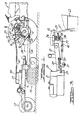
- a tractor 10 is provided with a liftable implement supporting hitch 11 and a hydraulic system for raising and lowering the hitch.
- the implement 12 which in this instance is shown as a semi-mounted disc type harrow, is attached by a tongue 13 to a drawbar 14 secured to the tractor for towing the implement.
- the implement 12 is provided with one or more gauge wheels 15 which are adapted to at least partially support the implement and regulate the degree of penetration of the harrow below the surface of the ground, thus determining the load on the tractor (towing force required).
- the gauge wheels are mounted for raising and lowering movement relative to the frame 16 of the harrow, the height of the gauge wheels being controlled by a double acting hydraulic cylinder 17.
- the basic mechanism and hydraulic system for raising and lowering the liftable implement supporting hitch is more or less conventional and has been used for a number of years in the well known Ford tractors.
- the mechanism is illustrated and explained in the aforementioned U.S. patent 3,753,467 and is shown schematically herein in Figure 4.
- the tractor 10 is provided with a lift cylinder 18 that is a single acting cylinder.
- a piston 19 within the cylinder 18 is linked by a ram arm and a connecting rod to a rockshaft 21 rotatably mounted on the tractor.
- the tractor lift cylinder 18 is operated by hydraulic fluid pressurized by a hydraulic pump 25.
- a spring 20 extending between one of the lift arms 22 and a portion of the tractor may be provided to continually bias the hitch downwardly.
- the hydraulic system described is more or less conventional and has been used for a number of years in tractors manufactured by the Ford Motor Company.
- the implement hydraulic cylinder 17 and the lift cylinder 18 are interconnected for simultaneous operation. Any movement of the lift control lever 27 ( Figure 4) that actuates the lift valve 26 to raise or lower the tractor hitch 11 also extends or retracts the remote cylinder 17 to raise or lower the rear end of the implement 12 simultaneously with the raising or lowering of the front end by the tractor hitch.
- a flow control valve 30 is responsive to tractor driveline torque as described in U.S. patent 3 ,575,241.
- the driveline torque sensing unit (not shown) is adapted to send a signal to the control valve 30 to cause the latter to change the height of the lift arms. Because of the interconnection between the implement hydraulic lift cylinder 17 and hitch lift cylinder 18, the change in height of the hitch is reflected in a change in height of the rear end of the implement 12. The result is that the signal to the control valve changes the height of the lift arms which changes the working depth of the implement to compensate for changes in draft loads.
- auxiliary services valve 28 which directs pump oil to the remote cylinder 17.
- Return oil from the remote cylinder is directed to the hydraulic power lift cylinder 18, hence raising the implement by simultaneously extending both cylinders.
- the current system in the field today has three major concerns which are detrimental to the farmer and the manufacturer.
- the first concern is the requirement of a complex series of manipulations of the controls in a predetermined sequence to phase the remote cylinder 17 with the lift cylinder 18, initially and during normal operations.
- the necessity for phasing the cylinders arises from either cylinder leaking down and getting out of phase with the other.
- the second concern is the requirement of a special size remote cylinder 17 that must be provided to the tractor customer.
- the special cylinder must match the volume of the lift cylinder 18 and must have a piston having a valve therein that opens at the end of a cylinder stroke to allow oil transfer to the lift cylinder.
- the third concern arises from the accidental overheating of the hydraulic system when the operator disconnects the remote cylinder and forgets to shift the auxiliary services valve to a position that permits return flow of oil to the lift cylinder 18.
- the implement is properly phased with the tractor when the implement is raised to full height and its rear end reaches full height slightly before its front or hitch 11 mounted end. If this does not occur, the remote cylinder 17 is said to be out of phase with the lift cylinder 18.
- the tractor operator must, with the current system, shut off all fluid flow to the auxiliary services valve and then move the hitch lift control lever 27 to a hitch fully lowered position.
- the operator When the tractor hitch lift links 24 are fully lowered, the operator must open the auxiliary services valve to fluid under pressure and then move the hitch lift control lever 27 to a hitch fully raised position. This causes the implement to be fully raised with its rear end reaching the fully raised position before the front end because of the unique valve-in-piston used in the remote cylinder.
- the present invention provides for the automatic phasing of the cylinders, the elimination of the auxiliary services valve manipulation by the operator, and the use of a standard remote cylinder in place of the "unique" remote cylinder with its "valve-in-piston" arrangement.
- a phasing valve generally designated 29, operating off the hitch lift arms 22. With the phasing valve 29, no special phasing manipulations by the operator are required either initially or during normal operation. A full raise signal by the operator will automatically phase both cylinders every time the lift control lever is moved to a full lift position.
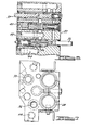
- the phasing valve 29 comprises a valve body 31 supported on a bracket 32 mounted on the cover 33 of the center housing 34 of the rear axle of the tractor.
- the valve body 31 is provided with a plurality of oil passageways, several of which accommodate valve spools.
- the two most important valve spools with reference to the present invention are the auxiliary services valve spool 35 having a stem portion 36 projecting outwardly of the right side 37 of the valve body 31, as viewed in Figure 5, and the phasing valve spool 38 having a stem portion 39 projecting outwardly of the left side 41 of the valve body 31.
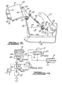
- the operation of the phasing valve 29 may best be understood with reference to two operational modes, the first of which is illustrated in Figure 6. This represents a condition in which the remote cylinder 17 is not coupled to the valve body 31 by conduits or hose connections 42 and 43 and the auxiliary service valve 35 is in an unshifted position to the right.
- a hitch 11 raise signal is initiated by the operator by manipulation of lift lever 27, flow from pump 25 is directed to the power lift cylinder 18 through oil inlet passage 44 to oil outlet passage 45 through spool passage 46 of the auxiliary services valve 35.
- phasing valve spool 38 is shifted to the right by lever 47, link 48 and lever 49.
- the lever 47 is pivotally mounted on a shaft 51 supported on the bracket 32.
- the lever 47 is pivotally coupled at its lower end 52 to the upper end 53 of link 48.
- the lower end 54 of the link 48 is pivotally coupled to the lever 49, the lower end of which is pivotal about a shaft 55 supported on the side wall 56 of the center housing 34 of the tractor axle.
- the lower end of lever 49 is fixed to a disk 57 having a radially extending projection 58 over the end 59 of an arm 61 mounted on the hub 62 of and swingable with the lift arm 22.
- both hitch lift 11 and remote cylinder 17 are in operation.
- a male coupler (not shown) on the conduit or hose 42 has an integral disk which engages the projecting end of the stem 36 of the auxiliary services valve 35 as the coupler is locked on the threaded fitting 64a on the valve body 31. This results in the auxiliary service valve spool 35 being shifted to the left.
- passage 44 is connected to passage 65 through spool passage 46.
- valve spool 38 causes passage 66 to be connected to passage 69 through spool valve passage 67. Oil flow from passage 69 is discharged into tank or reservoir 71. Passage 68 is blocked by phase valve spool 38 and as a result the lift cylinder 18 stops extending. The remote cylinder 17 continues, however, to extend until it reaches the end of its stroke. When the remote cylinder reaches the end of its stroke, pump pressure in passage 44 rises to 2200 psi, as controlled by spring 72, and shifts relief valve 73 to the right connecting passage 44 to 68. Pump flow is then directed to the hitch lift cylinder 18 to complete the extension of the latter's stroke.
- Valve spool 38 automatically shifts to the left as soon as the hitch lift cylinder 18 continues its extension because the lever 47 is returned to a neutral position by a torsional spring 74 acting through lever 49 and link 48 on lever 47 to swing the latter in a clockwise direction as viewed in Figure 2.
- the advantage of the described phasing valve is the simplicity of bringing the two cylinders 17 and 18 into phase with each other. For example, if the tractor operator notices that the remote cylinder 17 is out of phase with and lagging the lift cylinder 18, he need only operate the lift control lever 27 to bring the hitch to fully raised position. The lift cylinder 18 will stop when the hitch reaches a position two inches (five centimeters) from maximum height, the remote cylinder 17 will continue its extension until the rear end of the implement is raised to its full height, and the lift cylinder will continue its extension, bringing the hitch to full height and the system is then in phase again.
- Disconnection of the hose coupler from the phasing valve body 31 also permits the auxiliary services valve spool biased by spring 75 to automatically move back to the Figure 6 position, as explained with reference to the first operational mode.
- the pump output is merely recirculated through the tractor hydraulic system. The operator cannot forget to shift the automatic services valve as may happen with current systems in use. In current systems, failure to move the auxiliary control valve to an "off" position when disconnecting the remote cylinder may result in continuous high pressure oil flow through the hydraulic system pressure relief valve. This cannot occur with the system of this invention.
Landscapes
- Life Sciences & Earth Sciences (AREA)
- Engineering & Computer Science (AREA)
- Mechanical Engineering (AREA)
- Soil Sciences (AREA)
- Environmental Sciences (AREA)
- Zoology (AREA)
- Lifting Devices For Agricultural Implements (AREA)
Applications Claiming Priority (2)
| Application Number | Priority Date | Filing Date | Title |
|---|---|---|---|
| US317353 | 1981-11-02 | ||
| US06/317,353 US4434857A (en) | 1981-11-02 | 1981-11-02 | Tractor and implement coupled thereto with hydraulic lift system including phasing valve |
Publications (3)
| Publication Number | Publication Date |
|---|---|
| EP0078697A2 true EP0078697A2 (de) | 1983-05-11 |
| EP0078697A3 EP0078697A3 (en) | 1983-06-22 |
| EP0078697B1 EP0078697B1 (de) | 1986-05-28 |
Family
ID=23233277
Family Applications (1)
| Application Number | Title | Priority Date | Filing Date |
|---|---|---|---|
| EP82305804A Expired EP0078697B1 (de) | 1981-11-02 | 1982-11-02 | Schlepper und hydraulisches Hubsystem für Geräte |
Country Status (5)
| Country | Link |
|---|---|
| US (1) | US4434857A (de) |
| EP (1) | EP0078697B1 (de) |
| BR (1) | BR8206245A (de) |
| DE (1) | DE3271437D1 (de) |
| MX (1) | MX155692A (de) |
Cited By (3)
| Publication number | Priority date | Publication date | Assignee | Title |
|---|---|---|---|---|
| EP0494516A1 (de) * | 1991-01-11 | 1992-07-15 | Massey Ferguson S.A. | Gerätesteuerung |
| EP0507232A1 (de) * | 1991-04-05 | 1992-10-07 | Deere & Company | Steuersystem für Schlepper mit angehängtem Arbeitsgerät |
| US10542656B2 (en) | 2017-04-27 | 2020-01-28 | Cnh Industrial America Llc | Remote electrical positioning of an implement stabilizer wheel |
Families Citing this family (9)
| Publication number | Priority date | Publication date | Assignee | Title |
|---|---|---|---|---|
| US4817730A (en) * | 1988-02-16 | 1989-04-04 | Deere & Company | Hydraulic weight transfer system for an implement with a lift assist wheel |
| US5348101A (en) * | 1993-01-08 | 1994-09-20 | Deere & Company | Hydraulic system for a towed implement |
| US8282135B1 (en) * | 2009-12-17 | 2012-10-09 | Baucom Jr Donald L | Hydraulic hose coupler |
| FR3036337B1 (fr) * | 2015-05-22 | 2017-06-23 | Soc Ind De Prefabrication Electrique Siprel | Dispositif d'abaissement de la caisse d'un vehicule comportant un moyen de detection de la position haute |
| US10405478B2 (en) | 2016-11-22 | 2019-09-10 | Cnh Industrial Canada, Ltd. | Agricultural implement hydraulic rephasing unit and method |
| US20180220574A1 (en) * | 2017-02-09 | 2018-08-09 | Cnh Industrial Canada, Ltd. | Gauge wheel and hitch force control |
| DE102017121152B4 (de) * | 2017-04-24 | 2023-10-26 | Pöttinger Landtechnik Gmbh | Landwirtschaftliches Bodenbearbeitungsgerät |
| US11558990B2 (en) * | 2019-08-14 | 2023-01-24 | Cnh Industrial Canada, Ltd. | System and method for detecting a plug of a tool of a tillage implement |
| CN114568058B (zh) * | 2022-03-08 | 2022-11-29 | 宁波奔野重工股份有限公司 | 一种农用拖拉机 |
Family Cites Families (11)
| Publication number | Priority date | Publication date | Assignee | Title |
|---|---|---|---|---|
| US3575241A (en) | 1967-03-30 | 1971-04-20 | Ford Motor Co | Tractor hydraulic lift control system |
| US3517747A (en) * | 1967-08-21 | 1970-06-30 | Int Harvester Co | Automatic control means for implement |
| DE1557749B2 (de) | 1967-12-21 | 1976-03-04 | Klöckner-Humboldt-Deutz AG, 5000 Köln | Aus einem schlepper und einem aufsattelpflug bestehende arbeitseinheit |
| US3627059A (en) * | 1969-12-22 | 1971-12-14 | Deere & Co | Gauge wheel assembly for agricultural implements |
| US3756123A (en) | 1971-06-01 | 1973-09-04 | Rohr Corp | Synchronized hydraulic servo motor system |
| US3752039A (en) | 1971-12-22 | 1973-08-14 | Ibm | Master-slave hydraulic control system |
| US3753467A (en) | 1971-12-27 | 1973-08-21 | Ford Motor Co | Tractor-implement hydraulic lift system |
| US4006664A (en) | 1975-04-03 | 1977-02-08 | Pettibone Corporation | Steering system including tandem hydraulic cylinders with self-synchronization |
| US4207951A (en) | 1977-05-23 | 1980-06-17 | Peek Steven L | Two-way, multiple bottom plow with lift assist |
| US4164122A (en) | 1977-09-19 | 1979-08-14 | International Harvester Company | Cylinder construction affording automatic re-phasing of master and slave cylinders |
| US4325400A (en) | 1978-12-16 | 1982-04-20 | Wynne John R | Fluid flow equalizing valve arrangement |
-
1981
- 1981-11-02 US US06/317,353 patent/US4434857A/en not_active Expired - Lifetime
-
1982
- 1982-10-26 MX MX194933A patent/MX155692A/es unknown
- 1982-10-27 BR BR8206245A patent/BR8206245A/pt not_active IP Right Cessation
- 1982-11-02 EP EP82305804A patent/EP0078697B1/de not_active Expired
- 1982-11-02 DE DE8282305804T patent/DE3271437D1/de not_active Expired
Cited By (4)
| Publication number | Priority date | Publication date | Assignee | Title |
|---|---|---|---|---|
| EP0494516A1 (de) * | 1991-01-11 | 1992-07-15 | Massey Ferguson S.A. | Gerätesteuerung |
| US5261495A (en) * | 1991-01-11 | 1993-11-16 | Massey-Ferguson Services N.V. | Implement control |
| EP0507232A1 (de) * | 1991-04-05 | 1992-10-07 | Deere & Company | Steuersystem für Schlepper mit angehängtem Arbeitsgerät |
| US10542656B2 (en) | 2017-04-27 | 2020-01-28 | Cnh Industrial America Llc | Remote electrical positioning of an implement stabilizer wheel |
Also Published As
| Publication number | Publication date |
|---|---|
| EP0078697B1 (de) | 1986-05-28 |
| MX155692A (es) | 1988-04-13 |
| DE3271437D1 (en) | 1986-07-03 |
| EP0078697A3 (en) | 1983-06-22 |
| BR8206245A (pt) | 1983-09-20 |
| US4434857A (en) | 1984-03-06 |
Similar Documents
| Publication | Publication Date | Title |
|---|---|---|
| CA2063099C (en) | Interface system for a towed implement | |
| US4434857A (en) | Tractor and implement coupled thereto with hydraulic lift system including phasing valve | |
| US4193458A (en) | Tractor and implement and hydraulic system therefor | |
| US2611306A (en) | Power lift means affording depth control and sequential raising and lowering of implements | |
| US2394210A (en) | Coupling means for tractors | |
| US20040016556A1 (en) | Electrohydraulic control system for implement lift cylinders | |
| US7600574B2 (en) | Tractor front hitch | |
| US2521503A (en) | Coupling means for tractors | |
| US10760594B2 (en) | Hydraulic cylinder supply system | |
| US4643442A (en) | Fluid supply system for working vehicles | |
| US3917002A (en) | Draft control linkage for a tractor | |
| US2575507A (en) | Hydraulic power device | |
| US3731745A (en) | Combined draft hook operating and draft sensing | |
| CA1056262A (en) | Draft load control for tractors | |
| US3753467A (en) | Tractor-implement hydraulic lift system | |
| GB1558789A (en) | Draft load control apparatus | |
| US2887167A (en) | Hitch device | |
| US4579038A (en) | Depth control valve and system for agricultural implements | |
| US2973043A (en) | Control mechanism for tractor hydraulic systems | |
| US2970653A (en) | Hydraulic depth control apparatus | |
| EP3321515A1 (de) | Hydraulikzylinderversorgungssystem | |
| US3834738A (en) | Combined draft hook operating and draft sensing | |
| US3183977A (en) | Tractor power lift system | |
| US3182729A (en) | Hydraulic implement control for tractors | |
| US3132699A (en) | Safety release and switch out mechanism for hydraulic system |
Legal Events
| Date | Code | Title | Description |
|---|---|---|---|
| PUAI | Public reference made under article 153(3) epc to a published international application that has entered the european phase |
Free format text: ORIGINAL CODE: 0009012 |
|
| PUAL | Search report despatched |
Free format text: ORIGINAL CODE: 0009013 |
|
| AK | Designated contracting states |
Designated state(s): BE DE FR GB NL SE |
|
| AK | Designated contracting states |
Designated state(s): BE DE FR GB NL SE |
|
| 17P | Request for examination filed |
Effective date: 19831104 |
|
| GRAA | (expected) grant |
Free format text: ORIGINAL CODE: 0009210 |
|
| AK | Designated contracting states |
Kind code of ref document: B1 Designated state(s): BE DE FR GB NL SE |
|
| REF | Corresponds to: |
Ref document number: 3271437 Country of ref document: DE Date of ref document: 19860703 |
|
| ET | Fr: translation filed | ||
| REG | Reference to a national code |
Ref country code: GB Ref legal event code: 746 |
|
| PLBE | No opposition filed within time limit |
Free format text: ORIGINAL CODE: 0009261 |
|
| STAA | Information on the status of an ep patent application or granted ep patent |
Free format text: STATUS: NO OPPOSITION FILED WITHIN TIME LIMIT |
|
| 26N | No opposition filed | ||
| PGFP | Annual fee paid to national office [announced via postgrant information from national office to epo] |
Ref country code: NL Payment date: 19871130 Year of fee payment: 6 |
|
| REG | Reference to a national code |
Ref country code: FR Ref legal event code: DL |
|
| PGFP | Annual fee paid to national office [announced via postgrant information from national office to epo] |
Ref country code: BE Payment date: 19890222 Year of fee payment: 7 |
|
| PG25 | Lapsed in a contracting state [announced via postgrant information from national office to epo] |
Ref country code: BE Effective date: 19891130 |
|
| BERE | Be: lapsed |
Owner name: FORD MOTOR CY Effective date: 19891130 |
|
| PG25 | Lapsed in a contracting state [announced via postgrant information from national office to epo] |
Ref country code: NL Effective date: 19900601 |
|
| NLV4 | Nl: lapsed or anulled due to non-payment of the annual fee | ||
| PGFP | Annual fee paid to national office [announced via postgrant information from national office to epo] |
Ref country code: SE Payment date: 19901101 Year of fee payment: 9 |
|
| PG25 | Lapsed in a contracting state [announced via postgrant information from national office to epo] |
Ref country code: SE Effective date: 19911103 |
|
| PGFP | Annual fee paid to national office [announced via postgrant information from national office to epo] |
Ref country code: GB Payment date: 19911115 Year of fee payment: 10 |
|
| PGFP | Annual fee paid to national office [announced via postgrant information from national office to epo] |
Ref country code: FR Payment date: 19911119 Year of fee payment: 10 |
|
| PGFP | Annual fee paid to national office [announced via postgrant information from national office to epo] |
Ref country code: DE Payment date: 19911129 Year of fee payment: 10 |
|
| PG25 | Lapsed in a contracting state [announced via postgrant information from national office to epo] |
Ref country code: GB Effective date: 19921102 |
|
| REG | Reference to a national code |
Ref country code: GB Ref legal event code: 732 |
|
| REG | Reference to a national code |
Ref country code: FR Ref legal event code: TP |
|
| GBPC | Gb: european patent ceased through non-payment of renewal fee |
Effective date: 19921102 |
|
| PG25 | Lapsed in a contracting state [announced via postgrant information from national office to epo] |
Ref country code: FR Effective date: 19930730 |
|
| PG25 | Lapsed in a contracting state [announced via postgrant information from national office to epo] |
Ref country code: DE Effective date: 19930803 |
|
| REG | Reference to a national code |
Ref country code: FR Ref legal event code: ST |
|
| EUG | Se: european patent has lapsed |
Ref document number: 82305804.5 Effective date: 19920604 |