EP0078570B1 - Device for orienting pieces of work, more especially brush bodies - Google Patents
Device for orienting pieces of work, more especially brush bodies Download PDFInfo
- Publication number
- EP0078570B1 EP0078570B1 EP19820201332 EP82201332A EP0078570B1 EP 0078570 B1 EP0078570 B1 EP 0078570B1 EP 19820201332 EP19820201332 EP 19820201332 EP 82201332 A EP82201332 A EP 82201332A EP 0078570 B1 EP0078570 B1 EP 0078570B1
- Authority
- EP
- European Patent Office
- Prior art keywords
- work
- piece
- piston
- feeler
- frame
- Prior art date
- Legal status (The legal status is an assumption and is not a legal conclusion. Google has not performed a legal analysis and makes no representation as to the accuracy of the status listed.)
- Expired
Links
- 210000000078 claw Anatomy 0.000 claims description 12
- 238000006073 displacement reaction Methods 0.000 claims description 11
- 238000003825 pressing Methods 0.000 claims description 11
- 238000003860 storage Methods 0.000 claims description 4
- 210000004209 hair Anatomy 0.000 description 1
- 238000004519 manufacturing process Methods 0.000 description 1
- 238000000034 method Methods 0.000 description 1
Images


Classifications
-
- A—HUMAN NECESSITIES
- A46—BRUSHWARE
- A46D—MANUFACTURE OF BRUSHES
- A46D3/00—Preparing, i.e. Manufacturing brush bodies
- A46D3/08—Parts of brush-making machines
-
- B—PERFORMING OPERATIONS; TRANSPORTING
- B23—MACHINE TOOLS; METAL-WORKING NOT OTHERWISE PROVIDED FOR
- B23Q—DETAILS, COMPONENTS, OR ACCESSORIES FOR MACHINE TOOLS, e.g. ARRANGEMENTS FOR COPYING OR CONTROLLING; MACHINE TOOLS IN GENERAL CHARACTERISED BY THE CONSTRUCTION OF PARTICULAR DETAILS OR COMPONENTS; COMBINATIONS OR ASSOCIATIONS OF METAL-WORKING MACHINES, NOT DIRECTED TO A PARTICULAR RESULT
- B23Q7/00—Arrangements for handling work specially combined with or arranged in, or specially adapted for use in connection with, machine tools, e.g. for conveying, loading, positioning, discharging, sorting
- B23Q7/16—Loading work on to conveyors; Arranging work on conveyors, e.g. varying spacing between individual workpieces
- B23Q7/165—Turning devices
-
- B—PERFORMING OPERATIONS; TRANSPORTING
- B65—CONVEYING; PACKING; STORING; HANDLING THIN OR FILAMENTARY MATERIAL
- B65G—TRANSPORT OR STORAGE DEVICES, e.g. CONVEYORS FOR LOADING OR TIPPING, SHOP CONVEYOR SYSTEMS OR PNEUMATIC TUBE CONVEYORS
- B65G47/00—Article or material-handling devices associated with conveyors; Methods employing such devices
- B65G47/22—Devices influencing the relative position or the attitude of articles during transit by conveyors
- B65G47/24—Devices influencing the relative position or the attitude of articles during transit by conveyors orientating the articles
- B65G47/244—Devices influencing the relative position or the attitude of articles during transit by conveyors orientating the articles by turning them about an axis substantially perpendicular to the conveying plane
Definitions
- the present invention relates to a device for orienting pieces of work, especially brush bodies, in other words a device the purpose of which is to correctly orient pieces of work in orderto be able to deliver these pieces of work in a suitable position to the processing machine properly speaking.
- the present invention relates to a device which is intended for orienting pieces of work as are brush bodies, in other words for locating these pieces of work, for instance in the case of brush bodies, at least with the little holes in one and the same direction, whereby, if one has to process brush bodies the little holes of which are not symmetrically located, as, for instance, is the case of tooth brushes, the brush bodies can also be turned in the length.
- Such a device according to the invention can, of course, be used as well alone as directly in combination with a processing machine.
- the device according to the invention is of the type whereby, from a storage container, by means of a conveyor, pieces of work are fed one by one, and is provided with means each of which can exert action upon an end of the piece of work in order to seize same, means which can give the aforesaid means a displacement with respect to the framework of the machine, means which in the course of the aforesaid displacement detect the position of the piece of work concerned and means which allow to impart to the piece of work a 180 degrees rotation about its longitudinal axis, this device (known from EP-A-0078570 of the applicant) being characterized in that also means are provided which allow to impart to the piece of work a 180 degress rotation about an axis which is perpendicular to the longitudinal axis of the piece of work, these means being formed, at the one hand, by a pressure cylinder the outgoing piston rod of which is provided with claws which can be opened or closed through a displacement of the piston of said cylinder, and between which the piece of work can be seized in the middle
- the device as shown in the attached drawings is intended for detecting in an appropriate way tooth brush bodies, in which little holes have been previously made, and to turn same, in the present case, about an horizontal and a vertical axis, in such a way that all the brush bodies are positioned in the same way, so that the brush bodies can be arranged absolutely at random in a storage container, after which, before being conveyed to the processing machine for planting the fibres, they become oriented if necessary by means of the device according to the invention.
- the device according to the invention is mounted near to a conveyor, in the present case a drum 1 with therein circumferentially located grooves 2, each of which is apt to receive a brush body 3.
- a drum 1 which is known in itself, it is possible to extract the brush bodies 3 from an appropriate container in order, via the detecting means according to the invention, to deliver same to the processing machine.
- the brush bodies 3 are arranged at random in the aforesaid container and are taken up by the drum 1 as follows.
- the device according to the invention mainly consists of a frame 4 which, via suitable guides, 5 and 6 respectively, is slidably mounted, vertically in this case, with respect to the framework 7, which is schematically indicated, whereby between the parts 4 and 7 two pneumatic cylinders, 8 and 9 respectively, are provided for, which are assembled together and whereby the pistons, 10 and 11 respectively, of these cylinders, are suitably assembled with the framework 7 and the frame 4.
- a pinion 24 is fixed in this case, showing a width which is equal to or a little greater than the maximum displacement of the piston 19, whereby a toothed rack 25 is constantly in mesh with this pinion toothed rack which is fixed on the free end of a piston rod 26, the piston 27 of which is a part of a cylinder 28 fixed on the arm 15 of the frame 4.
- the device according to the invention is being further completed by a pressure cylinder 29, which is fixed on the framework 7, the piston 30 of which, via a piston rod 31, is assembled with a toothed rack 32 which is in constant mesh with a pinion 33 the rotation shaft 34 of which is suitably assembled to a cylinder 35.
- the piston 36 of the latter, via the piston rod 37, is provided with claws, 38 and 39 respectively, which can seize the brush body 3 in an appropriate way, as will be explained hereinafter.
- feelers or palpating components, 40 and 41 respectively are also provided for, which are apt to suitably operate switching means, 42 and 43 respectively.
- the operation of the device according to the invention is very simple and as follows.
- the brush bodies 3 which, in the present case, show in the zone of the brush hairs a heightened part 44 wherein the little holes 45 are made, are placed at random in a storage container, from where the drum 1 or another conveyor which is known in itself, takes up the brush bodies.
- these brush bodies can be located in the grooves 2 of such a device 1 in four different ways, say with the part 44 oriented to the right in the drawings and the little holes 45 upwards; with the part 44 oriented to the right and the little holes 45 downwards; with the part 44 oriented to the left and the little holes 45 upwards and finally with the part 44 oriented to the left and the little holes 45 downwards, whereby in the example shown it is the position with the part 44 to the right and the little holes 45 upwards that is the position wherein the brush body is to be delivered to the manufacturing machine.
- Ther drum 1 has, for instance, a constant drive motion and only stops when a brush body 3 is being placed between the pressing components 22 and 23, this situation being controlled by a photo-electric cell or similar component 46.
- the little brush is located on the drum 1 with the part 44 to the right in the drawings and with the little holes45 oriented downwards.
- the components 22 and 23 will also clamp the brush body, after which the pistons 10 and 11 will be operated so that the frame 4 will come into its highest position, whereby, in this case, during this displacement, both the components 40 and 41 will be pushed in, whereby there is obtained that the pistons 10 and 11 are operated to bring the frame 4 and the brush body 3 again in the lowest position, whereby during the downwards motion, piston 27 becomes also pushed out in order to obtain that via the toothed rack 25 and pinion 24 the brush body obtains a rotative motion of 180° about its longitudinal axis.
- the pistons 18 and 19 are being commanded so that the components 22 and 23 seize a brush body. Then the pistons 10 and 11 are being commanded in order to obtain that the frame 4 comes into its highest position, whereby, in this highest position, neither the palpating component or feeler 40 nor the palpating component or feeler 41 are influenced, so that a command is being given to the piston 10, which brings the frame 4 in an intermediate position whereby-the brush body is placed between the claws 38, 39, after which the piston 36 is being pushed out in order to close the claws 38 and 39 and to seize the brush body.
- cylinder 10 becomes operated, see Figure 4, and after operating respectively the piston 36, which results in closing the claws 38 and 39, and operating the piston 30, which results in a 180° rotation of the cylinder 35, the position is reached as shown in Figure 4, after which the brush body, by means of the components 22 and 23 is being seized again and both the feeler components 40 and 41 are influenced which operate the switching components 42 and 43.
- the pistons 18 and 19 are finally operated, due to which the brush body is liberated and the pistons 27 and 30 will be operated in order to bring them both into their starting position.
- the feelers may have any shape, depending on the shape of the brush body, whereby, in the case of a truly rectangular flat brush body, which may be considered as an extreme case, the feelers 40 and 41 shall be made in such a way that they perform the palpating operations through acting in the little holes 45.
Landscapes
- Engineering & Computer Science (AREA)
- Mechanical Engineering (AREA)
- Manufacturing & Machinery (AREA)
- Manipulator (AREA)
Description
- The present invention relates to a device for orienting pieces of work, especially brush bodies, in other words a device the purpose of which is to correctly orient pieces of work in orderto be able to deliver these pieces of work in a suitable position to the processing machine properly speaking.
- More especially, the present invention relates to a device which is intended for orienting pieces of work as are brush bodies, in other words for locating these pieces of work, for instance in the case of brush bodies, at least with the little holes in one and the same direction, whereby, if one has to process brush bodies the little holes of which are not symmetrically located, as, for instance, is the case of tooth brushes, the brush bodies can also be turned in the length.
- In this way one obtainsthatthe person attending the processing machine must no more put the pieces of work in the machine in the correct position, in such a way that the constant presence of this person attending the machine is no more required and that this person not only can divide her attention between a number of machines, but can also assume supplementary tasks as are, for instance, the control of the products turned out and/or of their package.
- Such a device according to the invention can, of course, be used as well alone as directly in combination with a processing machine.
- The device according to the invention is of the type whereby, from a storage container, by means of a conveyor, pieces of work are fed one by one, and is provided with means each of which can exert action upon an end of the piece of work in order to seize same, means which can give the aforesaid means a displacement with respect to the framework of the machine, means which in the course of the aforesaid displacement detect the position of the piece of work concerned and means which allow to impart to the piece of work a 180 degrees rotation about its longitudinal axis, this device (known from EP-A-0078570 of the applicant) being characterized in that also means are provided which allow to impart to the piece of work a 180 degress rotation about an axis which is perpendicular to the longitudinal axis of the piece of work, these means being formed, at the one hand, by a pressure cylinder the outgoing piston rod of which is provided with claws which can be opened or closed through a displacement of the piston of said cylinder, and between which the piece of work can be seized in the middle thereof, and at the other hand by the cooperation of a toothed rack with a pinion, which is provided for on the aforesaid pressure cylinder, whilst the toothed rack is provided at the free end of the piston rod of a pressure cylinderwhich is mounted on the frame of the device.
- In order better to show the characteristics of the invention, a preferred embodiment is described hereinafter, without any limitative character, reference being made to the attached drawings wherein:
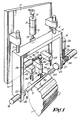
- Figure 1 shows a schematic perspective view of a device according to the invention;
- Figures 2 through 7 show various positions of the device according to the invention;
- Figures 8 and 9 show sections according to the lines VIII-VIII and IX-IX in Figure 3 respectively;
- Figures 10 and 11 show sections according to lines X-X and XI-XI in Figure 5 respectively.
- The device as shown in the attached drawings is intended for detecting in an appropriate way tooth brush bodies, in which little holes have been previously made, and to turn same, in the present case, about an horizontal and a vertical axis, in such a way that all the brush bodies are positioned in the same way, so that the brush bodies can be arranged absolutely at random in a storage container, after which, before being conveyed to the processing machine for planting the fibres, they become oriented if necessary by means of the device according to the invention.
- For this purpose, the device according to the invention is mounted near to a conveyor, in the present case a drum 1 with therein circumferentially located
grooves 2, each of which is apt to receive abrush body 3. By means of such a drum 1, which is known in itself, it is possible to extract thebrush bodies 3 from an appropriate container in order, via the detecting means according to the invention, to deliver same to the processing machine. - The
brush bodies 3 are arranged at random in the aforesaid container and are taken up by the drum 1 as follows. - The device according to the invention mainly consists of a
frame 4 which, via suitable guides, 5 and 6 respectively, is slidably mounted, vertically in this case, with respect to theframework 7, which is schematically indicated, whereby between theparts framework 7 and theframe 4. - On the arms, 14 and 15 respectively, of the
U-shaped frame 4, cylinders, 16 and 17 respectively, are mounted, the pistons of which, 18 and 19 respectively, via thepiston rods suitable components - On the
piston rod 21 of thecylinder 17, apinion 24 is fixed in this case, showing a width which is equal to or a little greater than the maximum displacement of thepiston 19, whereby atoothed rack 25 is constantly in mesh with this pinion toothed rack which is fixed on the free end of apiston rod 26, thepiston 27 of which is a part of acylinder 28 fixed on thearm 15 of theframe 4. - The device according to the invention is being further completed by a
pressure cylinder 29, which is fixed on theframework 7, thepiston 30 of which, via apiston rod 31, is assembled with atoothed rack 32 which is in constant mesh with apinion 33 therotation shaft 34 of which is suitably assembled to acylinder 35. Thepiston 36 of the latter, via thepiston rod 37, is provided with claws, 38 and 39 respectively, which can seize thebrush body 3 in an appropriate way, as will be explained hereinafter. - On each side of the
device 33 through 39, feelers or palpating components, 40 and 41 respectively, are also provided for, which are apt to suitably operate switching means, 42 and 43 respectively. - The operation of the device according to the invention is very simple and as follows.
- The
brush bodies 3 which, in the present case, show in the zone of the brush hairs a heightenedpart 44 wherein thelittle holes 45 are made, are placed at random in a storage container, from where the drum 1 or another conveyor which is known in itself, takes up the brush bodies. - One obtains in this way that these brush bodies can be located in the
grooves 2 of such a device 1 in four different ways, say with thepart 44 oriented to the right in the drawings and thelittle holes 45 upwards; with thepart 44 oriented to the right and thelittle holes 45 downwards; with thepart 44 oriented to the left and thelittle holes 45 upwards and finally with thepart 44 oriented to the left and thelittle holes 45 downwards, whereby in the example shown it is the position with thepart 44 to the right and thelittle holes 45 upwards that is the position wherein the brush body is to be delivered to the manufacturing machine. - Ther drum 1 has, for instance, a constant drive motion and only stops when a
brush body 3 is being placed between thepressing components similar component 46. - At this moment the
pistons brush body 3, whereby thepressing components pressing components - Subsequently, the
pistons frame 4 becomes placed in its highest position. - In this position, the brush body, at this moment, comes against the
feeler 40, which influences theswitching component 42, whilst thefeeler 41 is not being influenced. - Due to the fact that
component 43 does not switch and that thecomponent 42 does switch, a command is first given to thepistons frame 4 into its lowest position, whereby the brush body is put back into agroove 2, after which thepistons component 46. - Let us suppose that in this case the little brush is located on the drum 1 with the
part 44 to the right in the drawings and with the little holes45 oriented downwards. - In this case, the
components pistons frame 4 will come into its highest position, whereby, in this case, during this displacement, both thecomponents pistons frame 4 and thebrush body 3 again in the lowest position, whereby during the downwards motion,piston 27 becomes also pushed out in order to obtain that via thetoothed rack 25 andpinion 24 the brush body obtains a rotative motion of 180° about its longitudinal axis. - Afterthe brush body has been placed in a
groove 2, thepressing components piston 27 will be brought again into its retracted position. - When between the
pressing components 22 and 23 a brush body is placed thepart 44 of which is oriented to the left with thelittle holes 45 oriented upwards, the following components will function successively. - The
pistons components pistons frame 4 comes into its highest position, whereby, in this highest position, neither the palpating component orfeeler 40 nor the palpating component orfeeler 41 are influenced, so that a command is being given to thepiston 10, which brings theframe 4 in an intermediate position whereby-the brush body is placed between theclaws piston 36 is being pushed out in order to close theclaws pistons piston 30 receives the command to impart to the claws a rotation of 180° via thetoothed rack 32 andpinion 33. At this moment, thepistons pressing components piston 36, theclaws piston 10, theframe 4 is brought again in the high position, resulting atthat moment in thepalpating component 40 being pushed in and palpatingcomponents 41 not being pushed in, which, as in the first example, results in bothpistons frame 4 is being placed in its lowest position; thepistons piston 30 is being operated again in order to place the toothed rack in its original position. - When finally we take into consideration the fourth possibility, wherein the brush body is located in a
groove 2 with thepart 44 oriented to the left in the drawings and the little holes of the brush oriented downwards, situation which is shown in the Figures 2 through 11, and from where the situations mentioned hereinabove can be deduced, one obtains that in a first stage thepressing components pistons frame 4 in its highest position. Subsequently,cylinder 10 becomes operated, see Figure 4, and after operating respectively thepiston 36, which results in closing theclaws piston 30, which results in a 180° rotation of thecylinder 35, the position is reached as shown in Figure 4, after which the brush body, by means of thecomponents feeler components switching components pistons frame 4 moves downwards, whereby during this motion thepiston 27 is being also operated, whereby one obtains that before the brush body is placed back into the drum 1, this brush body is being rotated over 180° about its longitudinal axis. At this moment, thepistons pistons - As clearly appears from the preceding explanations, one obtains in this way a palpating device, whereby, depending on the position of the brush body, two
feeler components - It is clear that the feelers may have any shape, depending on the shape of the brush body, whereby, in the case of a truly rectangular flat brush body, which may be considered as an extreme case, the
feelers little holes 45. - The reason why at least the
piston 30 always moves backto its original position isthatwhen one has to do with brush bodies which seen from above have not a straight shape, which is mostly the case, theclaws - It is clear that the present invention is not at all limited to the embodiments described as examples and illustrated in the attached drawings.
Claims (14)
Applications Claiming Priority (2)
| Application Number | Priority Date | Filing Date | Title |
|---|---|---|---|
| BE2059449 | 1981-11-04 | ||
| BE2/59449A BE890970A (en) | 1981-11-04 | 1981-11-04 | DEVICE FOR ORIENTING WORKPIECES MORE SPECIAL BRUSH BODIES |
Publications (3)
| Publication Number | Publication Date |
|---|---|
| EP0078570A2 EP0078570A2 (en) | 1983-05-11 |
| EP0078570A3 EP0078570A3 (en) | 1985-11-06 |
| EP0078570B1 true EP0078570B1 (en) | 1988-01-27 |
Family
ID=3865578
Family Applications (1)
| Application Number | Title | Priority Date | Filing Date |
|---|---|---|---|
| EP19820201332 Expired EP0078570B1 (en) | 1981-11-04 | 1982-10-26 | Device for orienting pieces of work, more especially brush bodies |
Country Status (2)
| Country | Link |
|---|---|
| EP (1) | EP0078570B1 (en) |
| DE (1) | DE3278030D1 (en) |
Families Citing this family (4)
| Publication number | Priority date | Publication date | Assignee | Title |
|---|---|---|---|---|
| DE3583672D1 (en) * | 1985-01-07 | 1991-09-05 | Boucherie Nv G B | DEVICE FOR LOADING A WORKPIECE HOLDER BY BRUSH BODY FROM A FEEDING DEVICE. |
| BE1012348A3 (en) * | 1997-09-25 | 2000-10-03 | Zahoransky Anton Gmbh & Co | Brush manufacturing machine |
| KR102013681B1 (en) * | 2018-08-22 | 2019-08-23 | (주)유비테크 | Assembly device for drum brush assembly for vacuum cleaner |
| CN111838958B (en) * | 2020-07-27 | 2022-02-18 | 深圳市美怡雅化妆用具有限公司 | Cosmetic brush filling machine |
Family Cites Families (2)
| Publication number | Priority date | Publication date | Assignee | Title |
|---|---|---|---|---|
| DE2650041A1 (en) * | 1976-10-30 | 1978-05-11 | Zahoransky Anton Fa | Fully automated tooth-brush mfg. machine - has conveyor system leading brushes from bristle tufting machine to finishing machine |
| DE2922290A1 (en) * | 1979-05-31 | 1980-12-04 | Boucherie Nv G B | DEVICE FOR ORIENTING WORKPIECES, ESPECIALLY BRUSHED BODIES |
-
1982
- 1982-10-26 EP EP19820201332 patent/EP0078570B1/en not_active Expired
- 1982-10-26 DE DE8282201332T patent/DE3278030D1/en not_active Expired
Also Published As
| Publication number | Publication date |
|---|---|
| EP0078570A3 (en) | 1985-11-06 |
| EP0078570A2 (en) | 1983-05-11 |
| DE3278030D1 (en) | 1988-03-03 |
Similar Documents
| Publication | Publication Date | Title |
|---|---|---|
| US4869025A (en) | Grinding machine, in particular for grinding scissors parts | |
| IT9048333A1 (en) | APPARATUS FOR THE PROCESSING OF TIMBER. | |
| US4801235A (en) | Device for handling workpieces | |
| EP0078570B1 (en) | Device for orienting pieces of work, more especially brush bodies | |
| IT9019945A1 (en) | MACHINE TOOL, IN PARTICULAR PRECISION GRINDING MACHINE | |
| EP2153954B1 (en) | Automatic working centre for frame pieces | |
| US3412995A (en) | Ram drive mechanism | |
| US3198349A (en) | Loading device for machine working on tubular workpieces | |
| US3951272A (en) | Article transfer apparatus | |
| US4231212A (en) | Valve bag feeding method and machine for powder material packaging apparatus | |
| EP0041636B1 (en) | Apparatus for feeding along two parallel rows articles to be moulded | |
| US4683649A (en) | Device for assembling return bend to coil | |
| US4255075A (en) | Loader | |
| US4048838A (en) | Arrangement for controllably reciprocating a workpiece gripping assembly of a multi-stage press | |
| US4747208A (en) | Device for assembling return bend to coil | |
| GB2006076A (en) | Conveying workpieces | |
| EP0026370A2 (en) | Device for inserting bars into tubes | |
| US4603912A (en) | Brush manufacturing machine | |
| US3292798A (en) | Linear transport and placement device for a workpiece | |
| US3440855A (en) | Machine to unfold the winding coils of electrical machines | |
| JPS6347526B2 (en) | ||
| ITBO970432A1 (en) | TOWER PUNCHING MACHINE. | |
| SU1620174A1 (en) | Automatic device for stamping articles of stepped shape | |
| JPS6010821B2 (en) | Automatic feeding device of press machine | |
| JPS6141651B2 (en) |
Legal Events
| Date | Code | Title | Description |
|---|---|---|---|
| PUAI | Public reference made under article 153(3) epc to a published international application that has entered the european phase |
Free format text: ORIGINAL CODE: 0009012 |
|
| AK | Designated contracting states |
Designated state(s): DE FR GB IT |
|
| PUAL | Search report despatched |
Free format text: ORIGINAL CODE: 0009013 |
|
| AK | Designated contracting states |
Designated state(s): DE FR GB IT |
|
| 17P | Request for examination filed |
Effective date: 19851209 |
|
| 17Q | First examination report despatched |
Effective date: 19861209 |
|
| GRAA | (expected) grant |
Free format text: ORIGINAL CODE: 0009210 |
|
| AK | Designated contracting states |
Kind code of ref document: B1 Designated state(s): DE FR GB IT |
|
| ITF | It: translation for a ep patent filed | ||
| REF | Corresponds to: |
Ref document number: 3278030 Country of ref document: DE Date of ref document: 19880303 |
|
| ET | Fr: translation filed | ||
| PG25 | Lapsed in a contracting state [announced via postgrant information from national office to epo] |
Ref country code: GB Effective date: 19881026 |
|
| PLBE | No opposition filed within time limit |
Free format text: ORIGINAL CODE: 0009261 |
|
| STAA | Information on the status of an ep patent application or granted ep patent |
Free format text: STATUS: NO OPPOSITION FILED WITHIN TIME LIMIT |
|
| 26N | No opposition filed | ||
| PG25 | Lapsed in a contracting state [announced via postgrant information from national office to epo] |
Ref country code: FR Free format text: LAPSE BECAUSE OF NON-PAYMENT OF DUE FEES Effective date: 19890630 |
|
| PG25 | Lapsed in a contracting state [announced via postgrant information from national office to epo] |
Ref country code: DE Effective date: 19890701 |
|
| GBPC | Gb: european patent ceased through non-payment of renewal fee | ||
| REG | Reference to a national code |
Ref country code: FR Ref legal event code: ST |