EP0078561A2 - Freikolbenbrennkraftmaschine mit unabhängig getriebenem Nocken - Google Patents
Freikolbenbrennkraftmaschine mit unabhängig getriebenem Nocken Download PDFInfo
- Publication number
- EP0078561A2 EP0078561A2 EP82201290A EP82201290A EP0078561A2 EP 0078561 A2 EP0078561 A2 EP 0078561A2 EP 82201290 A EP82201290 A EP 82201290A EP 82201290 A EP82201290 A EP 82201290A EP 0078561 A2 EP0078561 A2 EP 0078561A2
- Authority
- EP
- European Patent Office
- Prior art keywords
- cam
- pistons
- engine
- motor
- independent
- Prior art date
- Legal status (The legal status is an assumption and is not a legal conclusion. Google has not performed a legal analysis and makes no representation as to the accuracy of the status listed.)
- Granted
Links
Images


Classifications
-
- F—MECHANICAL ENGINEERING; LIGHTING; HEATING; WEAPONS; BLASTING
- F02—COMBUSTION ENGINES; HOT-GAS OR COMBUSTION-PRODUCT ENGINE PLANTS
- F02B—INTERNAL-COMBUSTION PISTON ENGINES; COMBUSTION ENGINES IN GENERAL
- F02B75/00—Other engines
- F02B75/04—Engines with variable distances between pistons at top dead-centre positions and cylinder heads
-
- F—MECHANICAL ENGINEERING; LIGHTING; HEATING; WEAPONS; BLASTING
- F02—COMBUSTION ENGINES; HOT-GAS OR COMBUSTION-PRODUCT ENGINE PLANTS
- F02B—INTERNAL-COMBUSTION PISTON ENGINES; COMBUSTION ENGINES IN GENERAL
- F02B71/00—Free-piston engines; Engines without rotary main shaft
- F02B71/04—Adaptations of such engines for special use; Combinations of such engines with apparatus driven thereby
-
- F—MECHANICAL ENGINEERING; LIGHTING; HEATING; WEAPONS; BLASTING
- F02—COMBUSTION ENGINES; HOT-GAS OR COMBUSTION-PRODUCT ENGINE PLANTS
- F02B—INTERNAL-COMBUSTION PISTON ENGINES; COMBUSTION ENGINES IN GENERAL
- F02B63/00—Adaptations of engines for driving pumps, hand-held tools or electric generators; Portable combinations of engines with engine-driven devices
- F02B63/04—Adaptations of engines for driving pumps, hand-held tools or electric generators; Portable combinations of engines with engine-driven devices for electric generators
- F02B63/041—Linear electric generators
Definitions
- the present invention relates to an internal combustion engine with free pistons, especially for the actuation of a linear alternator, comprising at least one pair of opposite cylinders whose pistons are reciprocally connected by a rod connected in an intermediate point to the moving element of a linear alternator or other means of using the energy produced.
- the present invention aims to achieve a free piston engine suitable for being coupled to a generator with linear alternator, which is completely devoid of linkages and gears intended to transmit the mechanical energy produced, and in which however are ensured the execution of the compression stroke even in the event of a lack of combustion, the execution by the pistons of a stroke extending between limits prefixed with precision, and the possibility, in the case of engines with several units, easy synchronization.
- an engine of the type considered comprises at least one cam actuated by an independent engine, in a substantially synchronous manner with the displacements of the piston rod, and engaging with pusher means connected to the piston rod, so as not to give rise to a substantial transmission of energy during normal operation, but to limit the travel of the pistons and to transfer to them the energy necessary for compression in the event of abnormal operation of the free piston engine.
- the rod of the unit, and consequently the relative pistons are forced to move within the limits and according to the law of movement preset by the cam actuated by its own independent motor.
- the cam profile and by adjusting its actuation speed adequately, there is the possibility of ensuring that, during normal operation, the law of movement imposed by the cam coincides with the movement spontaneous of the free piston unit, so that no transfer of energy takes place between the cam (and therefore its independent motor) and the pusher (and therefore the free piston motor).
- the presence of the cam positively prevents that, due to any malfunction of the functioning, the free pistons can exceed the stroke limits which have been assigned to it, and, in the event of an accidental omission of one or more combustions, the cam intervenes by driving, by the pusher, the rod of the unit and thus making accomplish the compression stroke which otherwise could not have taken place.
- the cam in the case of engines having several units, it suffices to establish synchronization between the respective cams, to obtain complete synchronization of the different units.
- a free piston engine according to the invention gives a handsome overall yield blow larger than that of traditional piston engines and even somewhat higher than that of turbines of the same power; a strong economy is also achievable in the consumption of lubricating oil, while the reduced pollution characteristics of free piston engines can be exploited in the most favorable way.
- the cam with independent engine can be used for starting the engine, if it is considered appropriate, as an alternative to compressed air systems or for the temporary use, as engine, of the linear alternator, systems known to present for free piston engines.
- the invention also relates to special arrangements for an engine of the indicated type, and in particular a magnetic support for the elimination of the load applied to the walls of the cylinders, in large engines, because of the weight of the moving parts; and provisions for correct operation in engines with coal dust or other solid fuel feed.
- auxiliary service parts such as the lights, the valves, the injectors, the washing, cooling and lubrication means, and so on, parts thereof which belong to the known technique and do not need to be modified for the application of the invention.
- the unit shown in Figure 1 comprises two opposite cylinders and 2, in which are arranged the pistons, 3 and 4 respectively, rigidly connected to each other by a rod 5 which, in an intermediate point, supports the means d 'use, in this case inductor 6; for example with permanent magnet, of a linear alternator 7.
- These parts form a free piston engine with electric generator, of a type which by itself has already been proposed by the same applicant, in which the compression stroke of each cylinder is activated by the trigger in the opposite cylinder, so that in normal operation it is not necessary to use auxiliary means to activate compression, while the stroke limits are imposed (but not rigidly) by the compressive strength of the mixture intended to give rise to successive combustion.
- a cam 11 is provided, carried and actuated by an independent eccentric motor 9, and engaging with a pusher secured to rod 5 of the unit.
- This pusher may be constituted by a pair of robust pins 8, possibly with rollers, or by a groove in the rod 5 or other equivalent means; the cam is illustrated as having a circular profile, but it is understood that its profile can be preset in an appropriate manner for the best operation of the free piston engine.
- the independent motor 9 is controlled in such a way that the rotation of the cam 11 is substantially synchronous with the operation of the free piston engine, so that in normal operation the engagement between the cam 11 and the pusher 8 is only virtual and does not involve any resistance or transmission of energy.
- the rod 5 tends not to stop at the preset stroke limit, the contact between the pusher and the cam becomes active and the stroke of the rod 5, with the pistons 3 and 4, is positively limited.
- the pusher 8 enters into active cooperation with the cam 11, and the independent motor 9 of the latter provides the energy necessary to effect the compression, thus avoiding the stopping of the free piston engine.
- starting the free piston engine can be carried out by the independent engine 9 when it is not desired to use compressed air systems or to use the linear alternator as a starting engine, as is customary for free piston engines.
- the independent motor 9 is controlled so that the cam 11 tends to slightly advance relative to the movement of the pusher 8, thereby avoiding any obstacle, under normal conditions, to the movement of the rod 5 and, by therefore, the operation of the free piston engine.
- the cam 11 is provided with a balancing mass 10. This mass can be modified with respect to what is necessary for the balancing of the cam itself, with the aim of achieving partial balancing of the free piston engine, which by itself is not balanced.
- the independent motor 9 must be of a type capable of providing greater torque if necessary, without appreciably changing its own speed. It may therefore be a bypass excitation motor, a metasearch engine or an electric motor provided with an appropriate electronic control device. Appropriate means can be used to disconnect the linear alternator during the periods in which the independent engine 9 must face the functional shortcomings of the free piston engine, so as to limit the load applied to the independent engine.
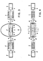
- Figures 3 and 4 show an arrangement of two units similar to that shown in Figures 1 and 2, which in itself is balanced and requires a single cam for the service of the two units, further establishing a rigid synchronism between them.
- the two units of which the one on the right is indicated by the same references of the unit described above, and the one on the left is indicated by corresponding references provided with an apex, are arranged symmetrically, with the pistons 3 and 3 ' opposite one another in a single central cylinder 1 '; the cam 12 (which in this case cannot be circular but must be substantially elliptical or oval) has at least one axis of symmetry and cooperates with the two pushers 8 and 8 8 of the rods 5 and 5 '.
- a second cam 12 ′ having its own independent motor 9 ′ or kinematically connected to the first cam 12, can be arranged as shown in FIG. 4.
- the load applied to the cam by the pushers in the event of serious disturbances, can become very high, and this in correspondence of the points of maximum and minimum distance of the cam from its center.
- support means 30 to the inside the cam, and outside of it, arranged so as to be touched by the cam during its normal rotation; in the event of a heavy overload, the cam undergoes a slight elastic deformation and bears against said means 30 and 31, thus discharging the excess stress received.
- the support means 30 and 31 may be with rollers, or they may also be fixed, in this case accepting the braking effect which they exert on the cam when the latter touches them; which does not seem serious considering the very low frequency of this event.
- the cams can be projected with a view to their moderate normal load and not to the maximum foreseeable load in exceptional cases, such as for example rupture of the piston rings or the like. So. the cams can be of light construction, for example in ribbed sheet metal.
- the motor according to the invention already having by itself high efficiency and high specific power, it is possible to produce according to the invention motors of reduced overall weight and size compared to normal motors of the same power, which, as is known, is of particular importance for industry.
- the invention provides for magnetic support of the mobile parts, as shown in FIG. 6.
- the rods 5 and S ' are provided, in this case, with sliding slides 13, 14, 13', 14 ' above supports 15, 16, 15 ', 1 6'; both the slides and the supports are permanently magnetized so that the respective homonymous poles are arranged one opposite the other and repel each other.
- the arrangement turns out to be particularly suitable when linear generators having several inductors and armatures are used, as shown in FIGS. 5 and 6, with the aim of obtaining from the alternators a current having a behavior closer to the sinusoidal behavior.
- the invention can be applied to free piston engines both for carburetion and for injection of liquid or gaseous fuel and with spark or compression ignition.
- the invention also lends itself advantageously ment to the production of adiabatic motors powered by coal dust or other solid fuel.
- special provisions must be used either to obtain the engine's adiabaticity, or to promote the elimination of ash from combustion.
- Figures 7 and 8 show such arrangements respectively for a cylinder 17 with opposite pistons (corresponding to cylinder 1 'of the previous figures) and for an end cylinder 18.
- the respective air inlet orifices and by 20 are indicated the exhaust orifices, which pass through the walls of the cylinders 17 and 18 and their internal coatings 21 and 22 of ceramic material; by 23 is indicated the coal dust injector and the broken dashed lines indicate the path of the air flow from the inlet orifice 19 to the exhaust orifice 20.
- a electrode 24 which, as soon as combustion has taken place, is supplied with a high electric voltage, so as to exert a strong electrostatic attraction on the ashes produced by combustion, which are attracted towards the exhaust orifice and then are expelled by the washing air flow.
- the electrode 24 is then grounded in order to avoid phenomena of electrostatic attraction on the injected fuel dust, which could compromise its uniform distribution in the cylinder for combustion.
- the current produced by the linear alternators which as a rule does not have a satisfactory sinusoidal behavior cannot be used as it is, as shown in figure 9 it can be sent from the generator rectifier 25 actuated by the motor according to the invention to a rectifier group 26 and then to a DC motor 27 coupled to a flywheel 28, downstream of which the energy produced can be used in any direct or indirect way, by example by driving an alternator 29 capable of supplying a sinusoidal current, or a metagenerator intended to supply traction meta-motors, and so on.
- the flywheel 28 provides torque uniformity, even in the event of a lack of some combustion in the cylinders.
- the flywheel can carry suitable ventilation vanes for cooling the linear alternator or other parts.
- the engine according to the invention can also be used to directly produce mechanical energy , especially if this energy is used in alternative form, such as for compressors, pumps and the like.
Landscapes
- Engineering & Computer Science (AREA)
- Chemical & Material Sciences (AREA)
- Combustion & Propulsion (AREA)
- Mechanical Engineering (AREA)
- General Engineering & Computer Science (AREA)
- Transmission Devices (AREA)
- Connection Of Motors, Electrical Generators, Mechanical Devices, And The Like (AREA)
- Valve Device For Special Equipments (AREA)
- Pistons, Piston Rings, And Cylinders (AREA)
- Combustion Methods Of Internal-Combustion Engines (AREA)
- Pharmaceuticals Containing Other Organic And Inorganic Compounds (AREA)
Priority Applications (1)
| Application Number | Priority Date | Filing Date | Title |
|---|---|---|---|
| AT82201290T ATE15828T1 (de) | 1981-10-30 | 1982-10-18 | Freikolbenbrennkraftmaschine mit unabhaengig getriebenem nocken. |
Applications Claiming Priority (2)
| Application Number | Priority Date | Filing Date | Title |
|---|---|---|---|
| IT6840781 | 1981-10-30 | ||
| IT68407/81A IT1145573B (it) | 1981-10-30 | 1981-10-30 | Motore a stantuffi liberi con camma autonoma soecialmente per l azionamento di alternatori lineari |
Publications (3)
| Publication Number | Publication Date |
|---|---|
| EP0078561A2 true EP0078561A2 (de) | 1983-05-11 |
| EP0078561A3 EP0078561A3 (en) | 1983-11-09 |
| EP0078561B1 EP0078561B1 (de) | 1985-09-25 |
Family
ID=11309302
Family Applications (1)
| Application Number | Title | Priority Date | Filing Date |
|---|---|---|---|
| EP82201290A Expired EP0078561B1 (de) | 1981-10-30 | 1982-10-18 | Freikolbenbrennkraftmaschine mit unabhängig getriebenem Nocken |
Country Status (7)
| Country | Link |
|---|---|
| EP (1) | EP0078561B1 (de) |
| JP (1) | JPS5882023A (de) |
| AT (1) | ATE15828T1 (de) |
| AU (1) | AU552332B2 (de) |
| DE (1) | DE3266566D1 (de) |
| ES (1) | ES8400539A1 (de) |
| IT (1) | IT1145573B (de) |
Cited By (2)
| Publication number | Priority date | Publication date | Assignee | Title |
|---|---|---|---|---|
| WO2006097968A1 (en) * | 2005-03-16 | 2006-09-21 | Attilio Caleffi | A power system for producing electricity from an internal combustion engine by means of a linear generator |
| KR101279208B1 (ko) * | 2005-09-16 | 2013-06-26 | 슈나이더 일렉트릭 인더스트리스 에스에이에스 | 모니터링 수단이 제공되는 전자 트립 디바이스, 그 트립디바이스를 포함하는 회로 차단기 및 모니터링 방법 |
Families Citing this family (2)
| Publication number | Priority date | Publication date | Assignee | Title |
|---|---|---|---|---|
| US8662029B2 (en) | 2010-11-23 | 2014-03-04 | Etagen, Inc. | High-efficiency linear combustion engine |
| US9719415B2 (en) | 2015-01-15 | 2017-08-01 | Etagen, Inc. | Energy storage and conversion in free-piston combustion engines |
Family Cites Families (5)
| Publication number | Priority date | Publication date | Assignee | Title |
|---|---|---|---|---|
| GB435750A (en) * | 1934-05-26 | 1935-09-26 | Fernand Radelet | Improvements in driving cams for internal combustion engines |
| CH536936A (de) * | 1971-04-26 | 1973-05-15 | Sulzer Ag | Kolbenbrennkraftmaschine mit hydrostatischem Triebwerk |
| FR2279933A1 (fr) * | 1974-07-25 | 1976-02-20 | Guillon Marcel | Nouveau moteur a combustion interne du cycle deux ou quatre temps fonctionnant aux carburants essence ou gasoil avec compresseur d'air (sans bielles ni vilebrequin) |
| US3995427A (en) * | 1975-05-15 | 1976-12-07 | Resonance Motors, Inc. | Multiple-phase combustion engine embodying hydraulic drive |
| FR2473625A1 (fr) * | 1980-01-11 | 1981-07-17 | Vironneau Pierre | Moteur rectilineaire a quatre temps et groupes-moteurs comportant un tel moteur rectilineaire |
-
1981
- 1981-10-30 IT IT68407/81A patent/IT1145573B/it active
-
1982
- 1982-10-18 DE DE8282201290T patent/DE3266566D1/de not_active Expired
- 1982-10-18 AT AT82201290T patent/ATE15828T1/de not_active IP Right Cessation
- 1982-10-18 ES ES516602A patent/ES8400539A1/es not_active Expired
- 1982-10-18 EP EP82201290A patent/EP0078561B1/de not_active Expired
- 1982-10-27 AU AU89839/82A patent/AU552332B2/en not_active Ceased
- 1982-10-29 JP JP57190704A patent/JPS5882023A/ja active Granted
Cited By (2)
| Publication number | Priority date | Publication date | Assignee | Title |
|---|---|---|---|---|
| WO2006097968A1 (en) * | 2005-03-16 | 2006-09-21 | Attilio Caleffi | A power system for producing electricity from an internal combustion engine by means of a linear generator |
| KR101279208B1 (ko) * | 2005-09-16 | 2013-06-26 | 슈나이더 일렉트릭 인더스트리스 에스에이에스 | 모니터링 수단이 제공되는 전자 트립 디바이스, 그 트립디바이스를 포함하는 회로 차단기 및 모니터링 방법 |
Also Published As
| Publication number | Publication date |
|---|---|
| JPS5882023A (ja) | 1983-05-17 |
| AU552332B2 (en) | 1986-05-29 |
| EP0078561B1 (de) | 1985-09-25 |
| ATE15828T1 (de) | 1985-10-15 |
| IT8168407A0 (it) | 1981-10-30 |
| EP0078561A3 (en) | 1983-11-09 |
| AU8983982A (en) | 1983-05-05 |
| JPH0263093B2 (de) | 1990-12-27 |
| IT1145573B (it) | 1986-11-05 |
| ES516602A0 (es) | 1983-11-01 |
| DE3266566D1 (en) | 1985-10-31 |
| ES8400539A1 (es) | 1983-11-01 |
Similar Documents
| Publication | Publication Date | Title |
|---|---|---|
| US4480599A (en) | Free-piston engine with operatively independent cam | |
| FR2805410A1 (fr) | Systeme autonome de cogeneration d'electricite et de chaleur comportant un stockage d'energie par volant d'inertie | |
| EP1084334B1 (de) | Betrieb einer einspritzbrennkraftmaschine mit additioneller pressluft | |
| CN103477030B (zh) | 摆线转子发动机 | |
| EP2556236B1 (de) | Stirlingmaschine | |
| FR2510181A1 (fr) | Convertisseur d'energie thermique en energie electrique a moteur stirling et generateur electrique integre | |
| US10006360B2 (en) | Rotary directional pressure engine | |
| JP5599410B2 (ja) | 固定ブロック・ロータリーエンジン/発電機 | |
| JP2004528506A (ja) | エンジン発電機 | |
| US20160326875A1 (en) | Rotary energy converter with retractable barrier | |
| FR2542810A1 (fr) | Moteur a pistons libres a cycle de deux temps | |
| EP0078561B1 (de) | Freikolbenbrennkraftmaschine mit unabhängig getriebenem Nocken | |
| JP7153445B2 (ja) | 圧力ブーストを伴う内燃機関/発電機 | |
| FR2695682A1 (fr) | Moteur à deux temps à injection pneumatique et à équilibrage du premier ordre des masses alternatives. | |
| FR2964699A1 (fr) | Groupe electrogene a equipages mobiles lineaires | |
| FR3027057B1 (fr) | Moteur thermique comportant une generatrice lineaire de courant electrique | |
| BE1010391A3 (fr) | Machine a effet volumetrique a piston rotatif et moteur derive d'une telle machine. | |
| CN119641627B (zh) | 旋转机构及其密封机构和密封方法 | |
| FR2965014A1 (fr) | Dispositif electrogene, systeme electrogene et vehicule comprenant un tel dispositif ou systeme electrogene | |
| CH259944A (fr) | Dispositif électromécanique destiné à travailler à vitesse élevée. | |
| BE334324A (de) | ||
| US3059430A (en) | Engine having variable combustion chamber | |
| WO2025248192A1 (fr) | Ensemble de boitier d'entrainement d'accessoires et de génération électrique | |
| FR3062420A1 (fr) | Dispositif d'entrainement d'une pompe a carburant pour turbomachine | |
| BE332301A (de) |
Legal Events
| Date | Code | Title | Description |
|---|---|---|---|
| PUAI | Public reference made under article 153(3) epc to a published international application that has entered the european phase |
Free format text: ORIGINAL CODE: 0009012 |
|
| AK | Designated contracting states |
Designated state(s): AT BE CH DE FR GB LI NL SE |
|
| PUAL | Search report despatched |
Free format text: ORIGINAL CODE: 0009013 |
|
| AK | Designated contracting states |
Designated state(s): AT BE CH DE FR GB LI NL SE |
|
| 17P | Request for examination filed |
Effective date: 19831123 |
|
| GRAA | (expected) grant |
Free format text: ORIGINAL CODE: 0009210 |
|
| AK | Designated contracting states |
Designated state(s): AT BE CH DE FR GB LI NL SE |
|
| PG25 | Lapsed in a contracting state [announced via postgrant information from national office to epo] |
Ref country code: AT Effective date: 19850925 |
|
| REF | Corresponds to: |
Ref document number: 15828 Country of ref document: AT Date of ref document: 19851015 Kind code of ref document: T |
|
| REF | Corresponds to: |
Ref document number: 3266566 Country of ref document: DE Date of ref document: 19851031 |
|
| PLBE | No opposition filed within time limit |
Free format text: ORIGINAL CODE: 0009261 |
|
| STAA | Information on the status of an ep patent application or granted ep patent |
Free format text: STATUS: NO OPPOSITION FILED WITHIN TIME LIMIT |
|
| 26N | No opposition filed | ||
| PGFP | Annual fee paid to national office [announced via postgrant information from national office to epo] |
Ref country code: FR Payment date: 19911007 Year of fee payment: 10 |
|
| PGFP | Annual fee paid to national office [announced via postgrant information from national office to epo] |
Ref country code: GB Payment date: 19911008 Year of fee payment: 10 |
|
| PGFP | Annual fee paid to national office [announced via postgrant information from national office to epo] |
Ref country code: SE Payment date: 19911014 Year of fee payment: 10 |
|
| PGFP | Annual fee paid to national office [announced via postgrant information from national office to epo] |
Ref country code: BE Payment date: 19911015 Year of fee payment: 10 |
|
| PGFP | Annual fee paid to national office [announced via postgrant information from national office to epo] |
Ref country code: NL Payment date: 19911031 Year of fee payment: 10 |
|
| PGFP | Annual fee paid to national office [announced via postgrant information from national office to epo] |
Ref country code: CH Payment date: 19911126 Year of fee payment: 10 |
|
| PGFP | Annual fee paid to national office [announced via postgrant information from national office to epo] |
Ref country code: DE Payment date: 19911217 Year of fee payment: 10 |
|
| PG25 | Lapsed in a contracting state [announced via postgrant information from national office to epo] |
Ref country code: GB Effective date: 19921018 |
|
| PG25 | Lapsed in a contracting state [announced via postgrant information from national office to epo] |
Ref country code: SE Effective date: 19921019 |
|
| PG25 | Lapsed in a contracting state [announced via postgrant information from national office to epo] |
Ref country code: LI Effective date: 19921031 Ref country code: CH Effective date: 19921031 Ref country code: BE Effective date: 19921031 |
|
| BERE | Be: lapsed |
Owner name: ALLAIS EGIDIO Effective date: 19921031 |
|
| PG25 | Lapsed in a contracting state [announced via postgrant information from national office to epo] |
Ref country code: NL Effective date: 19930501 |
|
| GBPC | Gb: european patent ceased through non-payment of renewal fee |
Effective date: 19921018 |
|
| NLV4 | Nl: lapsed or anulled due to non-payment of the annual fee | ||
| PG25 | Lapsed in a contracting state [announced via postgrant information from national office to epo] |
Ref country code: FR Effective date: 19930630 |
|
| REG | Reference to a national code |
Ref country code: CH Ref legal event code: PL |
|
| PG25 | Lapsed in a contracting state [announced via postgrant information from national office to epo] |
Ref country code: DE Effective date: 19930701 |
|
| REG | Reference to a national code |
Ref country code: FR Ref legal event code: ST |
|
| EUG | Se: european patent has lapsed |
Ref document number: 82201290.2 Effective date: 19930510 |