EP0078332B1 - Kolonne zur kontinuierlichen Molekulardestillation - Google Patents
Kolonne zur kontinuierlichen Molekulardestillation Download PDFInfo
- Publication number
- EP0078332B1 EP0078332B1 EP81109316A EP81109316A EP0078332B1 EP 0078332 B1 EP0078332 B1 EP 0078332B1 EP 81109316 A EP81109316 A EP 81109316A EP 81109316 A EP81109316 A EP 81109316A EP 0078332 B1 EP0078332 B1 EP 0078332B1
- Authority
- EP
- European Patent Office
- Prior art keywords
- rotor
- section
- distillation column
- unit
- molecular separating
- Prior art date
- Legal status (The legal status is an assumption and is not a legal conclusion. Google has not performed a legal analysis and makes no representation as to the accuracy of the status listed.)
- Expired
Links
- 238000004821 distillation Methods 0.000 title claims abstract description 10
- 239000012530 fluid Substances 0.000 claims description 12
- 238000010438 heat treatment Methods 0.000 claims description 6
- 230000005855 radiation Effects 0.000 claims description 4
- 239000007788 liquid Substances 0.000 claims description 3
- 239000004615 ingredient Substances 0.000 claims description 2
- 238000009835 boiling Methods 0.000 abstract description 7
- 239000000203 mixture Substances 0.000 abstract description 4
- 238000001704 evaporation Methods 0.000 description 4
- 230000008020 evaporation Effects 0.000 description 4
- 238000009833 condensation Methods 0.000 description 3
- 230000005494 condensation Effects 0.000 description 3
- 239000010408 film Substances 0.000 description 2
- 239000011888 foil Substances 0.000 description 2
- 238000009987 spinning Methods 0.000 description 2
- 239000010409 thin film Substances 0.000 description 2
- 230000015572 biosynthetic process Effects 0.000 description 1
- 230000006378 damage Effects 0.000 description 1
- 239000008157 edible vegetable oil Substances 0.000 description 1
- 238000002474 experimental method Methods 0.000 description 1
- 238000000034 method Methods 0.000 description 1
- 239000000126 substance Substances 0.000 description 1
- 229940088594 vitamin Drugs 0.000 description 1
- 229930003231 vitamin Natural products 0.000 description 1
- 235000013343 vitamin Nutrition 0.000 description 1
- 239000011782 vitamin Substances 0.000 description 1
Images

Classifications
-
- B—PERFORMING OPERATIONS; TRANSPORTING
- B01—PHYSICAL OR CHEMICAL PROCESSES OR APPARATUS IN GENERAL
- B01D—SEPARATION
- B01D3/00—Distillation or related exchange processes in which liquids are contacted with gaseous media, e.g. stripping
- B01D3/12—Molecular distillation
Definitions
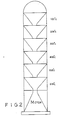
- This invention concerns a continuous molecular separating distillation column comprising a plurality of like unit sections in series in vertical alignment, wherein each unit section is internally provided with a rotor and a condensing means, all the rotors being rotatably mounted on a common shaft driven by a motor, each of said rotors having a circular reservoir, preferably with an arcuate bottom, and the wall of each said reservoir being provided with heating means, each of said condensing means being spaced apart from its respective rotor by a clearance in a manner such that the vaporized ingredient from said rotor can be condensed on the condensing means and discharged to the outside, and each of said unit sections is so structured that the unvaporized portion of the liquid coming from the unit section above, or from the feeding entrance, if this section is the uppermost section, can be removed by the centrifugal force of the rotor and discharged into the unit section below or to the outside, if the section is the bottommost section.
- a continuous molecular separating distillation column of this type is known from US-A-2585202.
- the efficiency of the known distillation column is not satisfying.
- the column of the above described type is characterized according to the present invention in that the rotor is W-shaped in cross section and by a reflecting means which is located on the underside of said rotor to reflect the downward radiation from said rotor.
- the reflecting means not only gives back the radiation of heat to the flowing fluid film but also reduces the heat loss of the heating means from the underside by convection, so that the efficiency of the whole distillation column is enhanced.
- each section of the column has a funnel-shaped interior, namely gutter 7, which is centrally passed through by a rotary shaft 1.
- gutter 7 there is further provided a rotor 6 mounted on shaft 1 through a bearing 2 for high speed rotation, which rotor 6 with its W-shaped profile has an arcuate inside bottom and is externally provided with heater 3 for heating the fluid flowing therethrough.
- condensing means 4 arranged in the form of a circular V-shaped chute and a collector 5 is provided at the bottom of said condensing means (4) to collect the distillate fraction, which then is pumped out for use.
- Mixture is fractioned in each section of the column at different temperatures.
- the boiling temperature is increased by 100°C from one section to the next adjacent one, for example, top section B.P. 100°C next section, B.P. 200°C ... and so forth.
- the driving motor can be installed at the bottom of the whole column, or alternatively, at the top to drive all the rotors at the same time.
- the mixture is fed from the entrance 8 at the top section of the column.
- the fluid flows along shaft 1 to rotor 6 which is rotating at high speed and is heated by its heater (3) so that the fluid reaching preset boiling point (for example 100°C) is evaporated at once and the vapor is then condensed upon contact with the condensing means (4).
- preset boiling point for example 100°C
- the condensate in turn flows along the condensing means (4) and is collected by collector (5). Since the clearance between condensing means 4 and rotor 6 is optimally designed by experiments and the flow is spread into a thin film due to the high speed spinning of rotor 6, the fluid is immediately evaporated leaving little residue which should be evaporated. No unfavorable physical changes can occur during the evaporation.
- the less volatile fluid portion, of which the boiling range is above the preset valve of this section, successfully travels through the whole radius of rotor 6 without being evaporated and is shaken away by centrifugal force to strike at the wall of the gutter (7) along which it flows downward to the next unit section and is subject to like procedure.
- heater 3 is further externally enclosed by a reflecting foil 72 which not only gives back the radiation of heat to the flowing fluid film but also reduce the heat loss of the heaters from underside by convection.
- a flange 721 is provided to keep the unevaporated portion from flowing into the interspace between radiating foil 72 and heater 3.
- the fluid when flowing to the next unit section through its inlet port 8, is susceptible to be splashed by the quickly spinning rotor 6 if directly contact with the latter at a high level without passing a slope acting as bumper. For this reason there is further provided means lying parallel to the inner conical surface of rotor 6, which means provide, a guide for the liquid.
- This invention has several advantages over the yet known distillating means. Firstly, the heater and the enlarged area of heat transfer as a result of the formation of the thin film, largely enhance the efficiency of both evaporation and condensation.
- the multi-sectional column enables several evaporations and condensations to be carried out in a single flow path because the temperature of the fluid after leaving the top section has risen considerably high and only needs some further heating to reach the boiling range of the second section.
- the temperature of the fluid after leaving the first column where the preset boiling point is 100°C may slightly drop to 90°C which however, can be raised to 200°C almost twice as faster as starting from normal temperature 25°C to 200°C, thus saving both the time and the power consumption.
Landscapes
- Chemical & Material Sciences (AREA)
- Chemical Kinetics & Catalysis (AREA)
- Vaporization, Distillation, Condensation, Sublimation, And Cold Traps (AREA)
- Organic Low-Molecular-Weight Compounds And Preparation Thereof (AREA)
Claims (2)
Priority Applications (3)
| Application Number | Priority Date | Filing Date | Title |
|---|---|---|---|
| DE8181109316T DE3173475D1 (en) | 1981-10-30 | 1981-10-30 | Continuous molecular separating distillation column |
| AT81109316T ATE17324T1 (de) | 1981-10-30 | 1981-10-30 | Kolonne zur kontinuierlichen molekulardestillation. |
| EP81109316A EP0078332B1 (de) | 1981-10-30 | 1981-10-30 | Kolonne zur kontinuierlichen Molekulardestillation |
Applications Claiming Priority (1)
| Application Number | Priority Date | Filing Date | Title |
|---|---|---|---|
| EP81109316A EP0078332B1 (de) | 1981-10-30 | 1981-10-30 | Kolonne zur kontinuierlichen Molekulardestillation |
Publications (2)
| Publication Number | Publication Date |
|---|---|
| EP0078332A1 EP0078332A1 (de) | 1983-05-11 |
| EP0078332B1 true EP0078332B1 (de) | 1986-01-08 |
Family
ID=8187985
Family Applications (1)
| Application Number | Title | Priority Date | Filing Date |
|---|---|---|---|
| EP81109316A Expired EP0078332B1 (de) | 1981-10-30 | 1981-10-30 | Kolonne zur kontinuierlichen Molekulardestillation |
Country Status (3)
| Country | Link |
|---|---|
| EP (1) | EP0078332B1 (de) |
| AT (1) | ATE17324T1 (de) |
| DE (1) | DE3173475D1 (de) |
Families Citing this family (4)
| Publication number | Priority date | Publication date | Assignee | Title |
|---|---|---|---|---|
| JPS60143802A (ja) * | 1983-08-18 | 1985-07-30 | クウチヤンダブリユ−,エス,リヤウ | 連続式分子蒸留塔 |
| KR102660991B1 (ko) * | 2019-11-05 | 2024-04-25 | 한화솔루션 주식회사 | 증류장치 |
| KR102577190B1 (ko) * | 2019-11-05 | 2023-09-11 | 한화솔루션 주식회사 | 증류장치 |
| CN112807727B (zh) * | 2021-03-01 | 2022-08-30 | 开封博凯生物化工有限公司 | 一种化工制药用的蒸馏设备 |
Family Cites Families (6)
| Publication number | Priority date | Publication date | Assignee | Title |
|---|---|---|---|---|
| US2210926A (en) * | 1936-07-06 | 1940-08-13 | Distillation Products Inc | Vacuum distillation process |
| US2218342A (en) * | 1938-04-06 | 1940-10-15 | Chemical Foundation Inc | Distillation column |
| US2585202A (en) * | 1948-05-24 | 1952-02-12 | Phillips Petroleum Co | Molecular still |
| US2562153A (en) * | 1948-08-31 | 1951-07-24 | Thomas I Taylor | Vacuum distillation |
| US2694675A (en) * | 1951-08-21 | 1954-11-16 | Walter H Hogan | Multistage centrifugal rectification apparatus |
| BE649513A (de) * | 1963-06-21 |
-
1981
- 1981-10-30 DE DE8181109316T patent/DE3173475D1/de not_active Expired
- 1981-10-30 EP EP81109316A patent/EP0078332B1/de not_active Expired
- 1981-10-30 AT AT81109316T patent/ATE17324T1/de not_active IP Right Cessation
Also Published As
| Publication number | Publication date |
|---|---|
| DE3173475D1 (en) | 1986-02-20 |
| ATE17324T1 (de) | 1986-01-15 |
| EP0078332A1 (de) | 1983-05-11 |
Similar Documents
| Publication | Publication Date | Title |
|---|---|---|
| US3423294A (en) | Vortex flow film distillation process | |
| US7112262B2 (en) | Device for downward flow evaporation of a liquid substance and subsequent condensation of the vapour formed | |
| FI66294B (fi) | Destillationsanordning som arbetar enligt termokompressorprincipen | |
| GB2134803A (en) | Centrifugal thin film evaporator | |
| US3640330A (en) | Heat exchangers | |
| US4230529A (en) | Distillation apparatus | |
| US3457982A (en) | Evaporation and distillation apparatus | |
| US2606146A (en) | High-vacuum multistage distillation method and apparatus | |
| EP0078332B1 (de) | Kolonne zur kontinuierlichen Molekulardestillation | |
| US3020211A (en) | Film-forming and wiping distillation process and apparatus for carrying out the same | |
| US2218240A (en) | Vacuum distillation | |
| US3012416A (en) | Evaporative cooling apparatus | |
| JPS6049002B2 (ja) | 薄膜蒸発器 | |
| US2562153A (en) | Vacuum distillation | |
| US2609335A (en) | Fractional distillation process and apparatus | |
| US2427718A (en) | Vacuum distillation with circulation of gas | |
| US2370464A (en) | Vacuum distillation apparatus | |
| US4065346A (en) | Roter thin-film evaporator | |
| US5036908A (en) | High inlet artery for thermosyphons | |
| US3489651A (en) | Distillation apparatus utilizing frictional heating and compression of vapors | |
| US2585202A (en) | Molecular still | |
| FI61999B (fi) | Destillationsanordning som arbetar enligt termokompressorprincipen | |
| US9327207B2 (en) | Spherical desalination device | |
| CN119056093B (zh) | 一种烯烃分离纯化装置 | |
| US3141807A (en) | Vacuum evaporator |
Legal Events
| Date | Code | Title | Description |
|---|---|---|---|
| PUAI | Public reference made under article 153(3) epc to a published international application that has entered the european phase |
Free format text: ORIGINAL CODE: 0009012 |
|
| AK | Designated contracting states |
Designated state(s): AT BE CH DE FR GB IT LI LU NL SE |
|
| 17P | Request for examination filed |
Effective date: 19830507 |
|
| GRAA | (expected) grant |
Free format text: ORIGINAL CODE: 0009210 |
|
| AK | Designated contracting states |
Designated state(s): AT BE CH DE FR GB IT LI LU NL SE |
|
| REF | Corresponds to: |
Ref document number: 17324 Country of ref document: AT Date of ref document: 19860115 Kind code of ref document: T |
|
| REF | Corresponds to: |
Ref document number: 3173475 Country of ref document: DE Date of ref document: 19860220 |
|
| ITF | It: translation for a ep patent filed | ||
| ET | Fr: translation filed | ||
| PG25 | Lapsed in a contracting state [announced via postgrant information from national office to epo] |
Ref country code: LU Free format text: LAPSE BECAUSE OF NON-PAYMENT OF DUE FEES Effective date: 19861031 |
|
| PLBE | No opposition filed within time limit |
Free format text: ORIGINAL CODE: 0009261 |
|
| STAA | Information on the status of an ep patent application or granted ep patent |
Free format text: STATUS: NO OPPOSITION FILED WITHIN TIME LIMIT |
|
| 26N | No opposition filed | ||
| PGFP | Annual fee paid to national office [announced via postgrant information from national office to epo] |
Ref country code: LU Payment date: 19901017 Year of fee payment: 10 |
|
| PGFP | Annual fee paid to national office [announced via postgrant information from national office to epo] |
Ref country code: CH Payment date: 19901018 Year of fee payment: 10 |
|
| EPTA | Lu: last paid annual fee | ||
| ITTA | It: last paid annual fee | ||
| PG25 | Lapsed in a contracting state [announced via postgrant information from national office to epo] |
Ref country code: LI Effective date: 19911031 Ref country code: CH Effective date: 19911031 |
|
| PGFP | Annual fee paid to national office [announced via postgrant information from national office to epo] |
Ref country code: NL Payment date: 19911031 Year of fee payment: 11 Ref country code: AT Payment date: 19911031 Year of fee payment: 11 |
|
| PGFP | Annual fee paid to national office [announced via postgrant information from national office to epo] |
Ref country code: BE Payment date: 19911113 Year of fee payment: 11 |
|
| REG | Reference to a national code |
Ref country code: CH Ref legal event code: PL |
|
| PG25 | Lapsed in a contracting state [announced via postgrant information from national office to epo] |
Ref country code: AT Effective date: 19921030 |
|
| PG25 | Lapsed in a contracting state [announced via postgrant information from national office to epo] |
Ref country code: BE Effective date: 19921031 |
|
| BERE | Be: lapsed |
Owner name: LAIO KOU TOUNG Effective date: 19921031 |
|
| PG25 | Lapsed in a contracting state [announced via postgrant information from national office to epo] |
Ref country code: NL Effective date: 19930501 |
|
| NLV4 | Nl: lapsed or anulled due to non-payment of the annual fee | ||
| PGFP | Annual fee paid to national office [announced via postgrant information from national office to epo] |
Ref country code: FR Payment date: 19931015 Year of fee payment: 13 |
|
| PGFP | Annual fee paid to national office [announced via postgrant information from national office to epo] |
Ref country code: DE Payment date: 19931018 Year of fee payment: 13 |
|
| PGFP | Annual fee paid to national office [announced via postgrant information from national office to epo] |
Ref country code: GB Payment date: 19931020 Year of fee payment: 13 |
|
| PGFP | Annual fee paid to national office [announced via postgrant information from national office to epo] |
Ref country code: SE Payment date: 19931021 Year of fee payment: 13 |
|
| PG25 | Lapsed in a contracting state [announced via postgrant information from national office to epo] |
Ref country code: GB Effective date: 19941030 |
|
| PG25 | Lapsed in a contracting state [announced via postgrant information from national office to epo] |
Ref country code: SE Effective date: 19941031 |
|
| EAL | Se: european patent in force in sweden |
Ref document number: 81109316.0 |
|
| GBPC | Gb: european patent ceased through non-payment of renewal fee |
Effective date: 19941030 |
|
| PG25 | Lapsed in a contracting state [announced via postgrant information from national office to epo] |
Ref country code: FR Effective date: 19950630 |
|
| PG25 | Lapsed in a contracting state [announced via postgrant information from national office to epo] |
Ref country code: DE Effective date: 19950701 |
|
| EUG | Se: european patent has lapsed |
Ref document number: 81109316.0 |
|
| REG | Reference to a national code |
Ref country code: FR Ref legal event code: ST |