EP0077954B1 - Missile - Google Patents
Missile Download PDFInfo
- Publication number
- EP0077954B1 EP0077954B1 EP82109324A EP82109324A EP0077954B1 EP 0077954 B1 EP0077954 B1 EP 0077954B1 EP 82109324 A EP82109324 A EP 82109324A EP 82109324 A EP82109324 A EP 82109324A EP 0077954 B1 EP0077954 B1 EP 0077954B1
- Authority
- EP
- European Patent Office
- Prior art keywords
- projectile
- segments
- fact
- accordance
- missile
- Prior art date
- Legal status (The legal status is an assumption and is not a legal conclusion. Google has not performed a legal analysis and makes no representation as to the accuracy of the status listed.)
- Expired
Links
Images


Classifications
-
- F—MECHANICAL ENGINEERING; LIGHTING; HEATING; WEAPONS; BLASTING
- F42—AMMUNITION; BLASTING
- F42B—EXPLOSIVE CHARGES, e.g. FOR BLASTING, FIREWORKS, AMMUNITION
- F42B12/00—Projectiles, missiles or mines characterised by the warhead, the intended effect, or the material
- F42B12/02—Projectiles, missiles or mines characterised by the warhead, the intended effect, or the material characterised by the warhead or the intended effect
- F42B12/36—Projectiles, missiles or mines characterised by the warhead, the intended effect, or the material characterised by the warhead or the intended effect for dispensing materials; for producing chemical or physical reaction; for signalling ; for transmitting information
- F42B12/56—Projectiles, missiles or mines characterised by the warhead, the intended effect, or the material characterised by the warhead or the intended effect for dispensing materials; for producing chemical or physical reaction; for signalling ; for transmitting information for dispensing discrete solid bodies
- F42B12/58—Cluster or cargo ammunition, i.e. projectiles containing one or more submissiles
- F42B12/60—Cluster or cargo ammunition, i.e. projectiles containing one or more submissiles the submissiles being ejected radially
Definitions
- the invention relates to a missile for transporting a plurality of payloads to be launched at a predetermined point in the trajectory with the features of the preamble of claim 1.
- Such a missile is described in DE-A-29 20 347.
- the design according to this OS does not have any segments lying against one another with their side walls, which could form the supporting outer jacket of the projectile and which could withstand the considerable acceleration values both in the longitudinal direction and in the circumferential direction when the missile was launched and flown.
- there is a supporting frame consisting of an inner frame and attached jacket sections. In between, outlet openings are formed which are covered by thin metal sheets which rest on the walls with a frictional connection.
- This is a very complex and cumbersome construction, especially since ejection bellows, which are pneumatically operated, are required to push the sheets out.
- a missile with a supporting outer jacket without support internals is formed solely by segment-shaped outer wall parts.
- US-A-3 088 404 discloses a missile with ejectable payloads, which consists of a one-piece metallic cylindrical shell. On its inner wall, segment-shaped holding plates are arranged transversely to the longitudinal direction of the casing, which are connected to one another by means of a tongue and groove connection with the aid of rivet bolts. To repel the payloads, the rivet bolts and the casing should be disassembled by explosion in a manner not described in detail. No reference to the present invention can be inferred from this either.
- the object of the invention is to improve a missile of the type mentioned in such a way that a shell of low weight is formed from segments without internal support internals which can withstand the considerable acceleration values occurring in the longitudinal axis direction and in the circumferential direction when the missile is moving, and yet with its own Spring force that can only be easily thrown off at the same time by interlocking segments.
- FIG. 1 shows a schematic representation of a missile for transporting a plurality of payloads ejected at a predeterminable point of the flight path.
- the tail unit 2 arranged at the rear of the missile there is an essentially hollow-cylindrical part of the missile 10, which is delimited on the outside by a tubular casing 12.
- This envelope 12 encloses a payload space 4, in which payloads 11 are arranged separately, if necessary, by floors 24 extending transversely to the longitudinal axis of the missile 10.
- these payloads 11 In order to be able to cover the widest possible terrain strip along the trajectory of the missile with payloads 11 to be ejected, these payloads 11 must be ejected in the radial direction, that is, perpendicular to the direction of travel of the missile 10. For this purpose, it is necessary that at a predeterminable point in time, namely when the missile 10 has reached a specific point on its trajectory, the tubular envelope surrounding the payload space 4 is removed in order to enable the payloads to be ejected in the radial direction.
- the invention is particularly concerned with the configuration of the tubular shell 12 of the missile, which has to withstand considerable acceleration values both in the longitudinal axis direction of the missile 10 and in the circumferential direction when the missile 10 is launched and moved.
- the cover 12 must nevertheless be easily ejectable in order to enable the unimpeded ejection of the payloads 11.
- FIG. 2 shows a partial sectional illustration in the longitudinal axis direction of the missile 10 in the region of the payload space of the missile 10.
- FIG. 3 shows a view of a cross-sectional plane of the missile 10 as viewed from line 3 - 3 according to FIG. Fig. 2.
- FIG. 4 shows a detailed illustration from FIG. 3 on a substantially enlarged scale.
- the tubular casing 12 consists of a plurality of segments 13, 13 'which are detachably connected to one another and which abut one another with their side edges 16, 16' in such a way that they essentially form a cylinder jacket surface.
- the segments 13, 13 ' are expediently made of an elastic material, so that their bending on a cylindrical surface causes a resetting force.
- the segments 13, 13 ' can therefore only be forced into the cylinder shape using a prestress and can be braced in this position.
- FIG. 5 shows a partial sectional view in the longitudinal axis direction of the missile 10 in the region of such a rod 18.
- the rod 18 has eccentric and / or conical or stepped seats 19 in the region of the hook-shaped extensions 15, 15 ', to which the hook-shaped extensions 15, 15 'can create, whereby they can be clamped against each other when the rod 18 moves relative to the hook-shaped extensions 15, 15'.
- this bracing is achieved by moving the rod 18 during the assembly of the segments 13, 13 'in the longitudinal axis direction of the missile 10.
- the hook-shaped extensions 15, 15 ' can be braced by rotating the rod 18 about its longitudinal axis and / or simultaneous longitudinal movement of the rod 18 in the longitudinal axis direction of the missile 10.
- the locking of the segments 13, 13 'achieved with the aid of the rod 18 can be canceled in a simple manner after the predetermined ejection point of the payloads 11 has been reached by the rod 18 being moved and / or rotated in the opposite direction, as in the case of assembly.
- This longitudinal or rotational movement of the rod 18 naturally requires a certain force.
- This can be provided in a particularly simple and reliable manner by means of a pyrotechnic charge 20 provided with an optionally electrically activatable igniter 21.
- the rod 18 is expediently designed as a hollow cylinder which is closed on one side and rests with its open end piece 22 on the pyrotechnic charge 20.
- the gases generated when the pyrotechnic charge 20 is ignited can consequently penetrate through the open end piece 22 of the rod 18 into its interior and exert a force on its end face opposite the open end piece. Since the pyrotechnic charge 20 also acts on the circular surface of the rod 18 with which it rests on the pyrotechnic charge 20, a pressure-tensile force on the rod 18 results in a particularly advantageous manner, which moves it in the longitudinal axis direction of the missile and thereby unlocking the segments 13, 13 'leads.
- floors 24 are provided which extend transversely to the longitudinal axis of the missile 10, on the lateral surface 25 of which the segments 13, 13 'rest with their inner surface.
- grooves 26 are embedded in the lateral surfaces 25 of the bottoms, into which a collar 27 arranged on the segments 13, 13' engages.
- grooves 26 and collar 27 are preferably wedge-shaped in cross section (FIG. 6).
- the missile At launch, the missile is given a rotational movement about its longitudinal axis, which can also be maintained or reinforced during flight, if necessary, by additionally arranged engines.
- This rotational movement leads to force components directed transversely to the longitudinal axis, which act on the segments 12, 13 'forming the shell 12 with the aim of torsion.
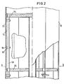
- the segments 13, 13' and the bottoms 24 are either hooked in the area of their wedge-shaped connection (FIG. 7) or equipped with interlocking teeth 28 (FIG. 8).
- Fig. 8 shows a sectional view along the line 8 - gem.
- the segments 13, 13 ' are preferably produced from light metals commonly used in aircraft construction or also from plastic, in particular fiber-reinforced plastic.
- a support structure extending in the longitudinal axis direction of the missile is advantageously provided, which on the one hand divides the payload space 4 into individual compartments 4 'for receiving a payload 11 each and which on the other hand offers support points or support surfaces 29 to which the segments 13, 13 'can also support with their inner surface 14.
- the support structure expediently comprises partition walls 30 which are arranged parallel to the longitudinal axis of the missile and which enclose an angle between them and which partition off the rods 18, the hook-shaped extensions 15, 15 'and the joints between the segments 13, 13' in relation to the payloads 11 .
- the segments 13, 13 'simultaneously serve to hold additional or correction engines, which, for example during the flight phase of the missile 10, maintain or reinforce the swirl communicated to it during takeoff. These additional or correction engines are then separated from the missile together with the segments 13, 13 'when unlocked.
- the unlocking of the segments 13, 13 ' can be carried out simultaneously or with a time delay if necessary.
- the chronological order can be checked by activating the pyrotechnic charges 20.
- the ejection of the payloads 11 can either take place simultaneously with the separation of the segments 13, 13 'or take place with a time delay.
- the latter possibility allows the targeted ejection of a payload 11 in correlation to the rotational movement of the missile 10 with respect to its longitudinal axis. This proves to be particularly expedient in those cases in which a large radial throw range is aimed at when the payloads 11 are ejected.
Description
Die Erfindung betrifft einen Flugkörper zum Transport einer Mehrzahl von an einem vorbestimmten Punkt der Flugbahn auszustoßenden Nutzlasten mit den Merkmalen des Oberbegriffs des Anspruchs 1.The invention relates to a missile for transporting a plurality of payloads to be launched at a predetermined point in the trajectory with the features of the preamble of claim 1.
Ein derartiger Flugkörper ist in der DE-A-29 20 347 beschrieben. Die Konstruktion nach dieser OS weist keine mit ihren Seitenwänden aneinanderliegende Segmente auf die den tragenden Außenmantel des Geschosses bilden könnten und die den erheblichen Beschleunigungswerten sowohl in Längsrichtung als auch in Umfangsrichtung beim Abschuß und Fliegen des Flugkörpers standhalten könnten. Dort ist vielmehr ein tragendes Gestell bestehend aus einem inneren Gerüst und daran befestigten Mantelabschnitten vorhanden. Dazwischen sind Austrittsöffnungen gebildet, die von dünnen Blechen abgedeckt sind die mit einer Reibschlußverbindung an den Wänden anliegen. Das ist eine sehr aufwendige und umständliche Konstruktion, zumal zum Herausdrücken der Bleche noch Ausstoßbälge, die pneumatisch betrieben werden erforderlich sind. Ein Hinweis darauf, einen Flugkörper mit tragendem Außenmantel ohne Stützeinbauten allein durch segmentförmige Außenwandteile zu bilden, ist daraus nicht zu entnehmen.Such a missile is described in DE-A-29 20 347. The design according to this OS does not have any segments lying against one another with their side walls, which could form the supporting outer jacket of the projectile and which could withstand the considerable acceleration values both in the longitudinal direction and in the circumferential direction when the missile was launched and flown. Rather, there is a supporting frame consisting of an inner frame and attached jacket sections. In between, outlet openings are formed which are covered by thin metal sheets which rest on the walls with a frictional connection. This is a very complex and cumbersome construction, especially since ejection bellows, which are pneumatically operated, are required to push the sheets out. There is no indication that a missile with a supporting outer jacket without support internals is formed solely by segment-shaped outer wall parts.
Die weiterhin bekannte US-A-3 088 404 offenbart einen Flugkörper mit ausstoßbaren Nutzlasten, der aus einer einteiligen metallischen zylindrischen Hülle besteht. An dessen Innenwand sind quer zur Längsrichtung der Hülle segmentförmige Halteplatten angeordnet, die nach einer Art Nut- und Federverbindung mit Hilfe von Nietbolzen miteinander verbunden sind. Zum Abstoßen der Nutzlasten sollen die Nietbolzen sowie die Hülle auf nicht näher beschriebene Weise durch Explosion zerlegt werden. Auch daraus ist kein Hinweis auf die vorliegende Erfindung zu entnehmen.The further known US-A-3 088 404 discloses a missile with ejectable payloads, which consists of a one-piece metallic cylindrical shell. On its inner wall, segment-shaped holding plates are arranged transversely to the longitudinal direction of the casing, which are connected to one another by means of a tongue and groove connection with the aid of rivet bolts. To repel the payloads, the rivet bolts and the casing should be disassembled by explosion in a manner not described in detail. No reference to the present invention can be inferred from this either.
Aufgabe der Erfindung ist es, einen Flugkörper der eingangs genannten Art derart zu verbessern daß eine Hülle von geringen Eigengewicht aus Segmenten ohne innere Stützeinbauten gebildet ist die den bei Fortbewegung des Flugkörpers auftretenden erheblichen Beschleunigungswerten in Längsachsenrichtung und in Umfangsrichtung standhalten kann und bei der trotzdem durch eigene Federkraft, die nur miteinander verriegelten Segmente zugleich leicht abwerfbar sind.The object of the invention is to improve a missile of the type mentioned in such a way that a shell of low weight is formed from segments without internal support internals which can withstand the considerable acceleration values occurring in the longitudinal axis direction and in the circumferential direction when the missile is moving, and yet with its own Spring force that can only be easily thrown off at the same time by interlocking segments.
Die zur Lösung der gestellten Aufgabe notwendigen wesentlichen Merkmale der Erfindung sind im Patentanspruch 1 genannt.The essential features of the invention necessary to achieve the object are mentioned in claim 1.
Vorteilhafte Ausgestaltungen und Weiterbildungen der Erfindung gehen aus den Unteransprüchen hervor.Advantageous refinements and developments of the invention emerge from the subclaims.
Die Erfindung wird nachfolgend unter Bezug auf die Zeichnung näher erläutert. Dabei zeigt:
- Fig. 1: eine schematische Darstellung eines Flugkörpers mit einer z. T. geschnittenen, rohrförmigen Hülle, die den Blick auf die Nutzlast freigibt;
- Fig. 2: eine Schnittdarstellung des Flugkörpers im Bereich des Nutzlastraums;
- Fig. 3: eine Sicht auf eine Querschnittsfläche des Flugkörpers mit Blickrichtung von Linie 3-3 gem. Fig. 2;
- Fig. 4: eine vergrößerte Detaildarstellung der Zeichnung gemäß Fig. 3;
- Fig. 5: eine Schnittdarstellung in Längsachsenrichtung des Flugkörpers entlang Linie 5 - 5 gemäß Fig. 4;
- Fig. 6: eine vergrößerte Schnittdarstellung der Befestigung der Segmente an einem den Flugkörper quer zur Längsachse unterteilenden Boden;
- Fig. 7: eine Schnittdarstellung eines weiteren Ausführungsbeispiels zur Befestigung der Segmente;
- Fig. 8: eine Schnittdarstellung entlang Linie 8 - 8 gem. Fig. 7.
- 1: a schematic representation of a missile with a z. T. cut, tubular shell that reveals the payload;
- 2 shows a sectional illustration of the missile in the region of the payload space;
- 3: a view of a cross-sectional area of the missile with line of sight from line 3-3 acc. Fig. 2;
- FIG. 4: an enlarged detailed illustration of the drawing according to FIG. 3;
- 5 shows a sectional illustration in the longitudinal axis direction of the missile along line 5 - 5 according to FIG. 4;
- 6 shows an enlarged sectional illustration of the fastening of the segments on a floor dividing the missile transversely to the longitudinal axis;
- 7 shows a sectional illustration of a further exemplary embodiment for fastening the segments;
- 8 shows a sectional view along line 8-8 according to FIG. Fig. 7.
Fig. 1 zeigt eine schematische Darstellung eines Flugkörpers zum Transport einer Mehrzahl von an einem vorbestimmbaren Punkt der Flugbahn ausgestoßenen Nutzlasten. Zwischen der Ogive 1 und dem am Heck des Flugkörpers angeordneten Leitwerk 2 ist ein im wesentlichen hohlzylinderförmig ausgebildeter Teil des Flugkörpers 10 angeordnet, der nach außen von einer rohrförmigen Hülle 12 begrenzt ist. Diese Hülle 12 umschließt einen Nutzlastraum 4, in dem ggf. durch sich quer zur Längsachse des Flugkörpers 10 erstreckende Böden 24 getrennt Nutzlasten 11 angeordnet sind. Um einen möglichst breiten Geländestreifen entlang der Flugbahn des Flugkörpers mit auszustoßenden Nutzlasten 11 belegen zu können, müssen diese Nutzlasten 11 in Radialrichtung, also senkrecht zur Fortbewegungsrichtung des Flugkörpers 10 ausgestoßen werden. Dazu ist es erforderlich, daß zu einem vorbestimmbaren Zeitpunkt, nämlich dann, wenn der Flugkörper 10 einen bestimmten Punkt seiner Bahnkurve erreicht hat, die den Nutzlastraum 4 umgebende rohrförmige Hülle entfernt wird, um den Ausstoß der Nutzlasten in Radialrichtung zu ermöglichen.1 shows a schematic representation of a missile for transporting a plurality of payloads ejected at a predeterminable point of the flight path. Between the ogive 1 and the
Die Erfindung befaßt sich insbesondere mit der Ausgestaltung der rohrförmigen Hülle 12 des Flugkörpers, die bei Start und Fortbewegung des Flugkörpers 10 erheblichen Beschleunigungswerten sowohl in Längsachsenrichtung des Flugkörpers 10, als auch in Umfangsrichtung standzuhalten hat. Die Hülle 12 muß dennoch leichtabwerfbar sein, um den ungehinderten Ausstoß der Nutzlasten 11 zu ermöglichen.The invention is particularly concerned with the configuration of the
Weiter muß ihr Eigengewicht möglichst gering sein, um den Totlastanteil des Flugkörpers weitgehend zu reduzieren.Furthermore, their own weight must be as low as possible in order to largely reduce the dead load component of the missile.
Die Erfindung bietet insbesondere folgende Vorteile:
- - Die gesamte Außenhülle des Flugkörperabschnitts,aus dem die
Nutzlast 11 seitlich herausgeschleudert werden soll, kann simultan lediglich aufgrund eigener Federspannung abgeschleudert werden; - - die gesamte Außenhülle übernimmt den wesentlichen Teil der beim Abschuß und ggf. bei Abbremsen des Flugkörpers auf der Flugbahn auftretenden Massenlängskräfte der Nutzlast;
- - die gesamte Hülle übernimmt den wesentlichen Teil der bei Drehbeschleunigungen während des Abschusses und auf der Flugbahn auftretenden Drehmomente der Nutzlast und ihrer Befestigungsteile;
- - die Hülle muß weder vernietet, geschweißt oder verschraubt werden, sondern wird lediglich über beispielsweise Exzenter verriegelt und in Rillungen bzw. Verzahnungen gehalten;
- - die Hülle kann mit beliebig vielen, im wesentlichen senkrecht zur Flugkörperlängsachse liegenden Zwischenböden für die Befestigung von Nutzlastbaugruppen verbunden werden.
- - The entire outer shell of the missile section, from which the
payload 11 is to be thrown out laterally, can only be thrown off simultaneously due to its own spring tension; - - The entire outer shell takes over the major part of the mass longitudinal forces of the payload occurring during the launch and possibly braking of the missile on the trajectory;
- - The entire shell takes over the essential part of the torques of the payload and its fastening parts occurring during rotational accelerations during the launch and on the trajectory;
- - The shell does not have to be riveted, welded or screwed, but is only locked by means of eccentrics, for example, and held in grooves or gears;
- - The casing can be connected to any number of intermediate floors, which are essentially perpendicular to the longitudinal axis of the missile, for fastening payload assemblies.
Fig. 2 zeigt eine teilweise Schnittdarstellung in Längsachsenrichtung des Flugkörpers 10 im Bereich des Nutzlastraums des Flugkörpers 10.2 shows a partial sectional illustration in the longitudinal axis direction of the
Fig. 3 zeigt eine Ansicht auf eine Querschnittsebene des Flugkörpers 10 mit Blickrichtung aus Linie 3 - 3 gem. Fig. 2.FIG. 3 shows a view of a cross-sectional plane of the
Fig. 4 zeigt eine Detaildarstellung aus Fig. 3 in wesentlich vergrößertem Maßstab.FIG. 4 shows a detailed illustration from FIG. 3 on a substantially enlarged scale.
Die rohrförmige Hülle 12 besteht aus einer Mehrzahl lösbar miteinander verbundener Segmente 13, 13', die mit ihren Seitenkanten 16, 16' derart aufeinanderstoßen, daß sie im wesentlichen eine Zylindermantelfläche bilden. Zweckmäßig bestehen die Segmente 13, 13' aus einem elastischen Material, so daß ihre Biegung auf eine Zylindermantelfläche eine Rückstelikraft hervorruft. Die Segmente 13, 13' können daher nur unter Anwendung einer Vorspannung in die Zylindergestalt gezwungen und in dieser Lage verspannt werden. Dies hat das vorteilhafte Ergebnis, daß nach Lösung der Verspannung kurz vor Freigabe der Nutzlast 11 die Segmente 13, 13' sich in ihre ursprüngliche Gestalt umformen und sich so auf diese Weise im wesentlichen selbsttätig vom Flugkörper ablösen und Austrittsöffnungen für das Ausstoßen der Nutzlasten 11 freigeben. Um eine Verspannung der die Hülle 12 des Flugkörpers 10 bildenden Segmente 13, 13' zu erzielen, sind jeder Seitenkante 16, 16' jedes Segments 13,13' benachbart auf der Innenfläche 14 jedes Segments ins Innere des Flugkörpers 10 ragende hakenförmige Fortsätze 15, 15' angeordnet. Diese überragen die jeweilige Seitenkante 16, 16' des ihnen zugeordneten Segments 13, 13' in Richtung auf das benachbarte Segment 13 bzw. 13, und sind bei den mit den Seitenkanten 16, 16' aneinanderstoßenden Segmenten 13, 13' derart in der Höhe versetzt angeordnet, daß sie paarweise übereinandergreifend zangenförmig eine Ausnehmung 17 umschließen. Dabei sind die von den Fortsätzen 15, 15' benachbarter Segmente 13, 13' umschlossenen Ausnehmungen 17 miteinander fluchtend angeordnet. Durch diese Ausnehmungen 17 greift, wie insbesondere aus Fig. 2 und Fig. 5 ersichtlich ist, ein Stab 18 hindurch, der parallel zur Längsachse des Flugkörpers 10 angeordnet ist. Dabei ist für jede Stoßstelle aneinandergrenzender Segmente 13, 13' ein derartiger Stab 18 vorgesehen.The
Fig. 5 zeigt eine Teilschnittdarstellung in Längsachsenrichtung des Flugkörpers 10 im Bereich eines derartigen Stabs 18. ler Stab 18 weist im Bereich der hakenförmigen Fortsätze 15, 15' exzentrisch und/oder konisch oder abgestuft ausgebildete Sitze 19 auf, an die sich die hakenförmigenFortsätze 15, 15' anlegen können, wodurch sie bei Relativbewegung des Stabs 18 in bezug auf die hakenförmigen Fortsätze 15, 15' gegeneinander verspannbar sind. Bei konusförmig und/oder abgestuft ausgebildeten Sitzen 19 wird diese Verspannung dabei durch eine Bewegung des Stabs 18 bei der Montage der Segmente 13, 13' in Längsachsenrichtung des Flugkörpers 10 erzielt. Bei exzentrischer und/oder konusförmiger Ausbildung der Sitze 19 läßt sich eine Verspannung der hakenförmigen Fortsätze 15, 15' durch eine Drehbewegung des Stabs 18 um seine Längsachse und/oder eine gleichzeitige Longitudinalbewegung des Stabs 18 in Längsachsenrichtung des Flugkörpers 10 erzielen. Die mit Hilfe des Stabs 18 erzielte Verriegelung der Segmente 13, 13' kann nach Erreichen des vorbestimmten Ausstoßpunkts der Nutzlasten 11 auf einfache Weise dadurch aufgehoben werden, daß der Stab 18 in entgegengesetzter Richtung - wie bei der Montagebewegt und/oder gedreht wird. Diese Longitudinal- bzw. Drehbewegung des Stabs 18 setzt selbstverständlich eine gewisse Kraft voraus. Diese kann auf besonders einfache und betriebssichere Art und Weise durch eine mit einem ggf. elektrisch aktivierbaren Zünder 21 versehene pyrotechnische Ladung 20 bereitgestellt werden. Zweckmäßig wird dabei der Stab 18 als einseitig geschlossener Hohlzylinder ausgebildet, der mit seinem offenen Endstück 22 auf der pyrotechnischen Ladung 20 aufliegt. Die bei Zündung der pyrotechnischen Ladung 20 erzeugten Gase können demzufolge durch das offene Endstück 22 des Stabs 18 in dessen Innenraum eindringen und auf seine dem offenen Endstück gegenüberliegende Stirnfläche eine Kraft ausüben. Da die pyrotechnische Ladung 20 gleichzeitig auch auf die Kreisringfläche des Stabs 18 einwirkt, mit dem dieser auf der pyrotechnischen Ladung 20 aufliegt, ergibt sich in besonders vorteilhafter Weise eine Druck-ZugKraft auf den Stab 18, die diesen in Längsachsenrichtung des Flugkörpers bewegt und dabei zu einer Entriegelung der Segmente 13, 13' führt. Die Verriegelung wird dadurch aufgehoben, daß die Sitze 19 des Stabs 18 bei der durch die pyrotechnische Ladung 20 bewirkten Fortbewegung des Stabs 18 aus dem Bereich der hakenförmigen Fortsätze 15, 15' hinausgleiten. Um dabei eine sichere Führung des Stabs 18 zu gewährleisten, werden zweckmäßig zusätzliche Führungen 23, 23' vorgesehen, die beispielsweise in den Nutzlastraum 4 unterteilenden Zwischenböden 24 angeordnet sind.5 shows a partial sectional view in the longitudinal axis direction of the
Für den Fall, daß die Verriegelung der hakenförmigen Fortsätze 15, 15' durch exzentrische Sitze 19 erfolgt, muß bei der Entriegelung eine Drehbewegung des Stabs 18 herbeigeführt werden. Diese Drehbewegung kann auf einfache Weise dadurch erzielt werden, daß zwischen Führung 23, 23' einerseits und Stab 18 andererseits ein Gewinde großer Steigung angeordnet ist. Die durch die pyrotechnische Ladung 20 erzeugte Kraft in Längsachsenrichtung des Stabs 18 wird dadurch in eine Drehbewegung umgewandelt.In the event that the hook-shaped
Wie insbesondere aus Fig. 2, Fig. 5, Fig. 6 und Fig. 7 hervorgeht, sind zur Begrenzung und/oder Abschottung des Nutzlastraums 4 quer zur Längsachse des Flugkörpers 10 sich erstreckende Böden 24 vorgesehen, auf deren Mantelfläche 25 die Segmente 13, 13' mit ihrer Innenfläche aufliegen. Um bei Beschleunigungswirkung in Längsachsenrichtung des Flugkörpers 10 eine Verschiebung der Segmente 13, 13' in Längsrichtung zu verhindern, sind in die Mantelflächen 25 der Böden 24 Nuten 26 eingelassen, in die ein an den Segmenten 13,13' angeordneter Bund 27 eingreift. Um einerseits eine besonders gute Verriegelung, andererseits jedoch leichte Lösbarkeit der Segmente 13, 13' vom restlichen Flugkörper 10 zu erreichen, werden Nuten 26 und Bund 27 bevorzugt im Querschnitt keilförmig ausgebildet (Fig. 6). Dem Flugkörper wird beim Start eine Rotationsbewegung um seine Längsachse erteilt, die auch während des Flugs ggf. durch zusätzlich angeordnete Triebwerke aufrechterhalten bzw. verstärkt werden kann. Diese Rotationsbewegung führt zu quer zur Längsachse gerichteten Kraftkomponenten, die mit dem Ziel einer Torsion anden die Hülle 12 bildenden Segmenten 13, 13' angreifen.As can be seen in particular from FIGS. 2, 5, 6 and 7, to limit and / or partition the
Um eine Verschiebung der Segmente 13, 13' in Umfangsrichtung zu verhindern, werden die Segmente 13,13' und die Böden 24 im Bereich ihrer keilförmigen Verbindung entweder verhakt (Fig. 7) oder mit ineinandergreifenden Zähnen 28 ausgestattet (Fig. 8).In order to prevent a displacement of the
Fig. 8 zeigt eine Schnittdarstellung entlang der Linie 8 - gem. Fig. 7.Fig. 8 shows a sectional view along the line 8 - gem. Fig. 7.
Die Segmente 13, 13' werden vorzugsweise aus im Flugzeugbau gebräuchlichen Leichtmetallen oder auch aus Kunststoff, inbesondere faserverstärktem Kunststoff hergestellt.The
Im Innern des Flugkörpers 10 wird vorteilhaft eine sich in Längsachsenrichtung des Flugkörpers erstreckende Stützkonstruktion vorgesehen, die einerseits den Nutzlastraum 4 in einzelne Abteile 4' zur Aufnahme je einer Nutzlast 11 unterteilt und die andererseits Stützpunkte oder Stützflächen 29 bietet, an die sich die Segmente 13,13' mit ihrer Innenfläche 14 zusätzlich abstützen können. Zweckmäßig umfaßt die Stützkonstruktion parallel zur Längsachse des Flugkörpers angeordnete Trennwände 30, die einen Winkel zwischen sich einschließen und die die Stäbe 18, die hakenförmigen Fortsätze 15, 15' sowie die -Stoßstellen zwischen den Segmenten 13, 13' in bezug auf die Nutzlasten 11 abschotten.In the interior of the
In einem weiteren, nicht durch eine Zeichnung erläuterten Ausführungsbeispiel der Erfindung dienen die Segmente 13, 13' gleichzeitig zur Halterung von Zusatz- oder Korrekturtriebwerken, die beispielsweise während der Flugphase des Flugkörpers 10, die diesem beim Start mitgeteilten Drall aufrechterhalten oder verstärken. Diese Zusatz- oder Korrekturtriebwerke werden dann bei der Entriegelung zusammen mit den Segmenten 13, 13' vom Flugkörper abgetrennt.In a further exemplary embodiment of the invention, which is not explained by a drawing, the
Die Entriegelung der Segmente 13, 13' kann im Bedarfsfalle gleichzeitig oder zeitlich verzögert durchgeführt werden. Die zeitliche Reihenfolge ist durch die Aktivierung der pyrotechnischen Ladungen 20 kontrollierbar.The unlocking of the
Das Ausstoßen der Nutzlasten 11 kann entweder gleichzeitig mit dem Abtrennen der Segmente 13, 13' erfolgen oder zeitlich verzögert stattfinden. Die letztgenannte Möglichkeit erlaubtdas gezielte Ausstoßen einer Nutzlast 11 in Korrelation zur Drehbewegung des Flugkörpers 10 bezüglich seiner Längsachse. Dies erweist sich als besonders zweckmäßig in den Fällen, in denen eine große radiale Wurfweite bei Ausstoß der Nutzlasten 11 angestrebt wird.The ejection of the
- 1 Ogive1 ogive
- 2 Leitwerk2 tail unit
- 4, 4' Nutzlastraum4, 4 'payload space
- 10 Flugkörper10 missiles
- 11 Nutzlast11 payload
- 12 Hülle12 case
- 13,13'Segment13.13'Segment
- 14 Innenfläche14 inner surface
- 15, 15' Fortsätze15, 15 'extensions
- 16, 16' Seitenkante16, 16 'side edge
- 17 Ausnehmung17 recess
- 18 Stab18 staff
- 19 Sitz19 seat
- 20 pyrotechnische Ladung20 pyrotechnic charge
- 21 Zünder21 detonators
- 22 offenes Endstück22 open end piece
- 22' Endstück22 'end piece
- 23, 23' Führung23, 23 'leadership
- 24 Boden24 floor
- 25 Mantelfläche25 lateral surface
- 26 Nut26 groove
- 27 Bund27 fret
- 28 Verzahnung28 gearing
- 29 Schützpunkt, Stützfläche29 support point, support surface
- 30 Trennwand30 partition
Claims (10)
Applications Claiming Priority (2)
| Application Number | Priority Date | Filing Date | Title |
|---|---|---|---|
| DE19813142313 DE3142313A1 (en) | 1981-10-24 | 1981-10-24 | MISSILE |
| DE3142313 | 1981-10-24 |
Publications (3)
| Publication Number | Publication Date |
|---|---|
| EP0077954A2 EP0077954A2 (en) | 1983-05-04 |
| EP0077954A3 EP0077954A3 (en) | 1983-11-16 |
| EP0077954B1 true EP0077954B1 (en) | 1986-08-13 |
Family
ID=6144802
Family Applications (1)
| Application Number | Title | Priority Date | Filing Date |
|---|---|---|---|
| EP82109324A Expired EP0077954B1 (en) | 1981-10-24 | 1982-10-08 | Missile |
Country Status (7)
| Country | Link |
|---|---|
| US (1) | US4524694A (en) |
| EP (1) | EP0077954B1 (en) |
| JP (1) | JPS5883199A (en) |
| AU (1) | AU555916B2 (en) |
| CA (1) | CA1186561A (en) |
| DE (2) | DE3142313A1 (en) |
| ES (1) | ES8309004A1 (en) |
Families Citing this family (6)
| Publication number | Priority date | Publication date | Assignee | Title |
|---|---|---|---|---|
| ES2000853A6 (en) * | 1986-08-08 | 1988-03-16 | Esperanza & Cie Sa | Mortar carrier projectile |
| FR2617464B1 (en) * | 1987-07-03 | 1990-02-16 | Thomson Brandt Armements | EJECTABLE CLOSING DEVICE, PARTICULARLY FOR ROCKET MUNITIONS |
| FR2641858B1 (en) * | 1989-01-17 | 1991-03-15 | Thomson Brandt Armements | PNEUMATIC UNLOCKING DEVICE FOR LOADABLE AMMUNITION FROM A VECTOR |
| FR2656414B1 (en) * | 1989-12-22 | 1993-01-22 | Thomson Brandt Armements | RETENTION SYSTEMS OF SUBMUNITIONS EMBEDDED IN A VECTOR. |
| SE503719C2 (en) * | 1992-06-30 | 1996-08-12 | Bofors Ab | Method and apparatus for separating substrate parts |
| US6003809A (en) * | 1997-02-25 | 1999-12-21 | Honigsbaum; Richard F. | Process and apparatus for discouraging countermeasures against a weapon transport device |
Family Cites Families (17)
| Publication number | Priority date | Publication date | Assignee | Title |
|---|---|---|---|---|
| DE298070C (en) * | ||||
| US2450910A (en) * | 1938-10-07 | 1948-10-12 | George M O'rear | Aerial bomb |
| GB589334A (en) * | 1943-05-31 | 1947-06-18 | Jack Imber | Improvements in or relating to aerial bombs, flares and the like which are dropped from aircraft |
| US2604043A (en) * | 1946-05-16 | 1952-07-22 | Foster Wheeler Corp | Bomb |
| US2809583A (en) * | 1952-12-04 | 1957-10-15 | Roman L Ortynsky | Cluster bomb |
| US3016011A (en) * | 1956-07-11 | 1962-01-09 | Brown Fred | Cluster opening method |
| US3088404A (en) * | 1956-11-15 | 1963-05-07 | Brown Fred | Interlocking screw threads |
| US3215082A (en) * | 1962-09-24 | 1965-11-02 | Aerojet General Co | Rapid release device for connecting rocket stages |
| US3253842A (en) * | 1963-12-10 | 1966-05-31 | Thiokol Chemical Corp | Shear key joint |
| US3461801A (en) * | 1968-01-25 | 1969-08-19 | Us Navy | Multi-canister ejecting device |
| DE1955777C3 (en) * | 1969-11-06 | 1979-11-22 | Messerschmitt-Boelkow-Blohm Gmbh, 8000 Muenchen | Warhead |
| US4178851A (en) * | 1972-03-08 | 1979-12-18 | The United States Of America As Represented By The Secretary Of The Army | Dual purpose munition |
| DE2558060C2 (en) * | 1975-12-22 | 1986-01-23 | Rheinmetall GmbH, 4000 Düsseldorf | Carrier projectile for ejectable bodies |
| DE2739299C2 (en) * | 1977-09-01 | 1984-01-19 | Messerschmitt-Bölkow-Blohm GmbH, 8000 München | Holder for large cluster weapon containers |
| US4120519A (en) * | 1977-10-03 | 1978-10-17 | The Bendix Corporation | Collet type cylinder separation device |
| DE2903938A1 (en) * | 1979-02-02 | 1980-08-14 | Messerschmitt Boelkow Blohm | Scatter ammunition for ejection from aircraft - in bundles held by straps cut through automatically after time lag |
| DE2920347C2 (en) * | 1979-05-19 | 1982-11-11 | Messerschmitt-Bölkow-Blohm GmbH, 8000 München | Warhead with ejectable active bodies |
-
1981
- 1981-10-24 DE DE19813142313 patent/DE3142313A1/en not_active Withdrawn
-
1982
- 1982-09-22 AU AU88626/82A patent/AU555916B2/en not_active Ceased
- 1982-10-08 EP EP82109324A patent/EP0077954B1/en not_active Expired
- 1982-10-08 DE DE8282109324T patent/DE3272598D1/en not_active Expired
- 1982-10-20 ES ES516686A patent/ES8309004A1/en not_active Expired
- 1982-10-22 JP JP57184806A patent/JPS5883199A/en active Pending
- 1982-10-22 US US06/436,076 patent/US4524694A/en not_active Expired - Fee Related
- 1982-10-22 CA CA000414049A patent/CA1186561A/en not_active Expired
Also Published As
| Publication number | Publication date |
|---|---|
| AU555916B2 (en) | 1986-10-16 |
| DE3272598D1 (en) | 1986-09-18 |
| ES516686A0 (en) | 1983-10-16 |
| JPS5883199A (en) | 1983-05-18 |
| DE3142313A1 (en) | 1983-05-05 |
| AU8862682A (en) | 1983-04-28 |
| CA1186561A (en) | 1985-05-07 |
| EP0077954A2 (en) | 1983-05-04 |
| ES8309004A1 (en) | 1983-10-16 |
| US4524694A (en) | 1985-06-25 |
| EP0077954A3 (en) | 1983-11-16 |
Similar Documents
| Publication | Publication Date | Title |
|---|---|---|
| EP0114602B1 (en) | Missile | |
| DE2828251C1 (en) | Bullet ammunition with bullet and flammable or partially flammable sleeve | |
| DE3048617C2 (en) | ||
| DE2558354A1 (en) | SPACESHIP | |
| DE2138807C3 (en) | Ammunition cassette for transporting and firing self-propelled projectiles | |
| DE2907308C2 (en) | Floor with at least one pushable daughter floor | |
| EP0077954B1 (en) | Missile | |
| DE2227104A1 (en) | FLOOR OR ROCKET WITH OPENING TAIL | |
| EP0551635A1 (en) | Ammunition magazine in a tank turret | |
| DE3506889A1 (en) | MISSILE | |
| DE2857576C1 (en) | Warhead | |
| DE2920347A1 (en) | Multiple projectile missile head - has hatches forming friction joints with projectile openings and ejected with them | |
| CH692142A5 (en) | Payload part of a missile with a payload fairing and a central part. | |
| DE2829002A1 (en) | Multiple headed missile system - moves initial- and after-action bodies apart axially before detonation | |
| DE3412701C2 (en) | Connecting device | |
| DE3428469C2 (en) | ||
| DE2739299C2 (en) | Holder for large cluster weapon containers | |
| DE1506101A1 (en) | Device for proper parachute deployment | |
| DE2822355A1 (en) | Transporter and launcher for miniature aerial bombs - has inclined segments arranged with ejector tube with destructible cover | |
| DE2627505C3 (en) | Device for storage, transport and launching of missiles | |
| DE2153994A1 (en) | Ejector head, especially for rockets | |
| EP0265609A2 (en) | Device for the ejection of containers, particularly ammunition | |
| DE3040721C1 (en) | Projectile for dispersing material into atmos. | |
| DE1130735B (en) | Rocket with a driving and a driven part | |
| DE3541593C2 (en) | Missile powered missile |
Legal Events
| Date | Code | Title | Description |
|---|---|---|---|
| PUAI | Public reference made under article 153(3) epc to a published international application that has entered the european phase |
Free format text: ORIGINAL CODE: 0009012 |
|
| AK | Designated contracting states |
Designated state(s): BE DE FR GB IT NL SE |
|
| PUAL | Search report despatched |
Free format text: ORIGINAL CODE: 0009013 |
|
| AK | Designated contracting states |
Designated state(s): BE DE FR GB IT NL SE |
|
| 17P | Request for examination filed |
Effective date: 19830922 |
|
| GRAA | (expected) grant |
Free format text: ORIGINAL CODE: 0009210 |
|
| ITF | It: translation for a ep patent filed |
Owner name: CALVANI SALVI E VERONELLI S.R.L. |
|
| AK | Designated contracting states |
Kind code of ref document: B1 Designated state(s): BE DE FR GB IT NL SE |
|
| REF | Corresponds to: |
Ref document number: 3272598 Country of ref document: DE Date of ref document: 19860918 |
|
| ET | Fr: translation filed | ||
| PLBE | No opposition filed within time limit |
Free format text: ORIGINAL CODE: 0009261 |
|
| STAA | Information on the status of an ep patent application or granted ep patent |
Free format text: STATUS: NO OPPOSITION FILED WITHIN TIME LIMIT |
|
| 26N | No opposition filed | ||
| PGFP | Annual fee paid to national office [announced via postgrant information from national office to epo] |
Ref country code: NL Payment date: 19871031 Year of fee payment: 6 |
|
| PG25 | Lapsed in a contracting state [announced via postgrant information from national office to epo] |
Ref country code: NL Effective date: 19890501 |
|
| NLV4 | Nl: lapsed or anulled due to non-payment of the annual fee | ||
| PGFP | Annual fee paid to national office [announced via postgrant information from national office to epo] |
Ref country code: SE Payment date: 19890906 Year of fee payment: 8 |
|
| PGFP | Annual fee paid to national office [announced via postgrant information from national office to epo] |
Ref country code: DE Payment date: 19890914 Year of fee payment: 8 |
|
| ITTA | It: last paid annual fee | ||
| PG25 | Lapsed in a contracting state [announced via postgrant information from national office to epo] |
Ref country code: BE Effective date: 19891031 |
|
| PGFP | Annual fee paid to national office [announced via postgrant information from national office to epo] |
Ref country code: GB Payment date: 19891031 Year of fee payment: 8 |
|
| BERE | Be: lapsed |
Owner name: RHEINMETALL G.M.B.H. Effective date: 19891031 |
|
| PG25 | Lapsed in a contracting state [announced via postgrant information from national office to epo] |
Ref country code: FR Effective date: 19900629 |
|
| REG | Reference to a national code |
Ref country code: FR Ref legal event code: ST |
|
| PG25 | Lapsed in a contracting state [announced via postgrant information from national office to epo] |
Ref country code: GB Effective date: 19901008 |
|
| PG25 | Lapsed in a contracting state [announced via postgrant information from national office to epo] |
Ref country code: SE Effective date: 19901009 |
|
| GBPC | Gb: european patent ceased through non-payment of renewal fee | ||
| PG25 | Lapsed in a contracting state [announced via postgrant information from national office to epo] |
Ref country code: DE Effective date: 19910702 |
|
| EUG | Se: european patent has lapsed |
Ref document number: 82109324.2 Effective date: 19910603 |