EP0077484B1 - Toothbrush - Google Patents
Toothbrush Download PDFInfo
- Publication number
- EP0077484B1 EP0077484B1 EP82109087A EP82109087A EP0077484B1 EP 0077484 B1 EP0077484 B1 EP 0077484B1 EP 82109087 A EP82109087 A EP 82109087A EP 82109087 A EP82109087 A EP 82109087A EP 0077484 B1 EP0077484 B1 EP 0077484B1
- Authority
- EP
- European Patent Office
- Prior art keywords
- indicating element
- tooth brush
- brush according
- marking
- bristle holder
- Prior art date
- Legal status (The legal status is an assumption and is not a legal conclusion. Google has not performed a legal analysis and makes no representation as to the accuracy of the status listed.)
- Expired
Links
- 238000010276 construction Methods 0.000 claims description 4
- 238000004040 coloring Methods 0.000 claims description 3
- 239000003814 drug Substances 0.000 description 5
- 238000004519 manufacturing process Methods 0.000 description 5
- 238000004806 packaging method and process Methods 0.000 description 5
- 239000003550 marker Substances 0.000 description 3
- 239000003086 colorant Substances 0.000 description 2
- 229940079593 drug Drugs 0.000 description 2
- 235000013305 food Nutrition 0.000 description 2
- 239000000243 solution Substances 0.000 description 2
- 230000001419 dependent effect Effects 0.000 description 1
- 230000005489 elastic deformation Effects 0.000 description 1
- 238000001746 injection moulding Methods 0.000 description 1
Images


Classifications
-
- A—HUMAN NECESSITIES
- A46—BRUSHWARE
- A46B—BRUSHES
- A46B15/00—Other brushes; Brushes with additional arrangements
-
- A—HUMAN NECESSITIES
- A46—BRUSHWARE
- A46B—BRUSHES
- A46B2200/00—Brushes characterized by their functions, uses or applications
- A46B2200/10—For human or animal care
- A46B2200/1066—Toothbrush for cleaning the teeth or dentures
Definitions
- the present invention relates to a toothbrush according to the preamble of claim 1.
- a toothbrush with a dating arrangement which enables the date of purchase or use to be recorded.
- twelve punctiform, perforable marking points are provided in the handle, which are arranged along a straight line.
- the marking point corresponding to the month of purchase or use is now pierced by means of a pen, so that the user can determine the age of his toothbrush at any time.
- US-A-1 619 878 shows a spoon for taking dosed quantities of a medicament which is provided with a time display arrangement.
- This time display arrangement consists of a dial arranged at the end of the dipper arm and a pointer. With this pointer the time for the next medication can be set.
- This time display arrangement in the manner of a clock now serves to remind the user at what time he has to take the next dose of medication.
- a time display arrangement for the time display of agreements to be kept (CH-A-244861).
- a time display arrangement there are two concentric scales, each of which interacts with a rotatably mounted pointer.
- One scale shows the days of a month, while the other scale shows the hours of a day. The day and hour of an appointment to be kept can now be set using the pointers.
- the present invention has for its object to provide a toothbrush of the type mentioned, which is simple in construction, has as few parts as possible and is inexpensive to manufacture and which allows the user, without great effort, the correct date of use or To set the time of the replacement of his toothbrush.
- the user can adjust the two markings to one another simply by rotating the display element connected to the bristle holder, in order to obtain an indication of the date of first use and / or the time of the necessary replacement of the toothbrush. No separate instrument is therefore required for dating.
- the user can determine at any time when he has used the toothbrush and when it should be replaced.
- the dating arrangement thus sets a date which characterizes the period of use of the toothbrush carrying this dating arrangement.
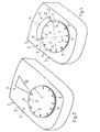
- toothbrushes 1 with a bristle holder 2 are shown in perspective.
- the the rear end of this bristle holder serves in a known manner as a handle 3, while the bristles 4 are attached to the front end of the bristle holder 2.
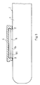
- the toothbrushes are further provided with a dating arrangement 5 which is only shown schematically and which will be explained in more detail with reference to FIGS. 3-11. 1, this dating arrangement 5 is located at the end of the handle 3, while in the toothbrush shown in FIG. 2, the dating arrangement 5 is provided in the front area of the handle 3.
- the dating arrangement 5 has a disk-shaped display element 6, which has the shape of a circle in plan view.
- This display element 6 is rotatably mounted in the handle 3 in a manner to be explained in more detail.
- the display element 6 is provided with a marking, generally designated 7, which is designed in the manner of a scale.
- the marking 7 has a number of division symbols 8, which are arranged at uniform intervals along the circumference of the display element 6. These division symbols 8 divide the circumference into twelve sections, each of which corresponds to a month of a year.
- the division symbols 8 are the numbers 1-12, which denote the individual time intervals (months) determined by the division symbols 8.
- the marker 7 is opposite a fixed marker 9 which interacts with the other marker 7.
- the marking 9 is formed by a single mark 10 which has the shape of a triangle.
- the marking 9 has two marks 11 and 12 designed as lines, which are arranged at a distance from one another. As shown in dashed lines, the marks 11 ', 12' can also be triangular. The distance between the marks 11 and 12 or 11 'and 12' essentially corresponds to three times the distance between adjacent division symbols 8 of the marking 7.
- the area 13 lying between the marks 11, 12 or 11 ', 12' can be visually emphasized be, e.g. through suitable coloring.
- the markings 7 and 9 can be adjusted to one another in order to obtain an indication of the date of use or the time of the necessary replacement of the toothbrush 1.
- either the division symbol 8 indicating the month of commissioning or the month in which the toothbrush has to be replaced is now aligned with the mark 10.
- the display element 6 is then locked in its position.
- the division symbol 8 opposite the mark 10 now shows when the toothbrush 1 was used for the first time or when a replacement of the toothbrush is due.
- the division symbol 8 which indicates the time of use, is brought into agreement with the mark 11 or 11 '.
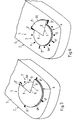
- markings 7 and 9 can also be interchanged, as is shown in FIGS. 5 and 6.
- the mark 7, which is designed similarly to the dial of a clock, is attached to the handle 3, the division symbols 8 being arranged in a uniformly distributed manner along a circular line.
- the division symbols 8 "denoting the months December, March, June and September are designed as lines, while the remaining division symbols are 8 points.
- the rotatable and lockable display element 6 mounted in the handle 3 consists of a disk-shaped lower part (base part) 6a and an upper part 6b, which is designed as a circular sector with a central angle of 270 ° (FIG. 5) or 90 ° (FIG. 6).
- the edges delimiting these circular sectors form the marks 11 and 12 of the marking 9.
- the period of use of the toothbrush is indicated by the sector 13 lying between these marks 11 and 12.
- the upper part 6b protrudes above the lower part 6a and completely covers part of the punctiform division symbols 8, while the division lines 8 ′′ located below the upper part 6b are only partly covered.
- the setting of the display element 6 takes place in the manner already explained in connection with FIG.
- the design of the display element 6 shown allows the latter to be produced in two colors without difficulty, e.g. in plastic injection molding.
- a two-color display element 6 can give the toothbrush a special appearance.
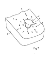
- FIG. 7 Another variant of the dating arrangement 5 is shown in FIG. 7.
- the mark 7 is also attached to the handle 3, for. B. imprinted on this.
- the division symbols 8 formed by numbers are evenly distributed along a circular line.
- the rotatable and lockable display element 6 has a part 6c in the form of a circular sector with a central angle of 90 °.
- the display element 6 can also be designed as a whole as a circular sector.
- the boundary edges of the circular sector 6c form the marks 11 and 12 of the marking 9.
- the radius of the display element 6 is smaller than the radius of the circle on which the division symbols 8 of the marking 7 lie, so that the latter always remains visible. Under certain circumstances, the circular sector 6c may be sloping towards its circumference.
- the embodiment according to FIG. 7 has the advantage over the very similar variant according to FIG. 6 that the production of the display element 6 is simpler and cheaper and that the marking 7 on the handle 3 is never covered.
- the marking 7 is also attached to the handle 3, specifically below the disc-shaped, rotatable display element 6.
- the display element 6 is transparent.
- the marks 11 and 12 of the marking 9 are attached to the display element 9.
- the sector 13 lying between the marks 11, 12 with a central angle of 90 ° (FIG. 8) or 13 ′ with a central angle of 270 ° (FIG. 9) z. B. be made opaque by color or less transparent than the rest of the display element.
- the marking 7 'can also be attached to the handle 3 in such a way that its division symbols 8' are not covered by the display element 6, as is indicated by dashed lines in FIG. 9.
- the division symbols 8 'can also be points and / or dashes instead of numbers, as is the case with the exemplary embodiments according to FIGS. 5 and 6.
- the display element 6 does not have to be made transparent. To facilitate the reading, it is sufficient to design the two sectors 13 and 13 ', which are separated from one another by the marks 11 and 12, in different colors.
- the display element 6 instead of as a disc similar to the parts 6b or 6c in the embodiments according to FIGS. 5-7 as a circular sector with a central angle of 90 ° or 270 °.
- the marks 11 and 12 of the marking 9 would likewise be formed by the edges delimiting these circular sectors.
- the marking 7 can also be applied to the transparent display element 6.
- the marks 11 and 12 of the marking 9, which are located below the display element 6 and are applied to the handle 3, are then to be designed such that they become visible through the display element 6.
- the sector 13 or 13 'lying between these marks 11 and 12 can also be highlighted by coloring.
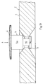
- the disk-shaped display element 6 sits on a shaft 14 which extends through an opening 15 in the handle. In many conventional toothbrushes, this opening 15 is already present at the end of the handle 3.
- the shaft 14 has three sections 14a, 14b and 14c, of which the sections 14a and 14c have a diameter which is larger than the diameter of the circular opening 15. By contrast, the central section 14b is smaller in diameter than the opening 15.
- the display element 6 In the position shown in FIG. 10, in which the shaft section 14b passes through the opening 15, the display element 6 is probably held in the bristle carrier 2, but can be rotated. After the markings 7 and 9 have been set, however, the display element 6 can be moved in the direction of its axis of rotation, e.g. lock in position in the direction of arrow A. If, as mentioned, pressure is exerted on the display element 6, the shaft section 14a is pressed into the opening 15 with elastic deformation thereof, whereby the display element 6 is secured against unintentional rotation.
- the display element 6 is seated on a bearing journal 16 which is molded onto the top of the bristle carrier 2.
- the lower part 16a of this journal 16 has a smaller diameter than the upper journal part 16b. With its lower, inwardly projecting edge 17, the display element 6 engages under this upper journal part 16b and is thus held rotatably on it.
- the locking of the display element 6 after setting the mark 7 and 9 is carried out in a manner not shown.
- the type of attachment of the display element 6 according to FIG. 11 has the advantage that no through opening has to be provided in the bristle carrier 2. This allows the dating arrangement 5 at the front end of the handle 3 to arrange, as shown in Fig. 2. 11 is particularly, but not exclusively, suitable for the embodiments shown in FIGS. 8 and 9, while the type of fastening according to FIG. 10 is particularly advantageous for the variants according to FIGS. 5-7.
- this display element 6 instead of making the display element 6 circular as shown in plan view, it is also possible to give the display element 6 a different shape. So this display element 6 in plan view z. B. have another radially symmetrical shape, in particular the shape of a regular polygon, for example a twelve-sided.
- All of the exemplary embodiments shown enable the user to easily date his toothbrush and to be able to easily determine at any time since when he has been using the toothbrush and when a replacement is due.
- the solutions shown are simple in construction and can also be manufactured inexpensively.
Landscapes
- Brushes (AREA)
Description
Die vorliegende Erfindung betrifft eine Zahnbürste gemäss Oberbegriff des Anspruches 1.The present invention relates to a toothbrush according to the preamble of claim 1.
Bekanntlich ist es aus hygienischen Gründen empfehlenswert, eine Zahnbürste nach einer gewissen Zeit, vorzugsweise nach drei Monaten seit der erstmaligen Benützung, zu ersetzen. Doch die wenigstens Benützer mögen sich noch des genauen Datums dieses erstmaligen Einsatzes zu entsinnen oder führen gar Buch über letzteren. Somit wissen die Benützer in der Regel die Einsatzdauer der von ihnen verwendeten Zahnbürste nicht. Das hat in den allermeisten Fällen zur Folge, dass die Zahnbürste zu lange in Gebrauch bleibt.As is well known, for reasons of hygiene, it is advisable to replace a toothbrush after a certain time, preferably three months after the first use. But the at least users may still remember the exact date of this first use or even keep a record of the latter. As a result, users generally do not know the duration of use of the toothbrush they are using. In most cases, this means that the toothbrush remains in use for too long.
Aus der DE-OS 2 405 403 ist nun eine Zahnbürste mit einer Datierungsanordnung bekannt, die ein Festhalten des Datums des Kaufes oder der Ingebrauchnahme ermöglicht. Zu diesem Zweck sind im Handgriff zwölf punktförmige, perforierbare Markierungsstellen vorgesehen, die entlang einer Geraden angeordnet sind. Mittels eines Stiftes wird nun die dem Monat des Kaufes bzw. der Ingebrauchnahme entsprechende Markierungsstelle durchstossen, so dass der Benützer jederzeit das Alter seiner Zahnbürste bestimmen kann.From DE-OS 2 405 403 a toothbrush with a dating arrangement is now known which enables the date of purchase or use to be recorded. For this purpose, twelve punctiform, perforable marking points are provided in the handle, which are arranged along a straight line. The marking point corresponding to the month of purchase or use is now pierced by means of a pen, so that the user can determine the age of his toothbrush at any time.
Diese bekannte Lösung hat nun den Nachteil, dass zum Durchstossen der Markierungen ein geeignetes Instrument erforderlich ist. Wird letzteres z.B. in der Form eines Stiftes der Zahnbürste beigelegt, so muss die Verpackung zur Aufnahme dieses Stiftes entsprechend ausgebildet werden. Zudem ist im Zuge des Verpackens ein zusätzlicher Schritt zum Beilegen des Stiftes zur Zahnbürste notwendig. Aber auch die Datierung ist verhältnismässig mühsam, erfordert doch das Durchstossen an der richtigen Markierungsstelle einiges Geschick. Ein Perforieren an der falschen Stelle kann zudem nicht ohne weiteres korrigiert werden.This known solution now has the disadvantage that a suitable instrument is required to pierce the markings. Is the latter e.g. enclosed in the form of a pen of the toothbrush, the packaging for receiving this pen must be designed accordingly. In addition, in the course of packaging, an additional step is required to insert the pencil into the toothbrush. But dating is also relatively tedious, since piercing the right marking requires some skill. Perforating in the wrong place can also not be easily corrected.
In der US-A-1 619 878 ist ein Löffel zum Einnehmen von dosierten Mengen eines Arzneimittels gezeigt, der mit einer Zeitanzeigeanordnung versehen ist. Diese Zeitanzeigeanordnung besteht aus einem am Ende des Löffelstieles angeordneten Zifferblatt und einem Zeiger. Mittels dieses Zeigers kann die Uhrzeit für die nächste Medikamenteneinnahme eingestellt werden. Diese Zeitanzeigeanordnung in der Art einer Uhr dient nun dazu, den Benützer daran zu erinnern, zu welcher Uhrzeit er die nächste Medikamentendosis einzunehmen hat.US-A-1 619 878 shows a spoon for taking dosed quantities of a medicament which is provided with a time display arrangement. This time display arrangement consists of a dial arranged at the end of the dipper arm and a pointer. With this pointer the time for the next medication can be set. This time display arrangement in the manner of a clock now serves to remind the user at what time he has to take the next dose of medication.
Daneben ist es weiter bekannt, Toilettengegenstände der verschiedensten Art mit einer Zeitanzeigeanordnung für die zeitliche Anzeige von einzuhaltenden Abmachungen zu versehen (CH-A-244861). Bei einer Ausführungsform einer solchen Zeitanzeigeanordnung sind zwei konzentrische Skalen vorhanden, von denen jede mit einem drehbar gelagerten Zeiger zusammenwirkt. Die eine Skala zeigt die Tage eines Monats an, während die andere Skala zum Anzeigen der Stunden eines Tages dient. Mittels der Zeiger lässt sich nun der Tag und die Stunde eines einzuhaltenden Termins einstellen.In addition, it is also known to provide toilet articles of various types with a time display arrangement for the time display of agreements to be kept (CH-A-244861). In one embodiment of such a time display arrangement there are two concentric scales, each of which interacts with a rotatably mounted pointer. One scale shows the days of a month, while the other scale shows the hours of a day. The day and hour of an appointment to be kept can now be set using the pointers.
Der vorliegenden Erfindung liegt nun die Aufgabe zugrunde, eine Zahnbürste der eingangs genannten Art zu schaffen, die einfach im Aufbau ist, möglichst wenig Teile aufweist und kostengünstig herstellbar ist und welche es dem Benützer erlaubt, ohne grossen Aufwand das richtige Datum der Ingebrauchnahme bzw. des Zeitpunktes des Ersatzes seiner Zahnbürste einzustellen.The present invention has for its object to provide a toothbrush of the type mentioned, which is simple in construction, has as few parts as possible and is inexpensive to manufacture and which allows the user, without great effort, the correct date of use or To set the time of the replacement of his toothbrush.
Diese Aufgabe wird erfindungsgemäss durch die Merkmale des kennzeichnenden Teils des Anspruches 1 gelöst.According to the invention, this object is achieved by the features of the characterizing part of claim 1.
Bei der Ingebrauchnahme der Zahnbürste kann der Benützer durch einfaches Drehen des mit dem Borstenträger verbundenen Anzeigeelementes die beiden Markierungen aufeinander einstellen, um so eine Anzeige des Datums der erstmaligen Benützung und/oder des Zeitpunktes des notwendigen Ersatzes der Zahnbürste zu erhalten. Für das Datieren ist somit kein separates Instrument notwendig. Der Benützer kann jederzeit durch einen Blick auf die Zahnbürste feststellen, wann er die Zahnbürste in Gebrauch genommen hat und wann diese zu ersetzen wäre. Mit der Datierungsanordnung wird somit - im Gegensatz zu den bekannten Zeitanzeigeanordnungen - eine für die Benützungsdauer der diese Datierungsanordnung tragenden Zahnbürste kennzeichnende Datumsangabe eingestellt.When the toothbrush is put into use, the user can adjust the two markings to one another simply by rotating the display element connected to the bristle holder, in order to obtain an indication of the date of first use and / or the time of the necessary replacement of the toothbrush. No separate instrument is therefore required for dating. By looking at the toothbrush, the user can determine at any time when he has used the toothbrush and when it should be replaced. In contrast to the known time display arrangements, the dating arrangement thus sets a date which characterizes the period of use of the toothbrush carrying this dating arrangement.
Im Gegensatz zu verderblichen Lebensmitteln und Arzneimitteln, bei denen die Zeitdauer, nach welcher kein Gebrauch mehr erfolgen sollte, mit dem Zeitpunkt der Herstellung, der Verpackung und des Verkaufes zu laufen beginnt, ist bei einer Zahnbürste nicht das Herstellungs-, Verpackungs-oder Verkaufsdatum von Wichtigkeit, sondern der Zeitpunkt der Ingebrauchnahme. Im Gegensatz zu den erwähnten Lebensmitteln und Arzneimitteln, bei denen die Datierung im Zuge der Herstellung bzw. Verpackung erfolgen kann, muss demzufolge bei einer Zahnbürste eine Datierung durch den Benützer nach dem Kauf der Zahnbürste möglich sein. Dieses Erfordernis wird durch den Erfindungsgegenstand auf einfache und zweckmässige Weise erfüllt.In contrast to perishable food and pharmaceuticals, in which the period after which use should cease to run starts with the time of manufacture, packaging and sale, the date of manufacture, packaging or sale of a toothbrush is not Importance, but the time of use. In contrast to the foods and pharmaceuticals mentioned, where the dating can take place in the course of manufacture or packaging, a toothbrush must therefore be able to be dated by the user after the toothbrush has been purchased. This requirement is met by the subject matter of the invention in a simple and expedient manner.
Bevorzugte Ausführungsformen der erfindungsgemässen Zahnbürste bilden Gegenstand der abhängigen Ansprüche.Preferred embodiments of the toothbrush according to the invention form the subject of the dependent claims.
Im folgenden werden an Hand der Zeichnung Ausführungsbeispiele des Erfindungsgegenstandes näher erläutert. Es zeigen rein schematisch perspektivisch, im Schnitt bzw. in Seitenansicht:
- Fig. 1 und 2 Zahnbürsten mit einer Datierungsanordnung,
- Fig. 3-9 in gegenüber den Fig. 1 und 2 vergrössertem Massstab das Ende des Zahnbürstengriffes mit verschiedenen Ausführungen der Datierungsanordnung,
- Fig. 10 einen Längsschnitt durch den die Datierungsanordnung aufweisenden Bereich des Zahnbürstengriffes, und
- Fig. 11 in teilweise geschnittener Seitenansicht das Ende des Zahnbürstengriffes mit der Datierungsanordnung.
- 1 and 2 toothbrushes with a dating arrangement,
- 3-9 on an enlarged scale compared to FIGS. 1 and 2, the end of the toothbrush handle with different versions of the dating arrangement,
- 10 shows a longitudinal section through the region of the toothbrush handle which has the dating arrangement, and
- 11 shows a partially sectioned side view of the end of the toothbrush handle with the dating arrangement.
In der Fig. 1 und 2 sind perspektivisch Zahnbürsten 1 mit einem Borstenträger 2 dargestellt. Das hintere Ende dieses Borstenträgers dient auf bekannte Weise als Griff 3, während am vordern Ende des Borstenträgers 2 die Borsten 4 angebracht sind. Die Zahnbürsten sind weiter mit einer nur schematisch dargestellten Datierungsanordnung 5 versehen, die an Hand der Fig. 3-11 noch näher zu erläutern sein wird. Beim Ausführungsbeispiel gemäss Fig. 1 befindet sich diese Datierungsanordnung 5 am Ende des Handgriffes 3, während bei der in Fig. 2 gezeigten Zahnbürste die Datierungsanordnung 5 im vordern Bereich des Handgriffes 3 vorgesehen ist.1 and 2, toothbrushes 1 with a
Wie die Fig. 3 und 4, in denen einander ähnliche Ausführungsformen dargestellt sind, zeigen, weist die Datierungsanordnung 5 ein scheibenförmiges Anzeigeelement 6 auf, das in Draufsicht die Form eines Kreises hat. Dieses Anzeigeelement 6 ist auf noch näher zu erläuternde Weise drehbar im Handgriff 3 gelagert. Das Anzeigeelement 6 ist mit einer allgemein mit 7 bezeichneten Markierung versehen, die in der Art einer Skala ausgebildet ist. Die Markierung 7 weist eine Anzahl von Teilungssymbolen 8 auf, die entlang des Kreisumfanges des Anzeigeelementes 6 in gleichmässigen Abständen verteilt angeordnet sind. Durch diese Teilungssymbole 8 wird der Kreisumfang in zwölf Abschnitte unterteilt, von denen jeder einem Monat eines Jahres entspricht. Im vorliegenden Fall sind die Teilungssymbole 8 die Zahlen 1-12, welche die einzelnen durch die Teilungssymbole 8 bestimmten Zeitintervalle (Monate) bezeichnen. Es versteht sich, das anstelle von Zahlen auch andere geeignete Symbole verwendet werden können, die eine Unterscheidung der einzelnen Monate erlauben. So ist es beispielsweise auch möglich, die Markierung 7 ähnlich zu gestalten wie bei Zifferblättern einer Uhr, also beispielsweise durch Teilstriche.3 and 4, in which similar embodiments are shown, the
Auf dem Handgriff 3 ist der Markierung 7 gegenüberliegend eine ortsfeste Markierung 9 angebracht, welche mit der andern Markierung 7 zusammenwirkt. Beim Ausführungsbeispiel gemäss Fig. 3 wird die Markierung 9 durch eine einzige Marke 10 gebildet, die die Form eines Dreiecks hat. Bei der in Fig. 4 gezeigten Variante weist die Markierung 9 zwei als Striche ausgebildete Marken 11 und 12 auf, die in einem Abstand voneinander angeordnet sind. Wie gestrichelt dargestellt, können die Marken 11', 12' auch dreieckförmig ausgebildet werden. Der Abstand zwischen den Marken 11 und 12 bzw. 11' und 12' entspricht im wesentlichen dem Dreifachen des Abstandes zwischen benachbarten Teilungssymbolen 8 der Markierung 7. Der zwischen den Marken 11, 12 bzw. 11', 12' liegende Bereich 13 kann optisch hervorgehoben werden, z.B. durch geeignete Farbgebung.On the
Durch Drehen des Anzeigeelementes 6 können die Markierungen 7 und 9 aufeinander eingestellt werden, um so eine Anzeige des Datums der Ingebrauchnahme bzw. des Zeitpunktes des notwendigen Ersatzes der Zahnbürste 1 zu erhalten. Bei der in Fig. 3 gezeigten Zahnbürste wird nun entweder das den Monat der Inbetriebnahme oder das den Monat, in welchem die Zahnbürste ersetzt werden muss, angebende Teilungssymbol 8 mit der Marke 10 ausgerichtet. Anschliessend wird das Anzeigeelement 6 in seiner Stellung arretiert. Das der Marke 10 gegenüberliegende Teilungssymbol 8 zeigt nun an, wann die Zahnbürste 1 erstmalig gebraucht wurde oder wann ein Ersatz der Zahnbürste fällig ist.By turning the
Bei der Ausführungsform gemäss Fig. 4 wird das den Zeitpunkt der Ingebrauchnahme bezeichnende Teilungssymbol 8 mit der Marke 11 bzw. 11' in Übereinstimmung gebracht. Die Marke 12 bzw. 12' zeigt nun auf der Markierung 7 an, in welchem Monat die Zahnbürste ersetzt werden soll. Gemäss der Darstellung in Fig. 4 ist somit die Zahnbürste im Dezember erstmalig benützt worden und ist demzufolge im nächsten März zu ersetzen. Die Variante gemäss Fig. 4 hat gegenüber der in Fig. gezeigten Ausführungsform den Vorteil, dass sowohl das Datum des erstmaligen Gebrauchs wie auch der Zeitpunkt des Ersatzes der Zahnbürste angezweigt wird.In the embodiment according to FIG. 4, the
Es ist nicht unbedingt erforderlich, jeden Monat durch ein Teilungssymbol 8 anzuzeigen. Wie in Fig. 4 gestrichelt dargestellt, können auch nur vier Teilungssymbole (Striche) 8' vorgesehen werden, die jeweils um einen Zentriwinkel von 90° auseinanderliegen. Durch jeweils zwei benachbarte Striche 8' wird ein Zeitintervall festgelegt, das einem Quartal entspricht. Die den einzelnen Quartalen zugeordneten Sektoren des Anzeigeelementes 6 können durch ein geeignetes Symbol bezeichnet werden, wie das durch die Buchstaben W, X, Y und Z angedeutet ist. So entspricht beispielsweise der mit W bezeichnete Sektor dem Winterquartal, der Sektor X dem Frühjahrsquartal, der Sektor Y dem Sommerquartal und der Sektor Z dem Herbstquartal.It is not absolutely necessary to display 8 with a division symbol every month. As shown in dashed lines in FIG. 4, only four division symbols (dashes) 8 'can be provided, each of which is spaced apart by a central angle of 90 °. A time interval which corresponds to a quarter is defined by two adjacent lines 8 '. The sectors of the
Es versteht sich, dass die Markierungen 7 und 9 auch vertauscht werden können, wie das in den Fig. 5 und 6 gezeigt ist. Die ähnlich wie das Zifferblatt einer Uhr ausgebildete Markierung 7 ist auf dem Handgriff 3 angebracht, wobei die Teilungssymbole 8 entlang einer Kreislinie gleichmässig verteilt angeordnet sind. Die die Monate Dezember, März, Juni und September bezeichnenden Teilungssymbole 8" sind als Striche ausgebildet, während die übrigen Teilungssymbole 8 Punkte sind.It goes without saying that the
Das drehbar und arretierbar im Handgriff 3 gelagerte Anzeigeelement 6 besteht aus einem scheibenförmigen Unterteil (Basisteil) 6a und einem Oberteil 6b, der als Kreissektor mit einem Zentriwinkel von 270° (Fig. 5) bzw. 90° (Fig. 6) ausgebildet ist. Die diese Kreissektoren begrenzenden Ränder bilden die Marken 11 und 12 der Markierung 9.The rotatable and
Durch den zwischen diesen Marken 11 und 12 liegenden Sektor 13 wird die Gebrauchsdauer der Zahnbürste angezeigt.The period of use of the toothbrush is indicated by the
Der Oberteil 6b steht über den Unterteil 6a vor und überdeckt einen Teil der punktförmigen Teilungssymbole 8 vollständig, während die unterhalb des Oberteils 6b liegenden Teilungsstriche 8" nur teilweise überdeckt werden.The upper part 6b protrudes above the
Die Einstellung des Anzeigeelementes 6 erfolgt auf die bereits in Zusammenhang mit der Fig.4 erläuterten Weise.The setting of the
Die gezeigte Ausbildung des Anzeigeelementes 6 erlaubt es, letzteres ohne Schwierigkeiten zweifarbig herzustellen, z.B. im Kunststoff-Spritzverfahren. Ein zweifarbig ausgestaltetes Anzeigeelement 6 vermag der Zahnbürste ein besonderes Aussehen zu verleihen.The design of the
Eine weitere Variante der Datierungsanordnung 5 ist in Fig. 7 dargestellt. Die Markierung 7 ist ebenfalls auf dem Handgriff 3 angebracht, z. B. auf diesen aufgeprägt. Die durch Zahlen gebildeten Teilungssymbole 8 sind entlang einer Kreislinie gleichmässig verteilt angeordnet. Das drehbare und arretierbare Anzeigeelement 6 weist einen Teil 6c in der Form eines Kreissektors mit einem Zentriwinkel von 90° auf. Das Anzeigeelement 6 kann jedoch auch als Ganzes als Kreissektor ausgebildet werden. Die Begrenzungsränder des Kreissektors 6c bilden die Marken 11 und 12 der Markierung 9. Der Radius des Anzeigeelementes 6 ist kleiner als der Radius des Kreises, auf dem die Teilungssymbole 8 der Markierung 7 liegen, so dass letztere immer sichtbar bleibt. Unter Umständen kann der Kreissektor 6c gegen seinen Umfang hin abfallend abgeschrägt sein.Another variant of the
Die Ausführungsform gemäss Fig. 7 hat gegenüber der sehr ähnlichen Variante gemäss Fig. 6 den Vorteil, dass die Herstellung des Anzeigeelementes 6 einfacher und billiger ist und dass die Markierung 7 auf dem Handgriff 3 nie verdeckt ist.The embodiment according to FIG. 7 has the advantage over the very similar variant according to FIG. 6 that the production of the
Bei den in den Fig. 8 und 9 gezeigten Ausführungsbeispielen ist die Markierung 7 ebenfalls auf dem Handgriff 3 angebracht, und zwar unterhalb des scheibenförmigen, drehbaren Anzeigeelementes 6. Um die Teilungssymbole 8 der Markierung 7 sichtbar zu machen, ist das Anzeigeelement 6 durchsichtig ausgebildet. Auf dem Anzeigeelement 9 sind die Marken 11 und 12 der Markierung 9 angebracht. Um die Ablesbarkeit zu erleichtern, dann der zwischen den Marken 11, 12 liegende Sektor 13 mit einem Zentriwinkel von 90° (Fig. 8) oder 13' mit einem Zentriwinkel von 270° (Fig. 9) z. B. durch Farbgebung undurchsichtig oder weniger durchsichtig gemacht werden als der übrige Bereich des Anzeigeelementes.In the exemplary embodiments shown in FIGS. 8 and 9, the marking 7 is also attached to the
Statt das Anzeigeelement 6 sektorweise durchsichtig bzw. undurchsichtig zu machen, ist es auch möglich, nur den oberhalb der Teilungssymbole 8 der Markierung 7 liegenden, kreisförmigen Randbereich des Anzeigeelementes 6 durchsichtig bwz. undurchsichtig zu gestalten.Instead of making the
Ähnlich wie bei der Ausführungsform gemäss Fig. 7 kann die Markierung 7' auch so auf dem Handgriff 3 angebracht werden, dass deren Teilungssymbole 8' durch das Anzeigeelement 6 nicht überdeckt werden, wie das in Fig. 9 gestrichelt angedeutet ist. Die Teilungssymbole 8' können dabei anstatt Zahlen auch Punkte und/oder Striche sein, wie das bei den Ausführungsbeispielen gemäss den Fig. 5 und 6 der Fall ist. Das Anzeigeelement 6 muss nicht durchsichtig ausgestaltet werden. Zur Erleichterung des Ablesens genügt es, die beiden durch die Marken 11 und 12 voneinander getrennten Sektoren 13 und 13' verschiedenfarbig auszubilden.Similar to the embodiment according to FIG. 7, the marking 7 'can also be attached to the
Ferner ist es denkbar, das Anzeigeelement 6 statt als Scheibe ähnlich wie die Teile 6b bzw. 6c bei den Ausführungsformen gemäss den Fig. 5-7 als Kreissektor mit einem Zentriwinkel von 90° bzw. 270° auszubilden. Die Marken 11 und 12 der Markierung 9 würden in diesem Fall ebenfalls durch die diese Kreissektoren begrenzenden Ränder gebildet.Furthermore, it is conceivable to design the
Ferner kann die Markierung 7 auch auf dem durchsichtigen Anzeigeelement 6 angebracht werden. Die unterhalb des Anzeigeelementes 6 liegenden, auf den Handgriff 3 aufgebrachten Marken 11 und 12 der Markierung 9 sind dann so auszugestalten, dass sie durch das Anzeigeelement 6 hindurch sichtbar werden. Der zwischen diesen Marken 11 und 12 liegende Sektor 13 bzw. 13' kann ebenfalls durch Farbgebung hervorgehoben werden.Furthermore, the marking 7 can also be applied to the
Anhand der Fig. 10 und 11 werden im folgenden Möglichkeiten zur Befestigung des Anzeigeelementes 6 am Borstenträger 2 erläutert.10 and 11, options for fastening the
Bei der Variante gemäss Fig. 10 sitzt das scheibenförmige Anzeigeelement 6 auf einer Welle 14, die sich durch eine Öffnung 15 im Handgriff hindurcherstreckt. Diese Öffnung 15 ist bei vielen herkömmlichen Zahnbürsten bereits jetzt schon am Ende des Handgriffes 3 vorhanden. Die Welle 14 weist drei Abschnitte 14a, 14b und 14c auf, von denen die Abschnitte 14a und 14c einen Durchmesser aufweisen, der grösser ist als der Durchmesser der kreisförmigen Öffnung 15. Der mittlere Abschnitt 14b ist hingegen kleiner im Durchmesser als die Öffnung 15. In der in Fig. 10 gezeigten Position, in der der Wellenabschnitt 14b die Öffung 15 durchsetzt, ist das Anzeigeelement 6 wohl im Borstenträger 2 gehalten, lässt sich jedoch drehen. Nach erfolgter Einstellung der Markierungen 7 und 9 lässt sich jedoch das Anzeigeelement 6 durch Druckeinwirkung in Richtung seiner Drehachse, d.h. in Richtung des Pfeiles A, in seiner Stellung arretieren. Wird auf das Anzeigeelement 6 - wie erwähnt - ein Druck ausgeübt, so wird der Wellenabschnitt 14a unter elastischer Deformierung desselben in die Öffnung 15 hineingedrückt, wodurch das Anzeigeelement 6 gegen ein unbeabsichtigtes Verdrehen gesichert wird.In the variant according to FIG. 10, the disk-shaped
Bei der in Fig. 11 gezeigten Ausführung sitzt das Anzeigeelement 6 auf einem Lagerzapfen 16, der an der Oberseite des Borstenträgers 2 angeformt ist. Der untere Teil 16a dieses Lagerzapfens 16 weist einen kleinern Durchmesser auf als der obere Lagerzapfenteil 16b. Das Anzeigeelement 6 untergreift mit seinem untern, nach innen vorspringenden Rand 17 diesen obern Lagerzapfenteil 16b und wird so an diesem drehbar gehalten. Die Arretierung des Anzeigeelementes 6 nach erfolgter Einstellung der Markierung 7 und 9 erfolgt auf nicht näher dargestellte Weise.In the embodiment shown in FIG. 11, the
Die Befestigungsart des Anzeigeelementes 6 gemäss Fig. 11 hat den Vorteil, dass im Borstenträger 2 keine Durchgangsöffnung vorgesehen werden muss. Das erlaubt es, die Datierungsanordnung 5 am vordern Ende des Handgriffes 3 anzuordnen, wie das in Fig. 2 dargestellt ist. Die Ausführung gemäss Fig. 11 eignet sich besonders, jedoch nicht ausschliesslich, für die in den Fig. 8 und 9 dargestellten Ausführungformen, während die Befestigungsart gemäss Fig. 10 insbesondere bei den Varianten gemäss den Fig. 5-7 vorteilhaft ist.The type of attachment of the
Anstatt das Anzeigeelement 6 - wie gezeigt - in Draufsicht kreisförmig auszubilden, ist es auch möglich, dem Anzeigeelement 6 eine andere Form zu geben. So kann dieses Anzeigeelement 6 in Draufsichtz. B. eine andere radialsymmetrische Form aufweisen, insbesondere die Form eines regelmässigen Vielecks, beispielsweise eines Zwölfecks.Instead of making the
Bei der Erläuterung der Ausführungsbeispiele wurde davon ausgegangen, dass eine Zahnbürste nicht länger als drei Monate in Gebrauch stehen sollte. Falls sich an dieser heute als zweckmässig erachteten Gebrauchsdauer etwas ändern sollte, so müsste der Abstand der beiden Marken 10 und 11 der Markierung 9 entsprechend geändert werden.In the explanation of the exemplary embodiments, it was assumed that a toothbrush should not be used for longer than three months. If anything should change in this period of use, which is considered to be expedient today, the distance between the two
Alle gezeigten Ausführungsbeispiele ermöglichen es dem Benützer, auf einfache Weise eine Datierung seiner Zahnbürste vorzunehmen und jederzeit mühelos feststellen zu können, seit wann er die Zahnbürste benützt und wann ein Ersatz derselben fällig wird. Die gezeigten Lösungen sind einfach im Aufbau und lassen sich auch kostengünstig herstellen.All of the exemplary embodiments shown enable the user to easily date his toothbrush and to be able to easily determine at any time since when he has been using the toothbrush and when a replacement is due. The solutions shown are simple in construction and can also be manufactured inexpensively.
Claims (17)
Applications Claiming Priority (2)
| Application Number | Priority Date | Filing Date | Title |
|---|---|---|---|
| DE3140903 | 1981-10-15 | ||
| DE3140903A DE3140903C2 (en) | 1981-10-15 | 1981-10-15 | toothbrush |
Publications (3)
| Publication Number | Publication Date |
|---|---|
| EP0077484A2 EP0077484A2 (en) | 1983-04-27 |
| EP0077484A3 EP0077484A3 (en) | 1985-01-16 |
| EP0077484B1 true EP0077484B1 (en) | 1988-06-22 |
Family
ID=6144133
Family Applications (1)
| Application Number | Title | Priority Date | Filing Date |
|---|---|---|---|
| EP82109087A Expired EP0077484B1 (en) | 1981-10-15 | 1982-10-01 | Toothbrush |
Country Status (4)
| Country | Link |
|---|---|
| US (1) | US4466150A (en) |
| EP (1) | EP0077484B1 (en) |
| JP (2) | JPS5883907A (en) |
| DE (1) | DE3140903C2 (en) |
Families Citing this family (23)
| Publication number | Priority date | Publication date | Assignee | Title |
|---|---|---|---|---|
| JPS6070335U (en) * | 1983-10-24 | 1985-05-18 | 三洋電機株式会社 | electric toothbrush |
| JPS6091036U (en) * | 1983-11-30 | 1985-06-21 | サンスター株式会社 | toothbrush |
| JPS61167835U (en) * | 1985-04-06 | 1986-10-17 | ||
| JPS61172541U (en) * | 1985-04-17 | 1986-10-27 | ||
| FR2588169B1 (en) * | 1985-10-04 | 1991-12-27 | Benarrouch Jacques | TEETH NECESSARY FOR THE INITIATION OF CHILDREN IN DENTAL HYGIENE |
| DE3836232C1 (en) * | 1988-10-25 | 1990-03-29 | Erwin 8000 Muenchen De Roth | |
| DE9000747U1 (en) * | 1990-01-24 | 1990-07-12 | Pai, Chung-Jen, Pan Chiao City, Taipeh | toothbrush |
| GB2252234A (en) * | 1991-02-02 | 1992-08-05 | Richard David Baker | Timing toothbrush |
| DE4207755A1 (en) * | 1992-03-11 | 1993-09-23 | Foldenauer Willi | PEN-LIKE DEVICE |
| IES72108B2 (en) * | 1996-09-16 | 1997-03-12 | Neill Edward O | Improvements in and relating to devices for indicating usage of an article |
| US5839578A (en) | 1997-03-24 | 1998-11-24 | Rxtra Inc. | Health improvement device for modifiying a daily behavior by reminding a person to take medication |
| US6053338A (en) | 1997-11-25 | 2000-04-25 | Rxtra, Inc. | Adjustable health improvement device for modifying a daily behavior by reminding a person to take medication |
| US9027192B1 (en) * | 2002-10-30 | 2015-05-12 | Mandy Cole | Toothbrush with usage indicator |
| US6994227B2 (en) * | 2003-02-11 | 2006-02-07 | Man-Hyun Kwon | vacuum container to preserve food |
| US20040182733A1 (en) * | 2003-03-17 | 2004-09-23 | Dunlap David L. | Toothbrush package with sequentially dated toothbrushes |
| US20050246943A1 (en) * | 2004-05-10 | 2005-11-10 | Hermann Neumann | Multi-season pest control system and method |
| US20090050500A1 (en) * | 2007-08-23 | 2009-02-26 | Judith Ultimo | Device for reminding the user when to dispose of a toothbrush |
| US20100136874A1 (en) * | 2008-12-03 | 2010-06-03 | Moss David B | Toothbrush and amusement device |
| US8434421B2 (en) * | 2009-09-22 | 2013-05-07 | Janet L. Fagan | Manually settable tamper resistant indicator device |
| CN102298432B (en) * | 2010-06-23 | 2015-04-01 | 鸿富锦精密工业(深圳)有限公司 | Battery holder |
| US8453592B2 (en) * | 2011-03-21 | 2013-06-04 | Timothy Edwards | Animal feeding reminder system |
| US10206766B2 (en) | 2016-08-04 | 2019-02-19 | Airway Medix S.A. | Toothbrush system for treating intubated patients |
| US10299978B2 (en) * | 2016-10-02 | 2019-05-28 | Airway Medix S.A | System, method and kit for oral care |
Family Cites Families (18)
| Publication number | Priority date | Publication date | Assignee | Title |
|---|---|---|---|---|
| US427254A (en) * | 1890-05-06 | Caul danielowsky | ||
| GB191411122A (en) * | 1914-05-06 | 1915-05-06 | William Farley Hills | Improvements in Time Indicators as Applied to the Administration of Foods, Medicines, and such like. |
| US1370956A (en) * | 1920-10-26 | 1921-03-08 | David L Fish | Medicine-taking-time indicator |
| DE405403C (en) * | 1921-01-21 | 1924-11-04 | A C Pohlmann Fa | Concrete roof plate with edge strips |
| US1619878A (en) * | 1924-11-13 | 1927-03-08 | Morgan | Dosage spoon |
| US1582589A (en) * | 1925-12-28 | 1926-04-27 | Exline Marcus Page | Identifying device |
| GB298379A (en) * | 1927-10-31 | 1928-10-11 | Johannes Freng | Improvements in advertising apparatus |
| US2471680A (en) * | 1944-06-10 | 1949-05-31 | Jr George A Gibson | Toothbrush handle |
| CH244861A (en) * | 1945-10-03 | 1946-10-15 | A Wirth Kurt | Toilet object. |
| US2489707A (en) * | 1946-09-27 | 1949-11-29 | Floyd G Eubanks | Toothbrush with identification means |
| US2450949A (en) * | 1947-06-18 | 1948-10-12 | Gattuccio Salvadore | Bottle cap |
| US3921568A (en) * | 1973-07-25 | 1975-11-25 | William Joseph Fish | Self-adhering medication time reminder |
| DE2405403A1 (en) * | 1974-02-05 | 1975-08-07 | Horst Moch | Tooth brush with indication of length of use - has hole punched through any one of 12 points indicating month bought |
| DE2408535A1 (en) * | 1974-02-22 | 1975-09-18 | Horst Moch | Toothbrush handle with sales month indication - has hole at handle end for irremovable insertion of month indicator disc |
| JPS5422255Y2 (en) * | 1975-10-14 | 1979-08-03 | ||
| DE2652251A1 (en) * | 1976-11-16 | 1978-05-18 | Brehm Heide | Mechanical data recording card - has array of manually rotatable data recording elements |
| JPS53120880A (en) * | 1977-03-29 | 1978-10-21 | Nippon Kouden Kougiyou Kk | Lung function measuring instrument |
| US4347804A (en) * | 1980-02-12 | 1982-09-07 | Medi-Timer Corporation | Mono-disc rotatory medication reminder |
-
1981
- 1981-10-15 DE DE3140903A patent/DE3140903C2/en not_active Expired
-
1982
- 1982-10-01 EP EP82109087A patent/EP0077484B1/en not_active Expired
- 1982-10-04 US US06/432,433 patent/US4466150A/en not_active Expired - Lifetime
- 1982-10-15 JP JP57181191A patent/JPS5883907A/en active Pending
-
1991
- 1991-07-30 JP JP1991067291U patent/JPH0495731U/ja active Pending
Also Published As
| Publication number | Publication date |
|---|---|
| JPS5883907A (en) | 1983-05-19 |
| DE3140903C2 (en) | 1985-08-22 |
| US4466150A (en) | 1984-08-21 |
| EP0077484A2 (en) | 1983-04-27 |
| EP0077484A3 (en) | 1985-01-16 |
| JPH0495731U (en) | 1992-08-19 |
| DE3140903A1 (en) | 1983-05-05 |
Similar Documents
| Publication | Publication Date | Title |
|---|---|---|
| EP0077484B1 (en) | Toothbrush | |
| DE1909694A1 (en) | Device for setting up a preparation plan for meals | |
| DE440189C (en) | Perpetual calendar | |
| DE1963461C3 (en) | Calendar valid over a number of years | |
| DE889995C (en) | Annual rotating calendar, especially on pens and the like like | |
| DE3904980A1 (en) | Device for determining process data for the colouring of hair | |
| DE922197C (en) | Adjustable calendar | |
| DE8433302U1 (en) | Calculating device for determining the fertile or sterile days of a menstrual period | |
| DE8807144U1 (en) | Map knife | |
| DE8909572U1 (en) | Filter device for drinking water | |
| DE421291C (en) | Perpetual calendar | |
| DE2336948C3 (en) | Micrometer with digital reading | |
| DE398294C (en) | Note device | |
| DE1240713B (en) | Device for temperature adjustment for heat devices or the like. | |
| DE378079C (en) | Calendar with rotating discs | |
| DE2156404C3 (en) | Device for correcting the declination of a magnetic compass | |
| DE2207665A1 (en) | WRITING DEVICE, IN PARTICULAR BALLPOINT PEN WITH DATE DISPLAY | |
| CH342018A (en) | Conception indicator | |
| DE2718227A1 (en) | Calendar with day highlighting device - uses adjustable lens mounted on movable sliding band attached to base plate | |
| DE1833027U (en) | DEVICE FOR CONTROLLING THE PARKING TIME OF MOTOR VEHICLES. | |
| DE1123290B (en) | Note calendar | |
| DE8901928U1 (en) | Device for determining process data for dyeing hair | |
| DE1960788U (en) | CONTAINER FOR DRUGS IN PIECE FORM. | |
| DE9202853U1 (en) | Data carrier made of two rotatably connected disks | |
| DE321413T1 (en) | CLOCK WITH DEVICE FOR DETERMINING THE PULSE SHOCK. |
Legal Events
| Date | Code | Title | Description |
|---|---|---|---|
| PUAI | Public reference made under article 153(3) epc to a published international application that has entered the european phase |
Free format text: ORIGINAL CODE: 0009012 |
|
| AK | Designated contracting states |
Designated state(s): CH FR GB IT LI NL SE |
|
| PUAL | Search report despatched |
Free format text: ORIGINAL CODE: 0009013 |
|
| AK | Designated contracting states |
Designated state(s): CH FR GB IT LI NL SE |
|
| 17P | Request for examination filed |
Effective date: 19850119 |
|
| ITF | It: translation for a ep patent filed | ||
| GRAA | (expected) grant |
Free format text: ORIGINAL CODE: 0009210 |
|
| AK | Designated contracting states |
Kind code of ref document: B1 Designated state(s): CH FR GB IT LI NL SE |
|
| ET | Fr: translation filed | ||
| GBT | Gb: translation of ep patent filed (gb section 77(6)(a)/1977) | ||
| PLBE | No opposition filed within time limit |
Free format text: ORIGINAL CODE: 0009261 |
|
| STAA | Information on the status of an ep patent application or granted ep patent |
Free format text: STATUS: NO OPPOSITION FILED WITHIN TIME LIMIT |
|
| 26N | No opposition filed | ||
| ITTA | It: last paid annual fee | ||
| EAL | Se: european patent in force in sweden |
Ref document number: 82109087.5 |
|
| PGFP | Annual fee paid to national office [announced via postgrant information from national office to epo] |
Ref country code: NL Payment date: 19980914 Year of fee payment: 17 Ref country code: GB Payment date: 19980914 Year of fee payment: 17 |
|
| PGFP | Annual fee paid to national office [announced via postgrant information from national office to epo] |
Ref country code: SE Payment date: 19980918 Year of fee payment: 17 |
|
| PG25 | Lapsed in a contracting state [announced via postgrant information from national office to epo] |
Ref country code: GB Free format text: LAPSE BECAUSE OF NON-PAYMENT OF DUE FEES Effective date: 19991001 |
|
| PG25 | Lapsed in a contracting state [announced via postgrant information from national office to epo] |
Ref country code: SE Free format text: THE PATENT HAS BEEN ANNULLED BY A DECISION OF A NATIONAL AUTHORITY Effective date: 19991030 |
|
| PG25 | Lapsed in a contracting state [announced via postgrant information from national office to epo] |
Ref country code: NL Free format text: LAPSE BECAUSE OF NON-PAYMENT OF DUE FEES Effective date: 20000501 |
|
| GBPC | Gb: european patent ceased through non-payment of renewal fee |
Effective date: 19991001 |
|
| EUG | Se: european patent has lapsed |
Ref document number: 82109087.5 |
|
| NLV4 | Nl: lapsed or anulled due to non-payment of the annual fee |
Effective date: 20000501 |
|
| PGFP | Annual fee paid to national office [announced via postgrant information from national office to epo] |
Ref country code: FR Payment date: 20011011 Year of fee payment: 20 |
|
| PGFP | Annual fee paid to national office [announced via postgrant information from national office to epo] |
Ref country code: CH Payment date: 20011029 Year of fee payment: 20 |
|
| PG25 | Lapsed in a contracting state [announced via postgrant information from national office to epo] |
Ref country code: LI Free format text: LAPSE BECAUSE OF EXPIRATION OF PROTECTION Effective date: 20020930 Ref country code: CH Free format text: LAPSE BECAUSE OF EXPIRATION OF PROTECTION Effective date: 20020930 |
|
| REG | Reference to a national code |
Ref country code: CH Ref legal event code: PL |