EP0077280B1 - Aufrichtstuhl - Google Patents
Aufrichtstuhl Download PDFInfo
- Publication number
- EP0077280B1 EP0077280B1 EP19820420138 EP82420138A EP0077280B1 EP 0077280 B1 EP0077280 B1 EP 0077280B1 EP 19820420138 EP19820420138 EP 19820420138 EP 82420138 A EP82420138 A EP 82420138A EP 0077280 B1 EP0077280 B1 EP 0077280B1
- Authority
- EP
- European Patent Office
- Prior art keywords
- links
- shell
- axis
- stand
- articulation
- Prior art date
- Legal status (The legal status is an assumption and is not a legal conclusion. Google has not performed a legal analysis and makes no representation as to the accuracy of the status listed.)
- Expired
Links
Images
Classifications
-
- A—HUMAN NECESSITIES
- A61—MEDICAL OR VETERINARY SCIENCE; HYGIENE
- A61G—TRANSPORT, PERSONAL CONVEYANCES, OR ACCOMMODATION SPECIALLY ADAPTED FOR PATIENTS OR DISABLED PERSONS; OPERATING TABLES OR CHAIRS; CHAIRS FOR DENTISTRY; FUNERAL DEVICES
- A61G5/00—Chairs or personal conveyances specially adapted for patients or disabled persons, e.g. wheelchairs
- A61G5/10—Parts, details or accessories
- A61G5/14—Standing-up or sitting-down aids
Definitions
- the present invention relates to a lift chair of the “monocoque” type, comprising a base, an ascent-descent mechanism and a shell composed of a seat, a backrest and two armrests joined together in a monobloc assembly, the mechanism uphill-down comprising two parallel and identical articulated systems arranged on the two opposite sides of the chair, each composed of two rods of unequal length, which each connect the base to the shell so that each system forms a deformable quadrilateral, the two rods of shorter length having their axis of articulation on the base located higher than the axis of articulation of the two rods of greater length on the base, while an extendable motorized device is articulated, on the one hand, to the base along a transverse axis and, on the other hand, to the shell along an axis parallel to the axis of articulation of the rods of shorter length to said shell.
- a lift chair of this kind already described in patent CH-A-600 384, provides elderly or disabled people with assistance for the transition from the sitting position to the standing position, therefore for lifting, as well as for the passage reverse from standing to sitting position.
- This chair allows such people to get up or sit down without the help of a third person and without physical effort.
- the present invention aims to remedy these drawbacks by providing a lifting chair of the “monocoque” type, which is of simple and light construction, while having a particularly suitable movement and also allowing possible adjustments as a function of the size of user and / or the desired seating position.
- the subject of the invention is a lift chair of the type indicated above, in which the axis of articulation on the base of the two rods of shorter length is moreover arranged behind the axis of articulation on the base of the two rods of greater length, and in which the axis of articulation between the extendable motorized device and the shell is, moreover, coincident with the axis of articulation of the rods of shorter length at said shell.
- the lifting chair object of the present invention has a lifting mechanism in which the unequal length of the links and the position of the articulation axes give, on ascent, a remarkable movement: the shell of the chair rises first by remaining roughly parallel to itself, and it is only then that this hull tilts forward, while continuing its movement of elevation.
- This movement can be ensured in particular by means of rods, the two shortest of which have a length less than half that of the two longest rods, and more particularly still by providing that the ratio between the lengths of the rods is approximately equal to 2 / 5. Furthermore, the simplicity of the lifting mechanism. which has a reduced number of axes of articulation, results in the lightness of the entire chair, allowing its easy movement by the user or by a person close to him.
- the two shorter rods are articulated at points located near the anterior edge of vertical lateral elements integral with the shell, while the two longer rods are articulated in points located near the rear edge of said elements, the latter comprising a series of holes which allow the height of the articulation points of the two pairs of rods to be adjusted.
- Said vertical lateral elements are, for example, legs folded downwards, which belong to a plate fixed under the seat of the shell.
- the series of holes, provided in the latter case along the anterior and posterior edges of each lateral tab of the plate, allow an initial adjustment of the height relative to the ground of the shell, as well as of the inclination of the seat. with respect to the horizontal.
- each pair of rods of equal length is integral with the same transverse tube, pivotally mounted along its axis between the two lateral parts of the base, the two rods more short length also being interconnected by a cross member carrying in its middle a yoke to which is articulated, along an axis passing through the points of articulation of these rods on the shell, the upper end of a threaded rod moved axially at by means of a rotary nut coupled to an electric geared motor, the threaded rod being partially housed inside a housing secured to the geared motor and articulated to the base along a transverse axis.
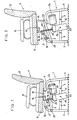
- the armchair shown in the drawing comprises a metal base (1), two identical and parallel articulated systems arranged on the two opposite sides (1), of the armchair, each system being composed of two rods (2, 3) of unequal lengths, each connecting the base with a shell (4).
- the base (1) has, on each side, a front upright (5) and a rear upright (6), interconnected by a right upper element (7) as well as by a bent lower bar (8).
- the two bars (8) are connected to each other by two transverse elements (9), which with the middle parts of these bars (8) define a small rectangular central frame (10).
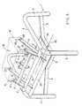
- the shell (4) consists of a seat (11), a backrest (12) and two armrests (13), joined together as a single unit. Under the seat (11) is fixed a plate (14), the side parts of which are folded so as to form two vertical legs (15) facing downwards.
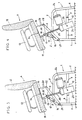
- the first pair of connecting rods (2) of equal length is integral with the same transverse tube (16), pivotally mounted along its axis between the front parts of the two upper elements (7) of the base (1). These two rods (2) are also connected to each other at intermediate points of their length, by a crosspiece (17), while their ends remote from the tube (16) are articulated, at points (18), near the front edges. of the two lateral tabs (15) of the plate (14).
- the crosspiece (17) carries two ears (19), constituting a yoke whose axis (20) passes through the points of articulation (18) of the rods (2) on the lateral legs (15) of the plate (14).
- the second pair of connecting rods (3) of equal length is also integral with the same transverse tube (21), pivotally mounted along its axis between the upper parts of the two front uprights (5) of the base (1).
- the ends of these links (3) remote from the tube (21) are articulated, at points (22), near the rear edges of the two lateral tabs (15) of the plate (14).
- the links (3) of the second pair have a length greater than twice that of the links (2) of the first pair.
- the length of the rods (2) (measured between the two articulation axes) is 12.5 cm
- the length of the rods (3) (measured between the two articulation axes) is 31, 5 cm, which corresponds to a length ratio very close to 2/5.
- the axis of articulation of the connecting rods (2) of shorter length on the base (1) is located above and behind the axis of articulation rods (3) of greater length on the base (1).
- the axis of the tube (16) is located 8.5 cm higher than the axis of the tube (21), and 5 cm in back of the latter.
- the central frame (10) of the base (1) is crossed by a housing (23) integral with an electric geared motor (24), which rotates a nut (not shown) cooperating with a threaded rod (25) of which the part outside the housing (23) is directed upwards.
- the housing is linked to the two bars (8) by articulation along a transverse axis (26); the upper end of the threaded rod (25) is articulated to the yoke (19) along the axis (20).
- Figures 1 to 4 make it possible to decompose the movement which brings the shell (4) from its lowest position to its highest position, this movement being controlled by the actuation of the gear motor (24) in the direction causing the lifting of the threaded rod (25) relative to the housing (23).
- Each side tab (15) of the plate (14) has, along its front and rear edges, series of holes respectively (27 and 28), allowing positioning in various ways the articulation points (18 and 22) of the links (2 and 3), to adjust the height and the inclination of the shell (4) in the low position.
- the manual control of the gear motor (24) will advantageously be placed on one of the armrests (13) of the shell (4).
Landscapes
- Health & Medical Sciences (AREA)
- Life Sciences & Earth Sciences (AREA)
- Animal Behavior & Ethology (AREA)
- General Health & Medical Sciences (AREA)
- Public Health (AREA)
- Veterinary Medicine (AREA)
- Chairs Characterized By Structure (AREA)
- Chairs For Special Purposes, Such As Reclining Chairs (AREA)
Claims (6)
Applications Claiming Priority (2)
| Application Number | Priority Date | Filing Date | Title |
|---|---|---|---|
| FR8118827 | 1981-10-01 | ||
| FR8118827A FR2513876A1 (fr) | 1981-10-01 | 1981-10-01 | Fauteuil elevateur |
Publications (2)
| Publication Number | Publication Date |
|---|---|
| EP0077280A1 EP0077280A1 (de) | 1983-04-20 |
| EP0077280B1 true EP0077280B1 (de) | 1986-05-28 |
Family
ID=9262804
Family Applications (1)
| Application Number | Title | Priority Date | Filing Date |
|---|---|---|---|
| EP19820420138 Expired EP0077280B1 (de) | 1981-10-01 | 1982-09-29 | Aufrichtstuhl |
Country Status (4)
| Country | Link |
|---|---|
| EP (1) | EP0077280B1 (de) |
| DE (1) | DE3271399D1 (de) |
| ES (1) | ES8306319A1 (de) |
| FR (1) | FR2513876A1 (de) |
Cited By (2)
| Publication number | Priority date | Publication date | Assignee | Title |
|---|---|---|---|---|
| DE3815435A1 (de) * | 1988-05-06 | 1989-11-16 | Dieter Schaller | Sitzmoebel mit einem um eine schwenkachse nach vorn hochklappbaren sitz |
| EP3650000A1 (de) | 2018-11-09 | 2020-05-13 | Costola, Valentino | Vorrichtung zum heben von personen, die mit dem sitz eines stuhls oder eines sessels verbunden werden kann |
Families Citing this family (14)
| Publication number | Priority date | Publication date | Assignee | Title |
|---|---|---|---|---|
| US4587678A (en) * | 1985-02-04 | 1986-05-13 | Love Larry W | Toilet seat booster |
| GB2183150A (en) * | 1985-09-26 | 1987-06-03 | Cluney Upholstery Limited | Chair |
| GB2205230B (en) * | 1987-04-24 | 1990-06-06 | Cinnamon Limited J | Chair |
| US4852939A (en) * | 1987-10-23 | 1989-08-01 | Orthokinetics, Inc. | Device for converting a recliner chair to a recliner-lift chair |
| CA1299989C (en) * | 1988-05-20 | 1992-05-05 | Larry P. Lapointe | Recliner chair lift base assembly |
| US4946222A (en) * | 1989-01-30 | 1990-08-07 | Triangle Engineering Of Arkansas, Inc. | Lift platform for chairs |
| FR2663218B1 (fr) * | 1990-06-15 | 1993-04-23 | Tanis | Fauteuil motorise avec assistance des mouvements verticaux de l'utilisateur. |
| US5178025A (en) * | 1990-08-31 | 1993-01-12 | Innovative Medical Engineering, Inc. | Tiltable lift seat devices |
| AU6354194A (en) * | 1993-03-02 | 1994-09-26 | Kenneth Casey | Universal lift frame for a chair |
| US5458349A (en) * | 1994-06-30 | 1995-10-17 | Mung-Tung; Wang | Multi-function electric wheel-chair |
| NL1001998C2 (nl) * | 1995-12-28 | 1997-07-02 | Doge Collection B V | Hef-kantelmechanisme. |
| GB2412847B (en) * | 2004-04-07 | 2006-10-11 | Charles Basil Firth | Wheelchair with elevating seat |
| WO2008005049A2 (en) * | 2006-06-30 | 2008-01-10 | I-Trust Better Life Corp. | A lift chair and a chair base frame with an acuator for use therewith |
| ATE460147T1 (de) * | 2006-08-21 | 2010-03-15 | Opruga D D | Sitzmöbel mit hubantrieb zur unterstützung beim aufstehen |
Family Cites Families (5)
| Publication number | Priority date | Publication date | Assignee | Title |
|---|---|---|---|---|
| GB926157A (en) * | 1960-06-30 | 1963-05-15 | Frederick Edward Rule Hooper | Invalid chairs or the like |
| US3091426A (en) * | 1961-05-08 | 1963-05-28 | Arthur J Klein | Adjustable chair |
| US3138402A (en) * | 1961-11-01 | 1964-06-23 | American Metal Prod | Invalid chair |
| CH600834A5 (en) * | 1975-10-24 | 1978-06-30 | Truffart Demont Nelly | Elevating and tipping chair for aged or infirm |
| US4083599A (en) * | 1976-04-16 | 1978-04-11 | Gaffney Edward J | Lift chair with rocker and wheel frame attachments |
-
1981
- 1981-10-01 FR FR8118827A patent/FR2513876A1/fr active Granted
-
1982
- 1982-09-29 DE DE8282420138T patent/DE3271399D1/de not_active Expired
- 1982-09-29 EP EP19820420138 patent/EP0077280B1/de not_active Expired
- 1982-09-30 ES ES516118A patent/ES8306319A1/es not_active Expired
Cited By (2)
| Publication number | Priority date | Publication date | Assignee | Title |
|---|---|---|---|---|
| DE3815435A1 (de) * | 1988-05-06 | 1989-11-16 | Dieter Schaller | Sitzmoebel mit einem um eine schwenkachse nach vorn hochklappbaren sitz |
| EP3650000A1 (de) | 2018-11-09 | 2020-05-13 | Costola, Valentino | Vorrichtung zum heben von personen, die mit dem sitz eines stuhls oder eines sessels verbunden werden kann |
Also Published As
| Publication number | Publication date |
|---|---|
| ES516118A0 (es) | 1983-06-01 |
| EP0077280A1 (de) | 1983-04-20 |
| DE3271399D1 (en) | 1986-07-03 |
| FR2513876B1 (de) | 1984-01-13 |
| FR2513876A1 (fr) | 1983-04-08 |
| ES8306319A1 (es) | 1983-06-01 |
Similar Documents
| Publication | Publication Date | Title |
|---|---|---|
| EP0077280B1 (de) | Aufrichtstuhl | |
| EP1764070B1 (de) | Aufrichtstuhl mit Einstellungsvorrichtung des Fußstützneigungswinkels in stehender Position | |
| FR2979052A1 (fr) | Repose-jambes repliable | |
| EP0575243B1 (de) | Fahrzeugsitz mit mehrfachen Einstellungen | |
| EP1488770B1 (de) | Hebestuhl mit automatisch veränderlicher Neigung der Rückenlehne | |
| EP0231698A1 (de) | Umklappbare Fahrzeugsitze | |
| FR2492657A1 (fr) | Fauteuil roulant pour personne handicapee physique | |
| FR2515508A1 (fr) | Fauteuil motorise permettant une assistance au levage | |
| EP1066776A1 (de) | Verstellbarer Stuhl | |
| CH638102A5 (fr) | Appareil de sustentation pour supporter une personne dans l'eau. | |
| WO2018104595A1 (fr) | Dispositif d'appui antérieur pour les membres inférieurs | |
| CA2245907A1 (fr) | Fauteuil elevateur motorise | |
| EP0495862B1 (de) | Krankenhubeinrichtung | |
| FR2724299A1 (fr) | Siege avec un dispositif integre de verticalisation | |
| WO2002047513A1 (fr) | Fauteuil multi-positions | |
| EP3463242B1 (de) | Stuhl | |
| EP0586765A1 (de) | Vorrichtung zum Positionieren einer Person, insbesondere eines Behinderten | |
| FR2661088A1 (fr) | Perfectionnements aux fauteuils roulants pour handicapes. | |
| WO1997027832A1 (fr) | Siege avec un dispositif integre de verticalisation | |
| WO2019180654A1 (fr) | Dispositif d'aide au passage de la position assise à la position debout, et inversement, plateforme de mobilité pour siège comprenant un tel dispositif, et siège roulant | |
| FR2712802A1 (fr) | Fauteuil élévateur motorisé. | |
| FR3013953A1 (fr) | Dispositif de siege articule | |
| FR2730146A1 (fr) | Fauteuil de relaxation | |
| EP0113635A1 (de) | Vorrichtung zum Verlagern von Behinderten | |
| FR2719493A1 (fr) | Appareil pour effectuer des exercices physiques. |
Legal Events
| Date | Code | Title | Description |
|---|---|---|---|
| PUAI | Public reference made under article 153(3) epc to a published international application that has entered the european phase |
Free format text: ORIGINAL CODE: 0009012 |
|
| AK | Designated contracting states |
Designated state(s): BE CH DE GB IT LI NL |
|
| 17P | Request for examination filed |
Effective date: 19830926 |
|
| GRAA | (expected) grant |
Free format text: ORIGINAL CODE: 0009210 |
|
| AK | Designated contracting states |
Kind code of ref document: B1 Designated state(s): BE CH DE GB IT LI NL |
|
| REF | Corresponds to: |
Ref document number: 3271399 Country of ref document: DE Date of ref document: 19860703 |
|
| ITF | It: translation for a ep patent filed |
Owner name: JACOBACCI & PERANI S.P.A. |
|
| PLBE | No opposition filed within time limit |
Free format text: ORIGINAL CODE: 0009261 |
|
| STAA | Information on the status of an ep patent application or granted ep patent |
Free format text: STATUS: NO OPPOSITION FILED WITHIN TIME LIMIT |
|
| 26N | No opposition filed | ||
| PGFP | Annual fee paid to national office [announced via postgrant information from national office to epo] |
Ref country code: NL Payment date: 19880930 Year of fee payment: 7 |
|
| PGFP | Annual fee paid to national office [announced via postgrant information from national office to epo] |
Ref country code: CH Payment date: 19890320 Year of fee payment: 7 |
|
| PGFP | Annual fee paid to national office [announced via postgrant information from national office to epo] |
Ref country code: BE Payment date: 19890322 Year of fee payment: 7 |
|
| PGFP | Annual fee paid to national office [announced via postgrant information from national office to epo] |
Ref country code: GB Payment date: 19890331 Year of fee payment: 7 |
|
| PGFP | Annual fee paid to national office [announced via postgrant information from national office to epo] |
Ref country code: DE Payment date: 19890413 Year of fee payment: 7 |
|
| PG25 | Lapsed in a contracting state [announced via postgrant information from national office to epo] |
Ref country code: GB Effective date: 19890929 |
|
| ITTA | It: last paid annual fee | ||
| PG25 | Lapsed in a contracting state [announced via postgrant information from national office to epo] |
Ref country code: LI Effective date: 19890930 Ref country code: CH Effective date: 19890930 Ref country code: BE Effective date: 19890930 |
|
| BERE | Be: lapsed |
Owner name: KASTLER MARIE-CLAUDE Effective date: 19890930 Owner name: FAYOLLE MICHEL Effective date: 19890930 |
|
| PG25 | Lapsed in a contracting state [announced via postgrant information from national office to epo] |
Ref country code: NL Effective date: 19900401 |
|
| NLV4 | Nl: lapsed or anulled due to non-payment of the annual fee | ||
| GBPC | Gb: european patent ceased through non-payment of renewal fee | ||
| REG | Reference to a national code |
Ref country code: CH Ref legal event code: PL |
|
| PG25 | Lapsed in a contracting state [announced via postgrant information from national office to epo] |
Ref country code: DE Effective date: 19900601 |