EP0077077A2 - Panel-shaped low-pressure mercury vapour discharge lamp - Google Patents
Panel-shaped low-pressure mercury vapour discharge lamp Download PDFInfo
- Publication number
- EP0077077A2 EP0077077A2 EP82109470A EP82109470A EP0077077A2 EP 0077077 A2 EP0077077 A2 EP 0077077A2 EP 82109470 A EP82109470 A EP 82109470A EP 82109470 A EP82109470 A EP 82109470A EP 0077077 A2 EP0077077 A2 EP 0077077A2
- Authority
- EP
- European Patent Office
- Prior art keywords
- discharge lamp
- mercury vapor
- lamp according
- pressure discharge
- end plate
- Prior art date
- Legal status (The legal status is an assumption and is not a legal conclusion. Google has not performed a legal analysis and makes no representation as to the accuracy of the status listed.)
- Withdrawn
Links
Images
Classifications
-
- H—ELECTRICITY
- H01—ELECTRIC ELEMENTS
- H01J—ELECTRIC DISCHARGE TUBES OR DISCHARGE LAMPS
- H01J61/00—Gas-discharge or vapour-discharge lamps
- H01J61/02—Details
- H01J61/30—Vessels; Containers
Landscapes
- Vessels And Coating Films For Discharge Lamps (AREA)
Abstract
Description
Die Erfindung betrifft eine flächenförmige Quecksilberdampf-Niederdruckentladungslampe mit einem leuchtstoffbeschichteten Entladungsgefäß. Dieses ist aus zwei Teilen, einem Ober- und einem Unterteil, gasdicht zusammengesetzt und enthält zwei Elektroden, wobei zumindest eines der Teile eine den Entladungsweg bildende Unterteilung aufweist.The invention relates to a flat mercury vapor low-pressure discharge lamp with a fluorescent-coated discharge vessel. It is composed of two parts, an upper part and a lower part, in a gastight manner and contains two electrodes, at least one of the parts having a subdivision forming the discharge path.
Eine Quecksilberdampf-Niederdruckentladungslampe dieser Art mit einem flächenförmigen Äußeren ist bekannt aus der US-PS 3 646 383. Diese Lampe besteht aus zwei rechteckigen gleichgeformten Glashälften, die zusammengesetzt einen serpentinenförmigen Entladungsweg bilden. Um eine gleichmäßige Ausleuchtung über die ganze Fläche zu erreichen, weisen sowohl Frontteil als auch rückwärtiges Teil zwischen den benachbarten Entladungsbahnen tiefe und schmale, grabenförmige Einbuchtungen auf. Beide Glashälften tragen auf der Innenseite eine Leuchtstoffbeschichtung, wobei die Lampe bei Betrieb über beide Hälften Licht aussendet. Auf der rückwärtigen Hälfte kann der Leuchtstoff etwas dicker aufgebracht sein, so daß der über das Frontteil austretende Lichtstrom etwas größer ist. Die Elektroden sind jeweils am Ende des serpentinenförmigen Entladungsweges in den von beiden Glashälften gebildeten Rand - in weitem Abstand voneinander - eingeschmolzen.A low-pressure mercury vapor discharge lamp of this type with a sheet-like exterior is known from US Pat. No. 3,646,383. This lamp consists of two rectangular, equally shaped glass halves which, when assembled, form a serpentine discharge path. In order to achieve uniform illumination over the entire surface, both the front part and the rear part between the adjacent discharge paths have deep and narrow, trench-shaped indentations. Both glass halves have a fluorescent coating on the inside, with the lamp emitting light over both halves during operation. The phosphor can be applied a little thicker on the rear half, so that the luminous flux emerging via the front part is somewhat larger. At the end of the serpentine discharge path, the electrodes are melted into the edge formed by the two glass halves - at a great distance from one another.
Diese Lampe stellt insbesondere ein flächenförmiges Leuchtelement dar, das ohne einen zusätzlichen äußeren Reflektor nicht für eine gerichtete Beleuchtung - wie z.B. für die Arbeitsplatzbeleuchtung notwendig - geeignet ist. Ein beträchtlicher Teil des Lichtes wird bei der Lampe nach hinten abgegeben und geht somit bei Einbau in Leuchten ohne Reflektor für die direkte Beleuchtung verloren. Aufgrund der relativ großen Abmessungen, der ungünstigen Form und der nicht zentralen Sockelung ist ein Einsatz einer derartigen Lampe in Zier- und Zweckleuchten, wie sie z.B. für die Tisch-und Arbeitsplatzbeleuchtung Verwendung finden, nicht möglich.In particular, this lamp represents a flat one Luminous element that is not suitable for directional lighting - such as necessary for workplace lighting - without an additional external reflector. A considerable part of the light is emitted to the rear of the lamp and is therefore lost when installed in luminaires without a reflector for direct lighting. Because of the relatively large dimensions, the unfavorable shape and the non-central base, such a lamp cannot be used in decorative and functional lights, such as those used for table and workplace lighting.
Ziel der Erfindung ist es, eine kompakte flächenförmige Quecksilberdampf-Niederdruckentladungslampe zu schaffen, die zum einen einen hohen Lichtstrom liefert und zum anderen für eine gerichtete Beleuchtung, wie z.B. Tisch- und Arbeitsflächenbeleuchtung, ohne die Verwendung eines zusätzlichen Leuchtenreflektors eingesetzt werden kann.The aim of the invention is to provide a compact sheet-like mercury vapor low-pressure discharge lamp which, on the one hand, delivers a high luminous flux and, on the other hand, for directional lighting, e.g. Table and work surface lighting can be used without the use of an additional light reflector.
Die Quecksilberdampf-Niederdruckentladungslampe mit den im Oberbegriff des Hauptanspruchs genannten Merkmalen ist erfindungsgemäß dadurch gekennzeichnet, daß das Oberteil des Entladungsgefäßes schalenförmig mit einer im wesentlichen planen Deckfläche und einem herabgezogenen Rand ausgebildet ist und an seiner Außenseite einen im Zentrum befindlichen Sockelkörper sowie an seiner Innenseite Trennwände aufweist, deren Symmetrieachsen senkrecht zur Deckfläche verlaufen, und daß das Unterteil aus einer im wesentlichen ebenen Abschlußplatte besteht, wobei die beiden Entladungsgefäßteile derart ausgebildet sind, daß mindestens 80 % des gesamten von der Lampe erzeugten Lichtstromes über die Abschlußplatte abgegeben wird. Durch diesen konstruktiven Aufbau des Entladungsgefäßes wird eine Lampe gebildet, bei der der Entladungsweg in einer Ebene verläuft. Die Abstrahlung der Lampe erfolgt senkrecht zu dieser Ebene, so daß es zu keiner Abschattung benachbarter Entladungsbahnen kommt.The mercury vapor low-pressure discharge lamp with the features mentioned in the preamble of the main claim is characterized according to the invention in that the upper part of the discharge vessel is bowl-shaped with an essentially flat cover surface and a pulled-down edge and has a base body located in the center on the outside and dividing walls on the inside , whose axes of symmetry are perpendicular to the top surface, and that the lower part consists of a substantially flat end plate, the two discharge vessel parts being designed such that at least 80% of the total luminous flux generated by the lamp is emitted via the end plate. Through this constructive structure of the discharge vessel, a lamp is formed in which the discharge path runs in one plane. The lamp is emitted perpendicular to this plane, so that there is no shadowing of adjacent discharge paths.
Vorteilhafte Ausgestaltungen einer solchen Lampe sind in den Unteransprüchen dargelegt.Advantageous embodiments of such a lamp are set out in the subclaims.
Entsprechend einem Ausführungsbeispiel der erfindungsgemäßen Quecksilberdampf-Niederdruckentladungslampe besitzt die Innenseite des schalenförmigen Oberteils eine relativ dicke Leuchtstoffbeschichtung. Die Beschichtung ist dabei so dick gewählt, daß möglichst kein Licht über das schalenförmige Gefäßteil austreten kann und somit letzteres als vollkommener Reflektor wirkt. Als vorteilhaft hat sich eine Leuchtstoffschicht erwiesen, die in einer Menge von mehr als 6 mg/cm2 aufgebracht ist. Bei Schichtstärken darunter findet auch Lichtabstrahlung über das schalenförmige Oberteil statt. Diese sollte jedoch nicht mehr als 20 % des gesamten von der Lampe abgegebenen Lichtstromes betragen, da sonst keine ausreichende Reflektorwirkung mehr erreicht wird. Um bei einer Leuchtstoffbeschichtung geringerer Dicke - entsprechend einem weiteren Ausführungsbeispiel - trotzdem eine ausreichende Reflektorwirkung erzielen zu können, ist diese vorteilhaft mit einer Reflexionsschicht kombiniert. Eine solche Reflexionsschicht wird unter der Leuchtstoffbeschichtung auf der Innenseite oder auf der Außenseite des Gefäßoberteils aufgebracht. Hierbei haben sich für den Leuchtstoff Schichtdicken von 3 bis 5 mg/cm2 als günstig erwiesen. In allen Fällen befindet sich zwischen Leuchtstoffschicht und Gefäßmaterial eine in der Leuchtstofflampenherstellung übliche Schutzschicht z.B. aus Si0 2.According to an exemplary embodiment of the mercury vapor low-pressure discharge lamp according to the invention, the inside of the shell-shaped upper part has a relatively thick phosphor coating. The coating is chosen so thick that as little light as possible can escape through the bowl-shaped part of the vessel and the latter thus acts as a perfect reflector. A phosphor layer applied in an amount of more than 6 mg / cm 2 has proven to be advantageous. With layer thicknesses below this, light radiation also takes place via the bowl-shaped upper part. However, this should not be more than 20% of the total luminous flux emitted by the lamp, since otherwise a sufficient reflector effect will no longer be achieved. In order to still be able to achieve a sufficient reflector effect in the case of a phosphor coating of smaller thickness — in accordance with a further exemplary embodiment — this is advantageously combined with a reflection layer. Such a reflection layer is applied under the phosphor coating on the inside or on the outside of the upper part of the vessel. Layer thicknesses of 3 to 5 mg / cm 2 have proven to be favorable for the phosphor. In all cases, a protective layer, for example made of SiO 2, which is common in fluorescent lamp production, is located between the fluorescent layer and the vessel material.
Im Gegensatz zum schalenförmigen Oberteil, das als guter Reflektor wirken soll, ist die im wesentlichen ebene Abschlußplatte möglichst lichtdurchlässig gestaltet. Die Abschlußplatte kann in Klarglasausführung gefertigt sein. Es hat sich jedoch als vorteilhaft erwiesen, um eine Vergrauung des Glases zu vermeiden, auf der der Entladung zugewandten Seite der Abschlußplatte eine wie vorstehend bereits erwähnte Schutzschicht aufzubringen. Bei einem anderen Ausführungsbeispiel trägt die Innenseite der Abschlußplatte eine relativ dünne Leuchtstoffbeschichtung, vorzugsweise in einer Menge von 1 bis 3 mg/cm2, die ebenfalls in Kombination mit einer Schutzschicht aufgetragen ist.In contrast to the bowl-shaped upper part, which should act as a good reflector, the essentially flat end plate is designed to be as translucent as possible. The end plate can be made in clear glass. However, in order to avoid graying of the glass, it has proven to be advantageous to apply a protective layer, as already mentioned, on the side of the end plate facing the discharge. In another embodiment, the inside of the end plate has a relatively thin phosphor coating, preferably in an amount of 1 to 3 mg / cm 2 , which is also applied in combination with a protective layer.
Die Leuchtstoffbeschichtung des schalenförmigen Oberteils der erfindungsgemäßen Lampe setzt sich z.B. aus einer ersten Schicht eines Halophosphat-Leuchtstoffes und aus einer zweiten Schicht eines Dreibanden-Leuchtstoffgemisches zusammen (dieser Schichtenaufbau kann anstelle eines nur aus einem Dreibanden-Leuchtstoffgemisch bestehenden Leuchtstoffes verwendet werden). Demgegenüber besteht die Leuchtstoffbeschichtung der ebenen Abschlußplatte lediglich aus einem Dreibanden-Leuchtstoffgemisch. Die für Wohnräume geeignete Farbtemperatur im Bereich von 2600 bis 2900 K wird durch ein spezielles Mischungsverhältnis des Dreibanden-Leuchtstoffs erzielt. Dementsprechend kann die Farbtemperatur der Lampe auf den jeweiligen Verwendungszweck eingestellt werden.The phosphor coating of the bowl-shaped upper part of the lamp according to the invention settles e.g. from a first layer of a halophosphate phosphor and from a second layer of a three-band phosphor mixture (this layer structure can be used instead of a phosphor consisting only of a three-band phosphor mixture). In contrast, the phosphor coating of the flat end plate consists only of a three-band phosphor mixture. The color temperature suitable for living rooms in the range from 2600 to 2900 K is achieved by a special mixing ratio of the three-band phosphor. Accordingly, the color temperature of the lamp can be adjusted to the respective purpose.
Die ebene Abschlußplatte ist auf ihrer nach außen gewandten Seite mit einer Riffelung versehen. Diese dient sowohl dem Zwecke der Lichtlenkung als auch der Herstellung einer gleichmäßigen Leuchtdichte. Auf ihrer der Entladung zugewandten Seite besitzt die ebene Abschlußplatte zwischen den einzelnen Trennwänden bzw. zwischen der äußersten Trennwand und dem Rand konvex zur Entladungsseite ausgebildete Wölbungen. Mit Hilfe dieser als Linsen wirkenden Wölbungen läßt sich in Kombination mit der Riffelung der Austrittswinkel des Lichtes nach Durchgang durch die Abschlußplatte festlegen.The flat end plate is provided with a corrugation on its side facing outwards. This serves both the purpose of directing light and producing a uniform luminance. The flat Ab has on its side facing the discharge closing plate between the individual partitions or between the outermost partition and the edge convexly formed to the discharge side. With the help of these bulges, which act as lenses, in combination with the corrugation, the exit angle of the light can be determined after passing through the end plate.
Der Querschnitt des Entladungsweges, der durch das schalenförmige Oberteil und die Trennwände gebildet wird, ist so geformt, daß alle auf der Querschnittsbegrenzung errichteten Normalen eine Komponente parallel zur Sockelachse besitzen. Das Verhältnis der Breite des Entladungsweges am Ansatz der Abschlußplatte zur Höhe des Entladungsweges liegt vorteilhaft zwischen 0,2 und 1. Durch eine so gestaltete Querschnittsbegrenzung werden alle auf der Querschnittsfläche reflektierten Lichtstrahlen so gerichtet, daß sie direkt auf die Abschlußplatte treffen.The cross-section of the discharge path, which is formed by the bowl-shaped upper part and the partitions, is shaped so that all the normals established on the cross-sectional boundary have a component parallel to the base axis. The ratio of the width of the discharge path at the base of the end plate to the height of the discharge path is advantageously between 0.2 and 1. By means of a cross-sectional limitation designed in this way, all light beams reflected on the cross-sectional area are directed such that they strike the end plate directly.
Für eine günstige Entladungsanordnung stellen sich folgende Forderungen: Möglichst kleine Außenabmessungen bei gleichzeitig ausreichender Länge des Entladungsweges - durch die im wesentlichen der Lichtstrom der Lampe bestimmt wird - sowie eine gleichmäßige Ausleuchtung der Lichtaustrittsfläche. Erfüllt werden diese Forderungen, indem im schalenförmigen Oberteil zwei oder mehrere, im wesentlichen ringförmige und nicht völlig geschlossene Trennwände verschiedenen Durchmessers angebracht sind. Diese Trennwände, die konzentrisch zur Sockelachse verlaufen und dessen Öffnungen sich bezüglich der Sockelachse jeweils gegenüberliegen, werden von einer geraden Trennwand symmetrisch unterteilt, die von der äußersten ringförmigen Trennwand über die Sockelachse zum gegenüberliegenden Rand des Oberteils reicht. Bei diesbezüglicher Anordnung kann ein relativ langer Entladungsweg auf engstem Raum untergebracht werden, wodurch sich ein äußerst kleiner Durchmesser der Lampe erreichen läßt. Für die Form der ringförmigen Trennwände sowie des Randes des schalenförmigen Oberteils - im Querschnitt senkrecht zur Sockelachse gesehen - eignen sich insbesondere runde sowie sechs- bzw. achteckige Ausführungen. Eine Erhöhung der Eckenzahl ist beliebig möglich, ohne daß dabei die Grundform des in einer Ebene verlaufenden Entladungsweges wesentlich geändert wird. Insbesondere ist eine sechseckige Gestaltung des Umfanges der Lampe für den Zusammenbau mehrerer Lampen zu einer leuchtenden Wand von Bedeutung.The following requirements apply to a favorable discharge arrangement: The smallest possible external dimensions with a sufficient length of the discharge path - by which the luminous flux of the lamp is essentially determined - and a uniform illumination of the light exit surface. These requirements are met by installing two or more, essentially ring-shaped and not completely closed partitions of different diameters in the shell-shaped upper part. These partitions, which run concentrically to the base axis and the openings of which are opposite each other with respect to the base axis, are divided symmetrically by a straight partition, which extends from the outermost annular partition wall over the base axis to the opposite overlying edge of the upper part is sufficient. With this arrangement, a relatively long discharge path can be accommodated in a very small space, as a result of which an extremely small diameter of the lamp can be achieved. Round, hexagonal or octagonal designs are particularly suitable for the shape of the ring-shaped partitions and the edge of the shell-shaped upper part - seen in cross section perpendicular to the base axis. It is possible to increase the number of corners without changing the basic shape of the discharge path running in one plane. In particular, a hexagonal design of the circumference of the lamp is important for the assembly of several lamps to form a luminous wall.
Bei der erfindungsgemäßen Lampe sind die Elektroden innerhalb der innersten ringförmigen Trennwand zu beiden Seiten der geraden Trennwand angeordnet. Auf diese Weise werden bei Verwendung einer zentrischen Sockelung nur kurze Elektrodenzuleitungen benötigt. Dabei kann der Sockel ein Vorschaltgerät mit oder ohne Starter oder einen Starter allein enthalten. Die Elektroden sind gegenüber der durch die Entladung gebildeten Ebene in Richtung des Sockelkörpers zurückgesetzt angeordnet. Durch diese Maßnahme wird erreicht, daß der zentrale Bereich der lichtabstrahlenden Abschlußplatte nicht durch die in Elektrodennähe auftretenden Dunkelräume eine geringere Leuchtdichte erhält.In the lamp according to the invention, the electrodes are arranged inside the innermost annular partition on both sides of the straight partition. In this way, only short electrode leads are required when using a central base. The base can contain a ballast with or without a starter or a starter alone. The electrodes are arranged set back in the direction of the base body with respect to the plane formed by the discharge. This measure ensures that the central region of the light-emitting end plate does not receive a lower luminance due to the dark spaces occurring near the electrodes.
Die Fertigung der beiden Teile, des schalenförmigen Oberteils - mit den Trennwänden - und der Abschlußplatte, erfolgt vorteilhaft aus Preßglas. Daneben besteht auch die Möglichkeit, nur die Abschlußplatte aus Preßglas zu fertigen und das Oberteil mit den Trennwänden aus Keramik zu erstellen.The manufacture of the two parts, the bowl-shaped upper part - with the partition walls - and the end plate is advantageously made of pressed glass. In addition, there is also the possibility to manufacture only the end plate from pressed glass and the upper part with the Create partitions from ceramics.
Die beiden Entladungsgefäßteile sind mit Glaslot verbunden. Zur fertigungstechnisch einfachen Aufbringung und Fixierung des Glaslotes beim Zusammenfügen des schalenförmigen'Oberteils und der ebenen Abschlußplatte weist letztere auf ihrer der Entladung zugewandten Seite Nuten auf.The two discharge vessel parts are connected with glass solder. For the technically simple application and fixing of the glass solder when joining the bowl-shaped upper part and the flat end plate, the latter has grooves on its side facing the discharge.
Die erfindungsgemäße Lampe ermöglicht vielfältige Einsatzmöglichkeiten. Sie eignet sich z.B. zur Tischbeleuchtung im Wohnbereich oder zur Arbeitsplatzbeleuchtung. Ein solcher Lampentyp kann z.B. auch als Wandstrahler Verwendung finden, ggf. in einer Anordnung von mehreren Lampen. Und es ist ein Einsatz in Verkehrs- und Signalleuchten denkbar, des weiteren bei entsprechender Anpassung in Bestrahlungsgeräten.The lamp according to the invention enables a variety of uses. It is suitable e.g. for table lighting in the living area or for workplace lighting. Such a lamp type can e.g. can also be used as a wall spotlight, possibly in an arrangement of several lamps. And use in traffic and signal lights is also conceivable, furthermore with corresponding adjustment in radiation devices.
Die Erfindung ist anhand der folgenden Ausführungsbeispiele veranschaulicht.
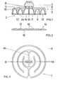
- Figur 1 zeigt einen Schnitt - parallel zur Sockelachse - durch eine aus schalenförmigem Oberteil und ebener Abschlußplatte bestehende Quecksilberdampf-Niederdruckentladungslampe in runder Ausführung (Sockelkörper ungeschnitten).
Figur 2 zeigt einen Schnitt - parallel zur Sockelachse - einer weiteren Ausführungsform der im wesentlichen ebenen Abschlußplatte.Figur 3 zeigt einen Grundriß des schalenförmigen Oberteils einer Quecksilberdampf-Niederdruckentladungslampe nach Figur 1.- Figur 4 zeigt einen Grundriß des schalenförmigen Oberteils einer Quecksilberdampf-Niederdruckentladungslampe in sechseckiger Ausführung.
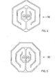
- Figur 5 zeigt einen Grundriß des schalenförmigen Oberteils einer Quecksilberdampf-Niederdruckentladungslampe in achteckiger Ausführung.
- FIG. 1 shows a section - parallel to the base axis - through a round version of a mercury vapor low-pressure discharge lamp consisting of a shell-shaped upper part and a flat end plate (base body uncut).
- Figure 2 shows a section - parallel to the base axis - of another embodiment of the substantially flat end plate.
- FIG. 3 shows a plan view of the bowl-shaped upper part of a mercury vapor low-pressure discharge lamp according to FIG. 1.
- FIG. 4 shows a plan view of the shell-shaped upper part of a low-pressure mercury vapor discharge lamp in a hexagonal design.
- FIG. 5 shows a plan view of the shell-shaped upper part of a low-pressure mercury vapor discharge lamp in an octagonal design.
Wie in Figur 1 dargestellt, setzt sich die erfindungsgemäße Lampe aus dem schalenförmigen Oberteil 1 und der im wesentlichen ebenen Abschlußplatte 2 zusammen. Das Oberteil 1 besitzt einen herabgezogenen Rand 3 sowie an seiner Innenseite Trennwände 4a, 4b, deren Symmetrieachsen senkrecht zur Deckfläche 5 verlaufen. Im Zentrum der Deckfläche 5 befindet sich ein Ansatz 6, der einen Sockel 7, z.B. einen Vierstiftsockel, trägt. Die Elektroden 8 sind gegenüber dem durch das schalenförmige Oberteil 1 und die Trennwände 4a, 4b gebildeten Entladungsweg 9 zurückgesetzt angeordnet. Die Innenseite 10 des schalenförmigen Oberteils 1 trägt über einer Schutzschicht aus Si02 eine dicke Leuchtstoffbeschichtung 11, die in einer Menge von 7 mg/cm2 aufgebracht ist. Diese Leuchtstoffbeschichtung 11 besteht zur Hälfte aus einem Ca-Halophosphat-Leuchtstoff, der mit Sb und Mn dotiert ist und zur anderen Hälfte aus einem Dreibanden-Leuchtstoffgemisch. Um eine Farbtemperatur von 2700 K zu erhalten, wie sie für Wohnraumbeleuchtung vorteilhaft ist, setzt sich das Dreibanden-Leuchtstoffgemisch aus 69,7 % mit Eu-dotiertem Yttriumoxid, 28,7 % mit Eu-dotiertem Ce-Mg-Aluminat und 1,6 % mit Eu-dotiertem Ba-Mg-Aluminat zusammen.As shown in FIG. 1, the lamp according to the invention is composed of the shell-shaped upper part 1 and the essentially
Die Abschlußplatte 2 ist auf ihrer der Entladung zugewandten Seite mit Nuten 12 zur Fixierung der Trennwände 4a, 4b und auf ihrer Außenseite mit einer Riffelung 13 versehen. Auf der Innenseite 14 befindet sich eine Schutzschicht aus Si0 2.The
Bei der in Figur 2 gezeigten weiteren Ausführungsform der Abschlußplatte 15 trägt diese auf ihrer der Entladung zugewandten Seite zwischen den Nuten 16 konvex ausgebildete Wölbungen 17. Auch bei dieser Ausführung ist eine Riffelung 18 vorgesehen.In the further embodiment of the
In Figur 3 ist der Grundriß des schalenförmigen Oberteils 1 - der Lampe nach Figur 1 - dargestellt. Dieser zeigt den gewundenen Entladungsweg 9, der durch die ringförmigen Trennwände 4a und die gerade Trennwand 4b gebildet wird. Innerhalb der,innersten ringförmigen Trennwand 4a sind zu beiden Seiten der geraden Trennwand 4b die Elektroden 8 angeordnet.In Figure 3, the plan of the bowl-shaped upper part 1 - the lamp of Figure 1 - is shown. This shows the
Figur 4 und 5 zeigen zwei weitere Ausführungsformen des schalenförmigen Oberteils der erfindungsgemäßen Lampe mit einem sechseckigen Umfang 19 und einem achteckigen Umfang 20. Die Anzahl der Ecken läßt sich beliebig erhöhen.FIGS. 4 and 5 show two further embodiments of the shell-shaped upper part of the lamp according to the invention with a
Das schalenförmige Oberteil und die ebene Abschlußplatte - entsprechend den Figuren 1 bis 5 - sind aus Preßglas gefertigt und mittels Glaslot miteinander verbunden.The bowl-shaped upper part and the flat end plate - corresponding to Figures 1 to 5 - are made of pressed glass and connected to each other by means of glass solder.
Die erfindungsgemäße Lampe weist vorzugsweise einen Durchmesser von 90 bis 120 mm auf. Die Höhe des schalenförmigen Oberteils (ohne Ansatzteil und Sockelkörper) liegt bei 20 bis 25 mm. Bei einem Außendurchmesser der Lampe von 100 mm und einer Leistungsaufnahme von 20 W sowie einer Betriebsspannung von 100 V läßt sich ein Lichtstrom von 1150 lm erreichen. Aufgrund der konstruktiven Eigenschaften, die die Lampe als Reflektorlampe wirken lassen, gelangt man zu einer Axiallichtstärke von 350 cd. Durch entsprechende Formgebung des Querschnitts des Entladungsweges kann dieser Wert für die Axiallichtstärke weiter erhöht werden.The lamp according to the invention preferably has a diameter of 90 to 120 mm. The height of the bowl-shaped upper part (without attachment part and base body) is 20 to 25 mm. With an outer diameter of the lamp of 100 mm and a power consumption of 20 W and an operating voltage of 100 V, a luminous flux of 1150 lm can be achieved. Because of The constructive properties that allow the lamp to act as a reflector lamp result in an axial light intensity of 350 cd. By appropriately shaping the cross section of the discharge path, this value for the axial light intensity can be increased further.
Claims (17)
Applications Claiming Priority (2)
| Application Number | Priority Date | Filing Date | Title |
|---|---|---|---|
| DE19813140839 DE3140839A1 (en) | 1981-10-14 | 1981-10-14 | FLAT-SHAPED MERCURY VAPOR LOW-PRESSURE DISCHARGE LAMP |
| DE3140839 | 1981-10-14 |
Publications (2)
| Publication Number | Publication Date |
|---|---|
| EP0077077A2 true EP0077077A2 (en) | 1983-04-20 |
| EP0077077A3 EP0077077A3 (en) | 1983-11-16 |
Family
ID=6144108
Family Applications (1)
| Application Number | Title | Priority Date | Filing Date |
|---|---|---|---|
| EP82109470A Withdrawn EP0077077A3 (en) | 1981-10-14 | 1982-10-13 | Panel-shaped low-pressure mercury vapour discharge lamp |
Country Status (3)
| Country | Link |
|---|---|
| EP (1) | EP0077077A3 (en) |
| JP (1) | JPS5875759A (en) |
| DE (1) | DE3140839A1 (en) |
Cited By (6)
| Publication number | Priority date | Publication date | Assignee | Title |
|---|---|---|---|---|
| EP0283014A2 (en) * | 1987-03-20 | 1988-09-21 | Sanyo Electric Co., Ltd. | Flat fluorescent lamp for liquid crystal display |
| US4920298A (en) * | 1987-03-20 | 1990-04-24 | Sanyo Electric Co., Ltd. | Flat fluorescent lamp for liquid crystal display |
| EP0389770A2 (en) * | 1989-03-31 | 1990-10-03 | Toshiba Lighting & Technology Corporation | Discharge Lamp |
| WO1992002947A1 (en) * | 1990-08-03 | 1992-02-20 | Lynn Judd B | Thin configuration flat form vacuum-sealed envelope |
| US5233262A (en) * | 1992-05-15 | 1993-08-03 | Judd B. Lynn | Flat form gas discharge lamp with optical reflecting means |
| WO2013017340A3 (en) * | 2011-07-29 | 2014-01-16 | Osram Gmbh | Illuminant with a protective layer and illuminant lamp comprising said illuminant |
Families Citing this family (3)
| Publication number | Priority date | Publication date | Assignee | Title |
|---|---|---|---|---|
| JPH01126050U (en) * | 1988-02-19 | 1989-08-29 | ||
| DE4232743A1 (en) * | 1992-09-30 | 1994-03-31 | Wolfgang Dipl Ing Topf | Energy-saving design for light source - has two or more oblong layers with recesses in mating surfaces that form internal gas discharge space |
| DE19600531A1 (en) * | 1995-12-29 | 1997-07-03 | Holzer Walter | Fluorescent lamp with replaceable light part |
Citations (5)
| Publication number | Priority date | Publication date | Assignee | Title |
|---|---|---|---|---|
| US2987640A (en) * | 1959-11-24 | 1961-06-06 | Gen Electric | Electric lamp envelope |
| FR1458494A (en) * | 1964-09-25 | 1966-03-04 | Dom Techniczno Handlowy | Electric discharge lamp |
| US3243630A (en) * | 1962-01-02 | 1966-03-29 | Gen Electric | Fluorescent panel lamp faceplate with opaque striping |
| US3611009A (en) * | 1969-06-17 | 1971-10-05 | William J Mcneil | Fluorescent light fixture |
| US3646383A (en) * | 1970-01-09 | 1972-02-29 | Gen Electric | Fluorescent panel lamp |
-
1981
- 1981-10-14 DE DE19813140839 patent/DE3140839A1/en not_active Withdrawn
-
1982
- 1982-10-12 JP JP17770282A patent/JPS5875759A/en active Pending
- 1982-10-13 EP EP82109470A patent/EP0077077A3/en not_active Withdrawn
Patent Citations (5)
| Publication number | Priority date | Publication date | Assignee | Title |
|---|---|---|---|---|
| US2987640A (en) * | 1959-11-24 | 1961-06-06 | Gen Electric | Electric lamp envelope |
| US3243630A (en) * | 1962-01-02 | 1966-03-29 | Gen Electric | Fluorescent panel lamp faceplate with opaque striping |
| FR1458494A (en) * | 1964-09-25 | 1966-03-04 | Dom Techniczno Handlowy | Electric discharge lamp |
| US3611009A (en) * | 1969-06-17 | 1971-10-05 | William J Mcneil | Fluorescent light fixture |
| US3646383A (en) * | 1970-01-09 | 1972-02-29 | Gen Electric | Fluorescent panel lamp |
Cited By (10)
| Publication number | Priority date | Publication date | Assignee | Title |
|---|---|---|---|---|
| EP0283014A2 (en) * | 1987-03-20 | 1988-09-21 | Sanyo Electric Co., Ltd. | Flat fluorescent lamp for liquid crystal display |
| US4920298A (en) * | 1987-03-20 | 1990-04-24 | Sanyo Electric Co., Ltd. | Flat fluorescent lamp for liquid crystal display |
| EP0283014A3 (en) * | 1987-03-20 | 1991-01-23 | Sanyo Electric Co., Ltd. | Flat fluorescent lamp for liquid crystal display |
| EP0389770A2 (en) * | 1989-03-31 | 1990-10-03 | Toshiba Lighting & Technology Corporation | Discharge Lamp |
| EP0389770A3 (en) * | 1989-03-31 | 1991-06-12 | Toshiba Lighting & Technology Corporation | Discharge lamp |
| WO1992002947A1 (en) * | 1990-08-03 | 1992-02-20 | Lynn Judd B | Thin configuration flat form vacuum-sealed envelope |
| US5233262A (en) * | 1992-05-15 | 1993-08-03 | Judd B. Lynn | Flat form gas discharge lamp with optical reflecting means |
| WO2013017340A3 (en) * | 2011-07-29 | 2014-01-16 | Osram Gmbh | Illuminant with a protective layer and illuminant lamp comprising said illuminant |
| CN103703099A (en) * | 2011-07-29 | 2014-04-02 | 欧司朗有限公司 | Illuminant and illuminant lamp comprising said illuminant |
| US9865449B2 (en) | 2011-07-29 | 2018-01-09 | Ledvance Gmbh | Illuminant and illuminant lamp comprising said illuminant |
Also Published As
| Publication number | Publication date |
|---|---|
| EP0077077A3 (en) | 1983-11-16 |
| DE3140839A1 (en) | 1983-04-21 |
| JPS5875759A (en) | 1983-05-07 |
Similar Documents
| Publication | Publication Date | Title |
|---|---|---|
| DE2835574C2 (en) | ||
| DE69630068T2 (en) | Fluorescent Lamp | |
| DE2904864C2 (en) | ||
| EP0201926B1 (en) | Indirect mirror light fixture | |
| DE2906383C2 (en) | High pressure sodium vapor discharge lamp | |
| DE3005017A1 (en) | ELECTRIC LAMP UNIT | |
| DE4132530A1 (en) | HIGH PRESSURE DISCHARGE LAMP WITH LOW POWER | |
| DE3506295A1 (en) | COMPACT HIGH PRESSURE DISCHARGE LAMP | |
| DE19963278A1 (en) | Compact discharge fluorescent lamp with cut-in unit, has connecting tube including individual supply wire in auxiliary amalgam in sealing section | |
| DE3027536A1 (en) | LOW PRESSURE MERCURY STEAM DISCHARGE LAMP | |
| EP0077077A2 (en) | Panel-shaped low-pressure mercury vapour discharge lamp | |
| EP0706713B1 (en) | Metal halide high-pressure discharge lamp | |
| DE19844164B4 (en) | Energy saving lamps with film reflecting in the infrared | |
| DE3021517A1 (en) | COMPACT LOW-PRESSURE DISCHARGE LAMP WITH SPLIT PISTON | |
| EP1589563A2 (en) | Dielectric barrier discharge lamp with external electrodes and lighting system with this lamp | |
| DE3736922C2 (en) | ||
| DE19919363A1 (en) | Discharge lamp with spacer | |
| DE3106721A1 (en) | "LOW PRESSURE DISCHARGE LAMP" | |
| DE889806C (en) | Light source for irradiation, lighting, headlights and projection | |
| EP0697136B1 (en) | Compact fluorescent light bulb | |
| EP0274107A2 (en) | Electric lamp | |
| DE1489406B2 (en) | HIGH PRESSURE MERCURY VAPOR DISCHARGE LAMP | |
| DE2709221A1 (en) | MIRROR CONDENSER LAMP | |
| EP0926704A1 (en) | Flat signalling lamp with dielectric barrier discharge | |
| DE4312743A1 (en) | Cylindrical compact fluorescent lamp |
Legal Events
| Date | Code | Title | Description |
|---|---|---|---|
| PUAI | Public reference made under article 153(3) epc to a published international application that has entered the european phase |
Free format text: ORIGINAL CODE: 0009012 |
|
| AK | Designated contracting states |
Designated state(s): DE FR GB IT |
|
| PUAL | Search report despatched |
Free format text: ORIGINAL CODE: 0009013 |
|
| AK | Designated contracting states |
Designated state(s): DE FR GB IT |
|
| 17P | Request for examination filed |
Effective date: 19840410 |
|
| STAA | Information on the status of an ep patent application or granted ep patent |
Free format text: STATUS: THE APPLICATION HAS BEEN WITHDRAWN |
|
| 18W | Application withdrawn |
Withdrawal date: 19851122 |
|
| RIN1 | Information on inventor provided before grant (corrected) |
Inventor name: STEEGER, GERHARD, DR. Inventor name: SCHIPP, FRITZ, DR. DIPL.-PHYS. |