EP0077073B1 - Electrode électro-chimique et procédé de mesure transcutanée d'un paramètre sanguin - Google Patents
Electrode électro-chimique et procédé de mesure transcutanée d'un paramètre sanguin Download PDFInfo
- Publication number
- EP0077073B1 EP0077073B1 EP82109436A EP82109436A EP0077073B1 EP 0077073 B1 EP0077073 B1 EP 0077073B1 EP 82109436 A EP82109436 A EP 82109436A EP 82109436 A EP82109436 A EP 82109436A EP 0077073 B1 EP0077073 B1 EP 0077073B1
- Authority
- EP
- European Patent Office
- Prior art keywords
- electrode device
- jacket
- measuring electrode
- electrochemical measuring
- temperature
- Prior art date
- Legal status (The legal status is an assumption and is not a legal conclusion. Google has not performed a legal analysis and makes no representation as to the accuracy of the status listed.)
- Expired
Links
Images


Classifications
-
- G—PHYSICS
- G01—MEASURING; TESTING
- G01K—MEASURING TEMPERATURE; MEASURING QUANTITY OF HEAT; THERMALLY-SENSITIVE ELEMENTS NOT OTHERWISE PROVIDED FOR
- G01K1/00—Details of thermometers not specially adapted for particular types of thermometer
- G01K1/16—Special arrangements for conducting heat from the object to the sensitive element
-
- A—HUMAN NECESSITIES
- A61—MEDICAL OR VETERINARY SCIENCE; HYGIENE
- A61B—DIAGNOSIS; SURGERY; IDENTIFICATION
- A61B5/00—Measuring for diagnostic purposes; Identification of persons
- A61B5/145—Measuring characteristics of blood in vivo, e.g. gas concentration, pH value; Measuring characteristics of body fluids or tissues, e.g. interstitial fluid, cerebral tissue
- A61B5/14542—Measuring characteristics of blood in vivo, e.g. gas concentration, pH value; Measuring characteristics of body fluids or tissues, e.g. interstitial fluid, cerebral tissue for measuring blood gases
-
- A—HUMAN NECESSITIES
- A61—MEDICAL OR VETERINARY SCIENCE; HYGIENE
- A61B—DIAGNOSIS; SURGERY; IDENTIFICATION
- A61B5/00—Measuring for diagnostic purposes; Identification of persons
- A61B5/145—Measuring characteristics of blood in vivo, e.g. gas concentration, pH value; Measuring characteristics of body fluids or tissues, e.g. interstitial fluid, cerebral tissue
- A61B5/1468—Measuring characteristics of blood in vivo, e.g. gas concentration, pH value; Measuring characteristics of body fluids or tissues, e.g. interstitial fluid, cerebral tissue using chemical or electrochemical methods, e.g. by polarographic means
- A61B5/1477—Measuring characteristics of blood in vivo, e.g. gas concentration, pH value; Measuring characteristics of body fluids or tissues, e.g. interstitial fluid, cerebral tissue using chemical or electrochemical methods, e.g. by polarographic means non-invasive
-
- A—HUMAN NECESSITIES
- A61—MEDICAL OR VETERINARY SCIENCE; HYGIENE
- A61B—DIAGNOSIS; SURGERY; IDENTIFICATION
- A61B5/00—Measuring for diagnostic purposes; Identification of persons
- A61B5/145—Measuring characteristics of blood in vivo, e.g. gas concentration, pH value; Measuring characteristics of body fluids or tissues, e.g. interstitial fluid, cerebral tissue
- A61B5/1491—Heated applicators
-
- G—PHYSICS
- G01—MEASURING; TESTING
- G01K—MEASURING TEMPERATURE; MEASURING QUANTITY OF HEAT; THERMALLY-SENSITIVE ELEMENTS NOT OTHERWISE PROVIDED FOR
- G01K1/00—Details of thermometers not specially adapted for particular types of thermometer
- G01K1/16—Special arrangements for conducting heat from the object to the sensitive element
- G01K1/165—Special arrangements for conducting heat from the object to the sensitive element for application in zero heat flux sensors
-
- G—PHYSICS
- G01—MEASURING; TESTING
- G01K—MEASURING TEMPERATURE; MEASURING QUANTITY OF HEAT; THERMALLY-SENSITIVE ELEMENTS NOT OTHERWISE PROVIDED FOR
- G01K1/00—Details of thermometers not specially adapted for particular types of thermometer
- G01K1/20—Compensating for effects of temperature changes other than those to be measured, e.g. changes in ambient temperature
Definitions
- the present invention relates to electrochemical measuring electrode devices for transcutaneous measurement of a blood parameter such as the partial pressure of a blood gas according to the generic clause of claim 1.
- the transcutaneous measuring technique is well-known in the art.
- an electrode device for measuring the blood parameter in question is applied to a skin surface of a person in whom the blood parameter is to be measured.
- the electrode device is thermostated to a predetermined temperature, normally (when the blood parameter to be measured is, e.g., the partial pressure of a blood gas such as oxygen) a temperature above normal skin temperature so as to cause local hyperemia in the skin surface in contact with the electrode.
- parameters measured transcutaneously e.g. blood gas partial pressures
- the corresponding arterial values which are the values normally used for clinical purposes.
- the parameters measured transcutaneously can no longer be considered as reflecting the arterial values.
- Reference 2 suggests a device where the heat exchange with the surroundings is limited by means of a heat shell over the electrode device, the heat shell being circulated with water at electrode temperature, but reports that only about 30% of the heat transferred from the electrode to the skin is flow related.
- Reference 3 suggests a combined O l /CO 2 and flow sensor which is adapted to be mounted on the forearm of a test person.
- a second servo-controlled heater/thermistor is included and arranged in heat-conductive contact with a second heater assembly arranged on the outside of the sensor.
- the second servo-controlled heater/thermistor is adapted to maintain the temperature of the second heater assembly at a temperature of 0.5°C below the temperature of the first heater assembly.
- the senor When employed in conjunction with an occlusive system which is adapted to be arranged enclosing the entire forearm of a test person or patient and, furthermore, increases the insulation properties, the sensor is reported to be able to register a perfusion-dependent heat transfer to the skin of approximately 50% of the total sensor power.
- the invention provides an electrochemical measuring electrode device having the features of claim 1.
- the spaced heat-insulating relationship between said body and said jacket will be such that a substantially narrow space is defined between the outer periphery of said body and the adjacent inner surface of said jacket.
- the jacket may, in principle, be heated to a temperature which is different from the temperature of the body, but it is generally preferred that the body and the jacket are adapted to be heated to the same temperature so as to obtain a zero heat flux between said two bodies.
- the construction will normally be most suitable when the body has a substantially circular cylindrical shape, and the jacket will then suitably have a substantially annular wall part which is arranged coaxially relative to said body.
- the thermostating time constant and the thermal time constant of the body should both be low.
- the thermostating time constant (related to the active, heating function of the body) should be as low as possible to permit the system to respond immediately to power transport from the body and maintain a constant temperature.
- the thermostating time constant is proportional to the heating resistance of the system constituted by the body and the heating means heating the body, and hence, the effective heat-conductive contact between the body and the heating means of the first thermostating means should be as high as possible.
- the thermal time constant (related to the passive, cooling function) should be low to permit the system to immediately sense a higher power consumption by the blood flow.
- the thermal time constant will be proportional to the thermal capacity of the body, which means that in order to obtain a low thermal capacity, the volume of the body should be as small as possible. At the same time, the heat-conductive contact area between the body and the skin surface should be as large as possible. All of these considerations are best fulfilled when the body is disc-shaped, allowing for an optimum heat-conductive contact between the heating means of the first thermostating means and for the smallest possible volume at a given heat-conductive skin contact area.
- the first thermostating means may, in principle, comprise any combination of heating means and temperature sensing means which will be suitable for the purpose in view of the above considerations.
- One combination which has been found suitable in practice comprises an NTC-resistor and a heating resistor.
- a compact and flat construction is obtainable when said first thermostating means is arranged on a first thick film substrate, and according to a preferred embodiment of the invention, the first thermostating means is constructed as thick film components on said first thick film substrate, the said thick film substrate preferably constituting said body.
- this thick film substrate preferably has a plane or plane-convex shape.
- the thick film substrate will preferably have a thickness of about 0.2-1.5 mm, in particular about 0.3-0.8 mm.
- the diameter of the thick film substrate will normally be about 5-12 mm.
- Thick film substrates which are especially suitable for the purpose of the invention because of their favourable combination of electrically insulating properties and specific heat capacity properties are thick film substrates made of alumina or beryllia.
- the body may also be made using thin film technology.
- the sensor means and the thermostating means will normally be applied on the body by means of thin film technique.
- the thin film substrate may, e.g. be made of ceramic material such as alumina or beryllia, or of silicon.
- the dimensions of the body may be the same as stated above for thick film bodies, but the thin film technique also permits the use of thinner and/or smaller bodies, optionally with several sensors applied on one and the same body.
- the thermostating time constant of the jacket should be as low as possible in order to permit the jacketto respond as fastas possible in thermostating.
- the thermal time constant of the jacket relating to passive cooling of the jacket should be as high as possible.
- the jacket may be made from any material showing suitable specific heat capacity for the purpose, e.g. a metal such as copper or silver.
- the thermostating means thermostating the jacket may suitably comprise similar components as the thermostating means thermostating the body.
- this second thermostating means suitably comprises an NTC-resistor and a heating resistor and is suitably arranged on a thick film substrate in heat-conductive connection with the jacket.
- this second thermostating means is suitably constructed as thick film components on said thick film substrate, which suitably is a circular substrate that preferably has a plane or plane-convex shape. Also this substrate is preferably made of alumina or beryllia.
- the thermal resistance between the body and the jacket should be sufficiently high to substantially eliminate thermal crosstalk between the body and the jacket.
- the thermal resistance between said jacket and said body should preferably be at least one order of magnitude (power of 10) greater than the thermal resistance between the body and the capillary bed beneath the skin surface.
- power of 10 the thermal resistance between the body and the capillary bed beneath the skin surface.
- the sensor means of the electrochemical measuring electrode device may be sensor means adapted for measurement of any blood parameter which can be measured by means of an electrochemical measuring electrode, e.g., pH or the partial pressure of a blood gas.
- the sensor means may be of any suitable type adapted to be included in the selected type of body. Examples of sensor means suitable for the present purpose appear, e.g., from Danish Patent Application No. 1650/81 and 1676/81, both in the name of Radiometer A/S and may, e.g., comprise sensor means for measuring the partial pressure of oxygen and/or carbon dioxide.
- the sensor means When the sensor means are adapted for the measurement of the partial pressure of oxygen, they may suitably comprise a cathode of a noble metal-capable of electrochemical reduction of oxygen, and an anode cooperating with said cathode and preferably being a silver anode.
- the device according to the invention will normally comprise a membrane and an electrolyte solution, said membrane being arranged adjacent to said surface part of said body so as to define a space wherein said electrolyte solution is confined.
- the invention also relates to a method for transcutaneous measurement of a blood parameter, said method comprising the features, of claim 25.
- the measurement of the blood parameter in question is performed in the normal manner, suitably utilizing normal amplifying and/or recording means.
- the body and the jacket are preferably thermostated to the sametemperature to obtain a zero heat flux therebetween.
- the power eliminated by perfusion below the electrode may be expressed in the following manner: wherein Q is the power being eliminated, F is the blood flow, C is the heat capacity of the blood, AT is the temperature increase of the blood, i.e. the difference between the capillary temperature, T c , and the arterial temperature or the deep body temperature, T DBT , and A is the area of the electrode device.
- Q is the power being eliminated
- F is the blood flow
- C the heat capacity of the blood
- AT is the temperature increase of the blood, i.e. the difference between the capillary temperature, T c , and the arterial temperature or the deep body temperature, T DBT
- A is the area of the electrode device.
- Q may be measured by measuring the power, P F , before occlusion and by measuring the power, P u , during occlusion, since
- T c may be calculated from the electrode temperature, T E , from P F , and the thermal resistance, R, from the electrode to the capillary tissue, since which may be rearranged into
- P u i.e. the power generated during occlusion
- F may be registered continuously.
- the above described method for measuring the blood flow, F does, however, suffer from one major drawback since the measuring result may be affected by a change in deep body temperature, T DBT .
- T DBT deep body temperature
- Such a change in deep body temperature may cause a major change of the power, Q, being eliminated and, consequently, a major change of the actual measuring result of the blood flow.
- T DBT deep body temperature
- a probe for carrying out the measuring method comprises two thermistors arranged on top of one another within a jacket-shaped encasing of a heat-conductive material which is provided with heating means.
- the upper thermistor is arranged in heat-conductive contact with the jacket-shaped encasing which is adapted to be arranged in contact with the skin surface of a test person or a patient so that the lower thermistor arranged within the encasing is also arranged in contact with the skin surface.
- the deep body temperature, TDBT ' may be measured by controlling the heating of the encasing in such a manner that the temperature difference between the two thermistors becomes zero, i.e. so that the heat flow across the probe is zero.
- T oBT the temperature determined by any of said two thermistors equilibrates the deep body temperature, T oBT .
- the above mentioned deep body temperature measuring method may also be carried out by means of the electrochemical measuring electrode device according to the invention.
- the electrochemical measuring electrode device according to the invention is, in an alternative operational mode, adapted to carry out the said measuring method and, thus, in a very elegant way provide deep body temperature measuring results for the above described blood flow measuring method.
- the jacket is thermostated to such a temperature that the temperature registered by the temperature sensing means of said first thermostating means and the temperature registered by the temperature sensing means of said second thermostating means are identical to one another and, consequently, identical to the deep body temperature, T DBT .
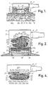
- a first embodiment of an electrochemical measuring electrode device is shown in which the main components of the electrode device are shown.
- the measuring electrode device designated 1 in its entity is located at a skin surface shown schematically in Fig. 1 and designated 2.
- the electrode device 1 comprises an electrode housing 3 made of plastics, e.g. acrylonitrile-butadiene-styrene.
- the electrode housing 3 is connected to a metallic body 4 of material showing high heat conductivity, e.g. copper, the importance of which will be explained in greater detail below.
- the electrode device comprises an annular body 5 also made of plastics, e.g. acrylonitrile-butadiene-styrene.
- the electrode housing 3 is provided with a stub 6 adapted to cooperate with a multicore cable 7 the ' jacket of which is shown in Fig. 1 and which is adapted to connect the electrode device to external measuring equipment.
- a thick film substrate 8 of e.g. alumina, is located in thermal conductive connection therewith.
- the substrate 8 is provided with thermostating means, i.e. temperature measuring means and temperature controlling means, e.g. an NTC-resistor and a heating resistor which may be constructed in thick film technique on the substrate or provided as discrete components as will be described in greater detail below.
- the electrode housing 3 is provided with a cover, not shown, opposite to the metallic body 4 and the thick film substrate 8.
- the interior space thus defined in the electrode housing 3 is filled up with an appropriate filling material or casting, e.g. an epoxy casting.
- a thick film substrate 10 of e.g. alumina which constitutes the sensor substrate in the inventive measuring electrode device in accordance with the principles described in Applicant's copending Danish patent applications No. 1650/81.
- the substrate 10 being a substantially circular substrate has a substantially plane upper surface as the substrate 8, which is a substantially circular substrate having two opposite plane surfaces, and a domed lower surface provided with a central protrusion 10a.
- the substrates 8 and 10 may be identical, i.e. of the above described type having a plane and a domed surface provided with a central protrusion.
- the inner space defined within the annular body 5 between the lower surface of the metallic body 4 and the upper surface of the substrate 10 is also filled with an appropriate filling material or casting, e.g. an epoxy casting.
- an appropriate filling material or casting e.g. an epoxy casting.
- the embodiment of the invention shown in Fig. 1 is a polarographic electrode device comprising an anode layer 11 and a cathode (not shown) arranged in a through-going passage in the central protrusion 10a of the sensor substrate 10 in a manner described in applicant's copending Danish patent application No. 1650/81. Furthermore, the anode layer 11 being a thick film silver layer is connected to a terminal field on the opposite side of the substrate 10 by means of a leading through connection in a manner also described in applicant's above mentioned Danish patent applications.
- an 0-ring 13 is located which secures a gas permeable and liquid impermeable membrane 14 relative to the lower domed surface of the sensor substrate 10.
- the membrane 14 may be made of e.g. polypropylene or tetrafluoroethylene.
- the above mentioned central protrusion 10a of the sensor substrate 10 provides, in combination with the membrane 14, an electrolyte reservoir 15 for an electrolyte solution of the electrochemical measuring electrode device.
- the metallic body 4 is provided with external threads which are adapted to cooperate with corresponding internal threads of an annular metallic body 16, preferably also made of a material showing high heat conductivity, e.g. copper.
- the metallic body 16 is thermally connected to the substrate 8 through the metallic body 4.
- the two metallic bodies 4 and 16 constitute a metallic jacket enclosing the sensor substrate of the electrode device.
- the jacket and the sensor substrate are adapted to be thermostated by means of the thermostating means on the substrate 8 and the thermostating means on the substrate 10, respectively.
- the annular metallic body 16 is mounted within an annular fixing ring 17 made of a material showing excellent thermal insulating qualities, e.g. plastics including acrylontrile-butadiene-styrene.
- the sensor substrate 10 and thus the active surface of the electrochemical measuring electrode device and the jacket, i.e. the substrate 8 arranged in heat conductive connection with the metallic body 4 and the annular metallic body 16 are thermostatically heated to the same temperature, e.g. 45°C.
- the heating of the sensor substrate 10 and the jacket to the same temperature provides that there is substantially no net heat flow between the sensor substrate 10 and the jacket. Therefore, the heat flux from the sensor substrate 10 is unidirectional, i.e. has a downward direction to the skin surface below the active sensor surface of the sensor substrate.
- the jacket Apart from virtually insulating the sensor substrate 10 totally relative to the environment, the jacket also contributes to the heating of the skin surface belowthe electrode device in such a manner that any heat flux from the sensor substrate 10 to any part of the skin surface outside the jacket dimensions are virtually eliminated. Therefore, the jacket provides a virtual heat jacket in relation to the skin surface heated by the sensor substrate 10 so that the heat flow from the sensor substrate 10 apartfrom being unidirectional becomes virtually one-dimensional.
- This aspect is illustrated in Fig. 1 by a curve 18 (a, b, c) which is shown indicating an isoterm, i.e. a curve drawn through locations having identical temperature. As will be seen from Fig.
- the width of the uniformly heated skin surface is largely increased as indicated by the outer branches of the curve (18a, 18b) relative to the situation in which only the sensor surface, i.e. the substrate 10, is thermostatically heated to a temperature above skin temperature (18c).
- This largely increased and uniformly heated skin surface in which hyperemia is produced and which is obtained by means of the annular metallic body 16 in heat conductive connection with the substrate 8 being thermostatically heated to the same temperature as the sensor substrate 10, provides the excellent measuring results which may be obtained by means of the electrochemical measuring electrode device according to the invention as will be described in greater detail below.
- a second embodiment of the electrochemical measuring electrode device according to the invention is shown.
- the embodiment shown in Fig. 2 differs only slightly from the embodiment shown in Fig. 1 and therefore, identical reference numerals are being used for identical parts.
- the electrode housing 3 is provided with the protruding annular part designated 3a
- the annular fixing ring 17 is provided with a covering part 17a which covers the annular metallic body 16 which is mounted within the fixing ring 17.
- the said annular metallic body 16 is provided with an internal annular recess in which a thermally insulating ring body 19 is located, which is made of e.g. plastics including acrylonitrile-butadiene-styrene.
- plastics including acrylonitrile-butadiene-styrene.
- FIG. 2 several individual cores 20a, 20b, 20c, 22a, 22b, 22c, 22d and 22e of the multicore cable 7 are shown of which the cores 20a, 20b, and 20c are connected to the components on the substrate 8 through soldered joints 21 a, 21 b, and 21 c, respectively.
- the cores 22a, 22b, 22c, 22d, and 22e are led through an aperture in the substrate 8 and an aperture in the metallic body 4 and connected to components on the substrate 10 through soldered joints 23a, 23b, 23c, 23d, and 23e, respectively.
- Fig. 3 an exploded view of the above described second embodiment of the electrochemical measuring electrode device according to the invention is shown.
- a cover 24 is shown which has been mentioned above but which is not shown in Figs. 1 or 2.
- the multicore cable 7, the electrode housing 3, the substrate 8, the metallic body 4, the annular body 5, the substrate 10, and the annular fixing ring 17 are shown.
- the substrates 8 and 10 are shown in greater detail compared to Figs. 1 and 2.
- the thermostating means i.e. the temperature measuring means and the temperature controlling means of the substrates 8 and 10 are shown.
- an NTC-resistor 25 and a heating resistor 26 are applied in thick film technique.
- the substrate 10 is provided with an NTC-resistor 27 and a heating resistor 28 and, furthermore, a terminal field 29 for connection to an electrode of the sensor substrate and the electrochemical measuring electrode device.
- NTC-resistor 27 and a heating resistor 28
- terminal field 29 for connection to an electrode of the sensor substrate and the electrochemical measuring electrode device.
- the embodiment of the electrochemical measuring electrode device according to the invention i.e. the embodiments shown in Fig. 1 and in Figs. 2 and 3, respectively, are adapted to be mounted within the annular fixing ring 17, the embodiment of the invention shown in Fig. 4 is adapted to be mounted within a conventional fixing ring. Therefore, the electrode housing 3, the metallic body 4, the annular body 5, the annular metallic body 16, shown in Figs. 1-3, are omitted in Fig. 4 and replaced by alternative components in order to permit mounting of the electrode device shown in Fig. 4 in the said conventional fixing ring.
- a funnel-shaped metallic body or jacket 30 which is mounted within an electrode housing 31 which constitutes both the components 3 and 5 shown in Figs. 1-3. Furthermore, the embodiment shown in Fig. 4 comprises an annular body 32 which is mounted within an internal recess in the funnel-shaped metallic body 30 and in a recess of which the sensor substrate 10 is mounted.
- the above mentioned cores 20a, 20b, 20c, 22a, 22b, 22c, 22d, and 22e and the above mentioned corresponding soldered joints 21 a, 21 b, 21 c, 23a, 23b, 23c, 23d, and 23e a fourth core 20d and a corresponding soldered joint 21 d of a component on the substrate 8 are shown in Fig. 4.
- the funnel-shaped metallic body 30 and the substrate 8 may be replaced by a single funnel-shaped body made of e.g. alumina which constitutes the jacket of the electrochemical measuring electrode device.
- the funnel-shaped body may be provided with a thick film component constructed on the substrate 8 in the embodiment shown in Fig. 4.
- Fig. 5 a fourth embodiment of an electrochemical measuring electrode device according to the invention is shown.
- the embodiment shown in Fig. 5 differs from the embodiment shown in Fig. 4 in that the total size or height of the electrode device including the fixing ring is reduced radically. This is obtained by integration of the electrode housing and the fixing ring.
- the funnel-shaped metallic body or jacket 30 is mounted in a recess in a funnel-shaped body 33 also constituting the cover of the electrode device.
- the funnel-shaped body 33 may be made of e.g. acrylonitrile-butadiene-styrene.
- the funnel-shaped body 33 is provided with a circumferential groove which is adapted to cooperate, in a spring catch, with an internal annular protrusion of a ring 34 which is also provided with an external annular protrusion adapted to cooperate, in another spring catch, with a corresponding circumferential groove in a fixing ring 35 of conventional shape.
- the ring 34 and the fixing ring 35 are preferably made of plasticized polyvinyl chloride and polypropylene, respectively.
- the annular body 32 In the funnel-shaped metallic body 30 the annular body 32, also shown in Fig. 4, is mounted. Within the above mentioned recess in the annular body 32, the sensor substrate 10 is mounted.
- the electrode device shown in Fig. 5 also comprises a membrane 36 which is secured to the ring 34 in an appropriate manner, e.g. by welding. In conjunction with the central protrusion 10a of the sensor substrate 10 and the anode layer 11, the membrane 36 provides the above described reservoir 15 for the electrolyte solution of the electrode device.
- the stub 6 and the multicore cable 7 have an elliptical shape which also contributes to the overall reduction of the height of the electrode device.
- FIGs. 6 and 7 two alternative embodiments of an electrochemical measuring electrode device according to the invention are shown.
- the embodiments of the invention hitherto described employ mechanical fixing of the electrode housing relative to the fixing ring.
- magnetic fixing is employed.
- the metallic body 4 shown in Fig. 2 is replaced by a magnetic body 37.
- the annular metallic body 16 shown in Fig. 2 is replaced by an annular magnetic body 38 showing high heat conductivity.
- the magnetic body 37 has a frusto-conical shape and the annular magnetic body 38 has a conical upper surface adapted to fit and cooperate with the conical surface of the frusto-conical shape of the magnetic body 37.
- the magnetic body 37 and the annular magnetic body 38 are magnetized having opposite magnetic poles facing one another.
- the magnetic body 37 and the annular magnetic body 38 are preferably made of an AINiCo-material known as CROVAC O or a CoRe-based material known as VACOMAX ⁇ , and together constitute the jacket of the embodiment.
- the above described magnetic fixing means comprising the magnetic body 37 and the annular magnetic body 38 shown in Fig. 6 are replaced by metallic plate 39 of a material showing high heat conductivity, such as copper, together with a magnetic ring 40, and an annular metallic body of a material showing high heat conductivity, such as copper, together with an annular magnetic body 42, respectively.
- the metallic plate 39 is mounted in thermal conductive connection with the substrate 8 in the electrode housing 3 together with the magnetic ring 40.
- the annular metallic body 41 and the annular magnetic body 42 are mounted within the fixing ring 17.
- the magnetic ring 40 and the annular magnetic body 42 are magnetized having opposite magnetic poles facing one another.
- the magnetic ring 40 and the annular magnetic body 42 are preferably also made of CROVAC or VACOMAX and adapted to cooperate in such a manner that the metallic plate 39 and the annular metallic body 41 are brought into thermal conductive connection when said magnetic means are fitted together so as to form the jacket.
- Figs. 8-12 illustrate results which may be obtained by means of the electrochemical measuring electrode device according to the invention.
- Fig. 8 two curves are shown, one in dotted line and one in solid line showing results obtained by means of a conventional transcutaneous oxygen measuring electrode device and an electrochemical measuring electrode device of the kind shown in Fig. 2, respectively.
- the conventional electrode device (Radiometer E 5240 from Radiometer A/S, Copenhagen) comprised a silver body of diameter about 6 mm thermostated by means of an NTC resistor and a zener diode.
- This conventional electrode contained no thermostated jacket around the body, the body was cast into a housing of ABS with a diameter of about 20 mm with epoxy casting between the body and the housing.
- the electrode device of the kind shown in Fig. 2 had a sensor body 10 made of alumina and having a thickness of 0.635 mm and a diameter of 10.5 mm.
- the thermostating means comprised a discrete NTC resistor and a heating resistor applied on the substrate in thick film technique.
- the distance between the outer periphery of the sensor body and the adjacent inner surface of the jacket 16 was 2 mm, and the distance between the lower surface of the jacket and the upper surface of the body was 3 mm.
- the jacket consisted of copper, and the upper substrate 8 was of alumina.
- the outer diameter of the jacket was 16 mm.
- the space between the body 10 and the jacket was filled with epoxy casting material (Scotchcast° 250).
- the housing 3 and the annular fixing ring 17 were made of ABS.
- the curves represent the power supplied to the body heating elements of the electrode devices to keep the body temperature at 45°C under various tests conditions, plotted versus time.
- the abscissa is divided into sections A, B, C, D, E, F, and G, respectively, corresponding to the periods of time of the various test conditions mentioned above.
- the change of power at occlusion constitutes only 16.7% in the conventional electrochemical measuring electrode device while the change of power under the same test conditions constitutes 50% in the electrode device according to the invention.
- the sensitivity to ambient changes is greatly reduced in the electrode device according to the invention.
- the annular metallic body 16 of the jacket was removed. Relative to the results described above, the power generated by the body of the electrode device, i.e. generated by the heating means of the sensor substrate 10, was increased by approximately 80% in steady state. In a further alternative experiment the jacket was disconnected and, consequently, the power generated by the body of the electrode device rose approximately 150% relative to the result described above, i.e. when employing the jacket according to the principles of the present invention.
- Fig. 9 an essential advantage of a thick film body compared to a conventional body is illustrated.
- the conventional electrode device and the electrode device of the invention were the same as described in connection with Fig. 8.
- the two devices were arranged face to face at a distance of 3 cm from each other in still air at 25°C. 600 mW was supplied to the body heating means of each electrode device, the thermostating temperature of each body being preset at 43°C.
- the temperature response of each device was measured by means of its body thermostating temperature sensor. Two curves are shown, one in dotted line and one in solid line, showing the temperature response of the conventional electrode device and the electrode device according to the invention, respectively.
- the initial response -of the electrode device according to the invention is greatly improved, since the rise time is reduced, and the overshoot of the conventional electrode device is almost completely eliminated in the electrochemical measuring electrode device according to the invention.
- the decay time of the electrochemical measuring electrode device according to the invention is reduced compared to the conventional electrochemical measuring electrode device as indicated at H in Fig. 9. Therefore, the electrochemical measuring electrode device according to the invention with a thick film substrate constituting the body responds far more rapidly to temperature changes induced, and, of particular importance in the present context, will respond more rapidly to temperature changes induced in consequence of variations in the blood flow.
- Fig. 10 two curves are shown, one in dot-and-dash-line, and one in solid line.
- the dot-and-dash lined curve and the solid line curve illustrate the power supplied to the electrochemical measuring electrode device according to the invention (the device described in connection with Fig. 8 above) when measuring on a forearm of a test person and a signal indicating the partial pressure of oxygen at the application site of said test person, respectively.
- the curves After the period of stabilization, indicated as the period I, the curves reach steady state as indicated in the period J, whereupon a cuff is applied to the forearm of the test person during the period K. Thereafter, the blood flow is occluded and the curves show simultaneous decreases during the period L. The decrease in power generated in the electrode device make up approximately 50%. After the occlusion, the curves reach during the period M the same steady state values as in the period J.
- Fig. 11 a diagram is shown illustrating blood flow measuring results obtained by means of the electrochemical measuring electrode device according to the invention and blood flow measuring results obtained simultaneously by a y-emission counting method.
- a dose of Xe-133 is implanted transcutaneously, and the depletion of Xe-133 is measured by counting the y-emission decay by means of a scintillation-counter arranged above the implantion site.
- Measuring results obtained simultaneously by counting the y-emission (X) and by means of the electrochemical measuring electrode device according to the invention in accordance with the blood flow measuring method described above (Y) are indicated by circles and dots referring to two different test persons.
- the measuring results obtained by means of the electrochemical electrode device according to the invention were corrected relative to drift caused by occlusion and recalculated into volume blood flow results by multiplying the measuring results obtained by a factor referring to skin thickness.
- Linear regression was carried out, and correlation coefficients were calculated. The line of regression, indicating an almost perfect agreement between the measuring results obtained in accordance with the two different measuring methods is shown in Fig. 11.
- Fig. 12 a diagram is shown illustrating measuring results obtained in an experiment.
- the electrochemical measuring electrode device according to the invention was adapted to measure deep body temperature simulated by a water bath having a predetermined temperature.
- the electrode device was arranged in a boat measuring 80 X 120 mm and made of polyvinylchloride, PVC, of a thickness of 1.3 mm.
- the polyvinylchloride layer of a thickness of 1.3 mm corresponds thermally to a skin thickness of approximately 3 mm.
- the annular jacket is heated in such a manner controlled by the temperature sensing means of the electrode body that any temperature difference between the temperature measured by the temperature sensing means of the body and the temperature measured by the temperature sensing means of the jacket is substantially eliminated.
- the temperature of the water bath is altered and monitored by means of a calibrated thermometer. The temperature measured by the temperature sensing means of the electrode body was recorded and the measuring results thus obtained are indicated in the table below:
- T DBTr provides exact measuring results within the temperature range 35°C-45°C. The measuring results are not affected by the environmental temperature which was approximately 25°C.
Claims (28)
Applications Claiming Priority (2)
| Application Number | Priority Date | Filing Date | Title |
|---|---|---|---|
| DK454681 | 1981-10-13 | ||
| DK4546/81 | 1981-10-14 |
Publications (3)
| Publication Number | Publication Date |
|---|---|
| EP0077073A2 EP0077073A2 (fr) | 1983-04-20 |
| EP0077073A3 EP0077073A3 (en) | 1985-10-23 |
| EP0077073B1 true EP0077073B1 (fr) | 1989-08-09 |
Family
ID=8134512
Family Applications (1)
| Application Number | Title | Priority Date | Filing Date |
|---|---|---|---|
| EP82109436A Expired EP0077073B1 (fr) | 1981-10-13 | 1982-10-12 | Electrode électro-chimique et procédé de mesure transcutanée d'un paramètre sanguin |
Country Status (7)
| Country | Link |
|---|---|
| US (1) | US4539994A (fr) |
| EP (1) | EP0077073B1 (fr) |
| JP (1) | JPS58501659A (fr) |
| AT (1) | ATE45278T1 (fr) |
| DE (1) | DE3279860D1 (fr) |
| DK (1) | DK150843C (fr) |
| WO (1) | WO1983001510A1 (fr) |
Cited By (1)
| Publication number | Priority date | Publication date | Assignee | Title |
|---|---|---|---|---|
| CN107333466A (zh) * | 2014-12-15 | 2017-11-07 | 雷迪奥米特巴塞尔股份公司 | 用于无创伤地确定分析物浓度的装置和方法 |
Families Citing this family (43)
| Publication number | Priority date | Publication date | Assignee | Title |
|---|---|---|---|---|
| US4535778A (en) * | 1983-05-13 | 1985-08-20 | Ancet Corporation | Method and apparatus for detecting blood gas |
| US4586149A (en) * | 1983-07-05 | 1986-04-29 | Sensormedics Corporation | Temperature control system for cutaneous gas monitor |
| US4821733A (en) * | 1987-08-18 | 1989-04-18 | Dermal Systems International | Transdermal detection system |
| US5220919A (en) * | 1991-08-23 | 1993-06-22 | Safety Technology Partners, Ltd. | Blood alcohol monitor |
| DK95792A (da) * | 1992-07-24 | 1994-01-25 | Radiometer As | Sensor til non-invasiv, in vivo bestemmelse af en analyt og blodgennemstrømning |
| DE69224075T2 (de) * | 1992-09-25 | 1998-07-23 | Alcohol Monitoring Systems Llc | Vorrichtung zur überwachung des blutalkoholgehaltes |
| CA2119888C (fr) * | 1992-09-25 | 2001-09-11 | Mary F. Phillips | Dispositif servant a mesurer le taux d'alcool dans le sang |
| US6091975A (en) * | 1998-04-01 | 2000-07-18 | Alza Corporation | Minimally invasive detecting device |
| US6311162B1 (en) * | 1998-07-25 | 2001-10-30 | Ernst F. Reichwein | Interactive symptomatic recording system and methods |
| US6527711B1 (en) | 1999-10-18 | 2003-03-04 | Bodymedia, Inc. | Wearable human physiological data sensors and reporting system therefor |
| DE60035610T2 (de) | 1999-12-17 | 2008-04-10 | Hove, Jens | Verfahren und gerät zur messung von durchflussmengen |
| US6458086B1 (en) | 2000-04-05 | 2002-10-01 | Kenneth Lawrence Franco | Implantable blood flow monitoring system |
| US20060122474A1 (en) | 2000-06-16 | 2006-06-08 | Bodymedia, Inc. | Apparatus for monitoring health, wellness and fitness |
| WO2005029242A2 (fr) * | 2000-06-16 | 2005-03-31 | Bodymedia, Inc. | Systeme de surveillance et de gestion du poids du corps et d'autres etats physiologiques comprenant un programme interactif et personnalise et des capacites d'intervention et de rapport |
| US7689437B1 (en) | 2000-06-16 | 2010-03-30 | Bodymedia, Inc. | System for monitoring health, wellness and fitness |
| US7261690B2 (en) * | 2000-06-16 | 2007-08-28 | Bodymedia, Inc. | Apparatus for monitoring health, wellness and fitness |
| MXPA02012643A (es) * | 2000-06-23 | 2004-09-10 | Bodymedia Inc | Sistema para monitorear la salud, el estado general y la condicion fisica. |
| US6773405B2 (en) | 2000-09-15 | 2004-08-10 | Jacob Fraden | Ear temperature monitor and method of temperature measurement |
| GB0103886D0 (en) * | 2001-02-16 | 2001-04-04 | Baumbach Per L | Temperature measuring device |
| US6595929B2 (en) * | 2001-03-30 | 2003-07-22 | Bodymedia, Inc. | System for monitoring health, wellness and fitness having a method and apparatus for improved measurement of heat flow |
| US6952604B2 (en) | 2001-12-21 | 2005-10-04 | Becton, Dickinson And Company | Minimally-invasive system and method for monitoring analyte levels |
| AT411400B (de) * | 2002-05-31 | 2003-12-29 | Hoffmann La Roche | Verfahren und vorrichtung zur messung von blutgasparametern |
| US7020508B2 (en) | 2002-08-22 | 2006-03-28 | Bodymedia, Inc. | Apparatus for detecting human physiological and contextual information |
| CA2817028A1 (fr) * | 2002-10-09 | 2004-04-22 | Bodymedia, Inc. | Procede et appareil d'auto-journalisation d'etats continus ou discrets du corps faisant appel a des parametres physiologiques et/ou contextuels |
| US7182738B2 (en) | 2003-04-23 | 2007-02-27 | Marctec, Llc | Patient monitoring apparatus and method for orthosis and other devices |
| US7785266B2 (en) | 2003-08-19 | 2010-08-31 | Advanced Monitors Corporation | Medical thermometer for determining body core temperature |
| US7938783B2 (en) * | 2003-08-19 | 2011-05-10 | Advanced Monitors Corporation | Medical body core thermometer |
| KR101084554B1 (ko) * | 2003-09-12 | 2011-11-17 | 보디미디어 인코퍼레이티드 | 심장 관련 파라미터를 측정하기 위한 방법 및 장치 |
| CA2560323C (fr) * | 2004-03-22 | 2014-01-07 | Bodymedia, Inc. | Dispositif non invasif de surveillance de la temperature |
| EP1753343B9 (fr) * | 2004-05-18 | 2013-03-13 | Radiometer Basel AG | Procede pour mesurer une pression partielle de co2 transcutanee sur un lobe d'oreille |
| US20090006457A1 (en) | 2007-02-16 | 2009-01-01 | Stivoric John M | Lifeotypes |
| EP2144555B2 (fr) * | 2007-04-27 | 2022-05-11 | Sentec Ag | Dispositif et procédé de détermination par voie transcutanée de gaz sanguins |
| RU2521734C2 (ru) * | 2009-03-13 | 2014-07-10 | Конинклейке Филипс Электроникс Н.В. | Датчик измерения температуры нулевого теплового потока |
| EP2419004B1 (fr) * | 2009-04-15 | 2017-07-19 | 3M Innovative Properties Company | Structures de sonde de température pour tissu profond |
| CN102458232A (zh) * | 2009-04-15 | 2012-05-16 | 亚利桑特保健公司 | 深部组织温度探测器结构 |
| US8226294B2 (en) * | 2009-08-31 | 2012-07-24 | Arizant Healthcare Inc. | Flexible deep tissue temperature measurement devices |
| US8292502B2 (en) | 2010-04-07 | 2012-10-23 | Arizant Healthcare Inc. | Constructions for zero-heat-flux, deep tissue temperature measurement devices |
| US8292495B2 (en) * | 2010-04-07 | 2012-10-23 | Arizant Healthcare Inc. | Zero-heat-flux, deep tissue temperature measurement devices with thermal sensor calibration |
| US9354122B2 (en) | 2011-05-10 | 2016-05-31 | 3M Innovative Properties Company | Zero-heat-flux, deep tissue temperature measurement system |
| DE102013005900A1 (de) * | 2013-04-05 | 2014-10-09 | Dräger Medical GmbH | Körperkerntemperatursensor |
| JP6453914B2 (ja) * | 2014-07-15 | 2019-01-16 | ラディオメーター・バーゼル・アクチェンゲゼルシャフト | 皮膚組織中の検体の分圧の断続的な測定 |
| GB201505018D0 (en) | 2015-03-25 | 2015-05-06 | Epitherm Ltd | Improvements in or relating to measurement of blood pressure |
| WO2017047402A1 (fr) * | 2015-09-14 | 2017-03-23 | 株式会社村田製作所 | Oxymètre de type chauffant |
Family Cites Families (10)
| Publication number | Priority date | Publication date | Assignee | Title |
|---|---|---|---|---|
| US3518179A (en) * | 1968-03-11 | 1970-06-30 | Beckman Instruments Inc | Temperature compensated electrochemical cell |
| CH530006A (de) * | 1970-10-01 | 1972-10-31 | Hoffmann La Roche | Elektrodenanordnung |
| DE2628288A1 (de) * | 1976-06-24 | 1977-12-29 | Draegerwerk Ag | Messaufnehmer fuer die bestimmung des gehaltes von gasen in fluessigkeiten, insbesondere fuer die transcutane blutgasbestimmung |
| GB1587880A (en) * | 1976-12-29 | 1981-04-08 | Hagihara B | Oxygen measuring electrode assembly |
| GB2003275B (en) * | 1977-08-24 | 1982-05-19 | Hagihara B | Oxygen measuring electrode assembly |
| NL7801869A (nl) * | 1978-02-20 | 1979-08-22 | Philips Nv | Inrichting voor transcutane elektrochemische bepaling van de partieele zuurstofdruk in het bloed. |
| DK143246C (da) * | 1978-03-28 | 1981-11-30 | Radiometer As | Elektrodeanordning til transcutan p(co2)-maaling |
| JPS5613933Y2 (fr) * | 1978-05-12 | 1981-04-01 | ||
| DE2836868B2 (de) * | 1978-08-23 | 1980-06-19 | Siemens Ag, 1000 Berlin Und 8000 Muenchen | Meßwertaufnehmer, insbesondere zur Bestimmung des Partialdruckes von gelösten Gasen |
| US4290431A (en) * | 1979-06-21 | 1981-09-22 | Novametrix Medical Systems, Inc. | Transcutaneous oxygen and local perfusion measurement |
-
1982
- 1982-10-12 JP JP57503151A patent/JPS58501659A/ja active Pending
- 1982-10-12 US US06/509,441 patent/US4539994A/en not_active Expired - Lifetime
- 1982-10-12 DE DE8282109436T patent/DE3279860D1/de not_active Expired
- 1982-10-12 AT AT82109436T patent/ATE45278T1/de not_active IP Right Cessation
- 1982-10-12 EP EP82109436A patent/EP0077073B1/fr not_active Expired
- 1982-10-12 WO PCT/DK1982/000093 patent/WO1983001510A1/fr unknown
-
1983
- 1983-06-10 DK DK268183A patent/DK150843C/da not_active IP Right Cessation
Cited By (2)
| Publication number | Priority date | Publication date | Assignee | Title |
|---|---|---|---|---|
| CN107333466A (zh) * | 2014-12-15 | 2017-11-07 | 雷迪奥米特巴塞尔股份公司 | 用于无创伤地确定分析物浓度的装置和方法 |
| CN107333466B (zh) * | 2014-12-15 | 2021-06-01 | 雷迪奥米特巴塞尔股份公司 | 用于无创伤地确定分析物浓度的装置和方法 |
Also Published As
| Publication number | Publication date |
|---|---|
| DK268183D0 (da) | 1983-06-10 |
| US4539994A (en) | 1985-09-10 |
| WO1983001510A1 (fr) | 1983-04-28 |
| JPS58501659A (ja) | 1983-10-06 |
| DK150843B (da) | 1987-07-06 |
| DK150843C (da) | 1988-02-08 |
| EP0077073A3 (en) | 1985-10-23 |
| DK268183A (da) | 1983-06-10 |
| DE3279860D1 (en) | 1989-09-14 |
| ATE45278T1 (de) | 1989-08-15 |
| EP0077073A2 (fr) | 1983-04-20 |
Similar Documents
| Publication | Publication Date | Title |
|---|---|---|
| EP0077073B1 (fr) | Electrode électro-chimique et procédé de mesure transcutanée d'un paramètre sanguin | |
| JP2642517B2 (ja) | 分析物および血流についての非侵襲性の生体内での決定のためのセンサ | |
| US6787109B2 (en) | Test element analysis system | |
| US6827487B2 (en) | Temperature measuring device | |
| USRE31440E (en) | Electrochemical electrode with heating means | |
| US3933045A (en) | Temperature measurement | |
| US4290431A (en) | Transcutaneous oxygen and local perfusion measurement | |
| JPH0253055B2 (fr) | ||
| CN106535761A (zh) | 皮肤组织中分析物分压的间隙测量 | |
| JP4385021B2 (ja) | 分析器中の測定セルを温度制御するためのデバイス、および分析器に交換可能に挿入することができる測定セル | |
| JPS61120026A (ja) | 簡易型深部体温計 | |
| CA1137169A (fr) | Instrument pour la mesure electrochimique transcutanee de la pression partielle d'oxygene dans le sang | |
| JPH0435174B2 (fr) | ||
| US4296752A (en) | Transcutaneous oxygen sensor with adjacent heater | |
| US4407291A (en) | Transcutaneous blood oxygen measuring device | |
| JPS61120027A (ja) | 簡易型深部体温計 | |
| US20210085192A1 (en) | Method and device for calibration of a capillary blood flow meter | |
| WO2023161998A1 (fr) | Dispositif de mesure de température | |
| WO2024075281A1 (fr) | Dispositif, procédé et programme de mesure de température | |
| JPH0479251B2 (fr) | ||
| JPH04170934A (ja) | 生体表面血流量測定装置 | |
| Ballard et al. | Temperature control of a plethysmograph used to measure minute changes in tissue volume | |
| JPS61135645A (ja) | 経皮センサ | |
| Dornette | Thermometry in clinical practice | |
| CS239649B1 (cs) | Sonda pro povrchové měření parciálního tlaku kyslíku |
Legal Events
| Date | Code | Title | Description |
|---|---|---|---|
| PUAI | Public reference made under article 153(3) epc to a published international application that has entered the european phase |
Free format text: ORIGINAL CODE: 0009012 |
|
| AK | Designated contracting states |
Designated state(s): AT BE CH DE FR GB IT LI LU NL SE |
|
| PUAL | Search report despatched |
Free format text: ORIGINAL CODE: 0009013 |
|
| AK | Designated contracting states |
Designated state(s): AT BE CH DE FR GB IT LI LU NL SE |
|
| 17P | Request for examination filed |
Effective date: 19860417 |
|
| 17Q | First examination report despatched |
Effective date: 19870914 |
|
| GRAA | (expected) grant |
Free format text: ORIGINAL CODE: 0009210 |
|
| AK | Designated contracting states |
Kind code of ref document: B1 Designated state(s): AT BE CH DE FR GB IT LI LU NL SE |
|
| PG25 | Lapsed in a contracting state [announced via postgrant information from national office to epo] |
Ref country code: SE Effective date: 19890809 Ref country code: NL Effective date: 19890809 Ref country code: LI Effective date: 19890809 Ref country code: IT Free format text: LAPSE BECAUSE OF FAILURE TO SUBMIT A TRANSLATION OF THE DESCRIPTION OR TO PAY THE FEE WITHIN THE PRESCRIBED TIME-LIMIT;WARNING: LAPSES OF ITALIAN PATENTS WITH EFFECTIVE DATE BEFORE 2007 MAY HAVE OCCURRED AT ANY TIME BEFORE 2007. THE CORRECT EFFECTIVE DATE MAY BE DIFFERENT FROM THE ONE RECORDED. Effective date: 19890809 Ref country code: CH Effective date: 19890809 Ref country code: AT Effective date: 19890809 |
|
| REF | Corresponds to: |
Ref document number: 45278 Country of ref document: AT Date of ref document: 19890815 Kind code of ref document: T |
|
| REF | Corresponds to: |
Ref document number: 3279860 Country of ref document: DE Date of ref document: 19890914 |
|
| PGFP | Annual fee paid to national office [announced via postgrant information from national office to epo] |
Ref country code: SE Payment date: 19891010 Year of fee payment: 8 |
|
| ET | Fr: translation filed | ||
| PGFP | Annual fee paid to national office [announced via postgrant information from national office to epo] |
Ref country code: BE Payment date: 19891020 Year of fee payment: 8 |
|
| PGFP | Annual fee paid to national office [announced via postgrant information from national office to epo] |
Ref country code: LU Payment date: 19891027 Year of fee payment: 8 |
|
| ITTA | It: last paid annual fee | ||
| PG25 | Lapsed in a contracting state [announced via postgrant information from national office to epo] |
Ref country code: LU Free format text: LAPSE BECAUSE OF NON-PAYMENT OF DUE FEES Effective date: 19891031 |
|
| PGFP | Annual fee paid to national office [announced via postgrant information from national office to epo] |
Ref country code: NL Payment date: 19891031 Year of fee payment: 8 |
|
| REG | Reference to a national code |
Ref country code: CH Ref legal event code: PL |
|
| NLV1 | Nl: lapsed or annulled due to failure to fulfill the requirements of art. 29p and 29m of the patents act | ||
| PLBE | No opposition filed within time limit |
Free format text: ORIGINAL CODE: 0009261 |
|
| STAA | Information on the status of an ep patent application or granted ep patent |
Free format text: STATUS: NO OPPOSITION FILED WITHIN TIME LIMIT |
|
| 26N | No opposition filed | ||
| PG25 | Lapsed in a contracting state [announced via postgrant information from national office to epo] |
Ref country code: BE Effective date: 19901031 |
|
| BERE | Be: lapsed |
Owner name: RADIOMETER A/S Effective date: 19901031 |
|
| BERE | Be: lapsed |
Owner name: RADIOMETER A/S Effective date: 19911031 |
|
| PGFP | Annual fee paid to national office [announced via postgrant information from national office to epo] |
Ref country code: GB Payment date: 19931004 Year of fee payment: 12 |
|
| PGFP | Annual fee paid to national office [announced via postgrant information from national office to epo] |
Ref country code: FR Payment date: 19931011 Year of fee payment: 12 Ref country code: DE Payment date: 19931011 Year of fee payment: 12 |
|
| PG25 | Lapsed in a contracting state [announced via postgrant information from national office to epo] |
Ref country code: GB Effective date: 19941012 |
|
| GBPC | Gb: european patent ceased through non-payment of renewal fee |
Effective date: 19941012 |
|
| PG25 | Lapsed in a contracting state [announced via postgrant information from national office to epo] |
Ref country code: FR Effective date: 19950630 |
|
| PG25 | Lapsed in a contracting state [announced via postgrant information from national office to epo] |
Ref country code: DE Effective date: 19950701 |
|
| REG | Reference to a national code |
Ref country code: FR Ref legal event code: ST |