EP0077010B1 - Circuit for reducing the rise-time of the flanks of a video signal, in particular for a video recorder - Google Patents
Circuit for reducing the rise-time of the flanks of a video signal, in particular for a video recorder Download PDFInfo
- Publication number
- EP0077010B1 EP0077010B1 EP82109220A EP82109220A EP0077010B1 EP 0077010 B1 EP0077010 B1 EP 0077010B1 EP 82109220 A EP82109220 A EP 82109220A EP 82109220 A EP82109220 A EP 82109220A EP 0077010 B1 EP0077010 B1 EP 0077010B1
- Authority
- EP
- European Patent Office
- Prior art keywords
- video signal
- signal
- circuit
- circuit according
- diodes
- Prior art date
- Legal status (The legal status is an assumption and is not a legal conclusion. Google has not performed a legal analysis and makes no representation as to the accuracy of the status listed.)
- Expired
Links
Images


Classifications
-
- H—ELECTRICITY
- H04—ELECTRIC COMMUNICATION TECHNIQUE
- H04N—PICTORIAL COMMUNICATION, e.g. TELEVISION
- H04N5/00—Details of television systems
- H04N5/76—Television signal recording
- H04N5/91—Television signal processing therefor
Landscapes
- Engineering & Computer Science (AREA)
- Multimedia (AREA)
- Signal Processing (AREA)
- Picture Signal Circuits (AREA)
- Television Signal Processing For Recording (AREA)
Description
Videosignale für eine einwandfreie Bildwiedergabe in einem Fernsehempfänger haben im allgemeinen eine Videobandbreite von etwa 5 MHz. In der Praxis kommt es vor, dass ein Vedeosignal eine verringerte Bandbreite von 2-3 MHz aufweist, z.B. bei der Abtastung schlechter Filme, bei einfachen Kameras, bei der Wiedergabe von Aufzeichnungsgeräten mit verringerter Bandbreite oder bei bandbegrenzten Übertragungsstrecken. Eine derartig verringerte Bandbreite bedeutet bei der Wiedergabe eine verringerte Bildschärfe, insbesondere bei senkrechten Kanten im Bild.Video signals for perfect picture reproduction in a television receiver generally have a video bandwidth of about 5 MHz. In practice it happens that a Vedeo signal has a reduced bandwidth of 2-3 MHz, e.g. when scanning bad films, with simple cameras, when playing back recording devices with reduced bandwidth or with band-limited transmission links. Such a reduced bandwidth means reduced image sharpness during playback, especially with vertical edges in the image.
Es ist bekannt, bei einem derartigen Signal die Bildschärfe durch eine Aufbereitung des Videosignals zu verbessern. Bei den hierfür verwendeten Differenzierentzerrern wird dem Videosignal ein Korrektursignal hinzugefügt, das durch zweifache Differentiation aus dem Vedeosignal gewonnen ist. Dadurch werden Flanken im Videosignal, die wegen der Bandbegrenzung zu flach verlaufen, versteilert.It is known for such a signal to improve the image sharpness by processing the video signal. In the case of the differentiation equalizers used for this, a correction signal is added to the video signal, which is obtained from the Vedeo signal by double differentiation. This causes edges in the video signal that are too flat due to the band limitation to be flattened.
Bei einer derartigen Schaltung hat sich folgender Nachteil ergeben. Wenn die Amplitude des Korrektursignals für kleine Signalsprünge im Videosignal optimal bemessen ist, ergeben sich bei grösseren Signalsprüngen, z.B. einen Schwarz/ Weiss-Sprung im korrigierten Videosignal extrem hohe Spannungsspitzen an den Sprüngen. Diese hohen Spannungsspitzen, die ausserdem noch unsymmetrisch zum eigentlichen Wert des Videosignals sein können, bewirken wieder eine subjektive Bildverschlechterung. Die Spannungsspitzen können ausserdem den Synchronboden der Zeilensynschronimpulse in Richtung Ultraschwarz überschreiten und in der Zeilenablenkschaltung zu Ablenkstörungen führen. Dieser Nachteil kann zwar dadurch vermieden werden, dass die Amplitude des Korrektursignals kleiner gewählt wird. Dann wird aber andererseits die Bildverbesserung bei kleinen Signalsprüngen im Videosignal wieder geringer oder kaum noch merkbar.The following disadvantage has arisen with such a circuit. If the amplitude of the correction signal is optimally dimensioned for small signal jumps in the video signal, larger signal jumps, e.g. a black and white jump in the corrected video signal extremely high voltage peaks at the jumps. These high voltage peaks, which can also be asymmetrical to the actual value of the video signal, cause a subjective image deterioration. The voltage peaks can also cross the synchronous floor of the line sync pulses in the direction of ultrasonic black and lead to deflection disturbances in the line deflection circuit. This disadvantage can be avoided by making the amplitude of the correction signal smaller. Then, on the other hand, the image improvement in the case of small signal jumps in the video signal becomes less or hardly noticeable again.
Der Erfindung liegt die Aufgabe zugrunde, eine Schaltung der beschriebenen Art zu schaffen, die bei kleinen Signalsprüngen im Videosignal eine optimale Bildverbesserung bewirkt, ohne dass bei grösseren Signalsprüngen störende Spannungsspitzen im Videosignal auftreten.The invention has for its object to provide a circuit of the type described, which brings about an optimal image improvement in the case of small signal jumps in the video signal, without disturbing voltage peaks occurring in the video signal in the case of larger signal jumps.
Diese Aufgabe wird durch die im Anspruch 1 beschriebene Erfindung gelöst. Vorteilhafte Weiterbildungen der Erfindung sind in den abhängigen Ansprüchen beschrieben.This object is achieved by the invention described in
Die Erfindung beruht auf folgender Überlegung. Für eine subjektive Bildverbesserung ist insbesondere eine Versteilerung der Flanken im Videosignal bei kleinen Signalsprüngen wichtig, zumal kleine Signalsprünge statistisch gesehen im Bild häufiger auftreten. Bei grösseren Signalsprüngen ist es nicht notwendig und auch nicht zweckmässig, ein entsprechend proportional grösseres Korrektursignal hinzufügen. Vielmehr ist es vorteilhaft, die Amplitude des Korrektursignals zu begrenzen. Die Wirkung der erfindungsgemässen Korrekturschaltung wird also in vorteilhafter Weise unter Berücksichtigung der eintretenden subjektiven Bildverbesserung an die Amplitude der Signalsprünge im Videosignal angepasst.The invention is based on the following consideration. For a subjective image improvement, a steepening of the edges in the video signal in the case of small signal jumps is particularly important, especially since small signal jumps occur more frequently in the image from a statistical point of view. With larger signal jumps, it is neither necessary nor expedient to add a correspondingly larger correction signal. Rather, it is advantageous to limit the amplitude of the correction signal. The effect of the correction circuit according to the invention is therefore advantageously adapted to the amplitude of the signal jumps in the video signal, taking into account the subjective image improvement that occurs.
Es ist zwar bekannt (DE-A 1-2 700 874), in einem differenzierten Videosignal Impulsspitzen in ihrer Amplitude zu begrenzen, doch geschieht dies zu Lösung einer anderen Aufgabe, nämlich der Verhinderung der Übermodulation bei Preemphase- Deemphase-Schaltungen. Auch ist die Bemessung der bekannten Schaltung nicht für die Realisierung der vorliegenden Erfindung geeignet. Bei der bekannten Schaltung wird nämlich durch die Mittel zur Amplitudenbegrenzung der besonders grossen Impulsspitzen zugleich der Frequenzgang des Videosignals verändert.Although it is known (DE-A 1-2 700 874) to limit pulse peaks in their amplitude in a differentiated video signal, this is done to solve another task, namely the prevention of overmodulation in pre-emphasis-de-emphasis circuits. The dimensioning of the known circuit is also not suitable for realizing the present invention. In the known circuit, the frequency response of the video signal is changed at the same time by the means for limiting the amplitude of the particularly large pulse peaks.
In einem Videorecorder erfolgt die erfindungsgemässe Korrektur des Videosignals vorzugsweise im Aufnahmeweg. Wenn dann für die Aufnahme ein weniger gutes Videosignal, z.B. durch eine schlechte Sendung, ankommt, so wird das Videosignal bereits vor der Aufnahme verbessert. Dieses ist wichtig, da nach der Aufnahme eines schlechten Videosignals und der hinzukommenden weiteren Verschlechterung durch den Videorecorder das Signal letztlich nicht wieder in dem Masse verbessert werden kann. Die Korrektur des Videosignals bei der Aufnahme hat den Vorteil, dass dann ein hinsichtlich der Bildschärfe verbessertes Videosignal aufgezeichnet wird. Der Vorteil der besseren Bildschärfe ergibt sich somit auch dann, wenn dieses Band auf einem beliebigen anderen Videorecorder wieder abgespielt wird. Bei einem Videorecorder wird im allgemeinen das Videosignal auch bei der Aufnahme durch die Aufnahmeschaltung etwas verschlechtert. Diese Verschlechterung des Videosignals kann durch die erfindungsgemässe Schaltung bei der Aufnahme ebenfalls ausgeglichen werden, so dass die Qualität des auf dem Band aufgezeichneten Videosignals nicht von der des dem Recorder zugeführten Videosignals abweicht.In a video recorder, the correction of the video signal according to the invention is preferably carried out in the recording path. If a less good video signal, e.g. due to a bad broadcast, the video signal is improved even before the recording. This is important because after the recording of a bad video signal and the subsequent further deterioration by the video recorder, the signal cannot ultimately be improved to the same extent. The correction of the video signal during recording has the advantage that a video signal which is improved in terms of image sharpness is then recorded. The advantage of better image sharpness thus also arises when this tape is played back on any other video recorder. In the case of a video recorder, the video signal is generally somewhat deteriorated even by the recording circuit when it is recorded. This deterioration of the video signal can also be compensated for by the circuit according to the invention during recording, so that the quality of the video signal recorded on the tape does not deviate from that of the video signal fed to the recorder.
Durch die doppelte Differentiation enthält das Korrektursignal beträchtliche Rauschanteile bei hohen Frequenzen, die an sich die Bildwiedergabe wieder verschlechtern können. Deshalb ist gemäss einer vorteilhaften Weiterbildung der Erfindung in den Weg des korrigierten Videosignals ein Tiefpass eingeschaltet, dessen Durchlassbereich etwa gleich der Bandbreite des ursprünglichen Videosignals ist. Die Grenzfrequenz des Tiefpasses kann je nach Bandbreite des ankommenden Videosignals z.B. bei 3 MHz, 4 MHz oder 5 MHz liegen. Durch diesen Tiefpass, der alle Rauschanteile oberhalb der oberen Bandgrenze des Videosignals beseitigt, wird die Bildwiedergabe beträchtlich verbessert.Due to the double differentiation, the correction signal contains considerable noise components at high frequencies, which in themselves can deteriorate the image reproduction. Therefore, according to an advantageous development of the invention, a low-pass filter is switched into the path of the corrected video signal, the pass band of which is approximately equal to the bandwidth of the original video signal. Depending on the bandwidth of the incoming video signal, the cut-off frequency of the low pass can e.g. are at 3 MHz, 4 MHz or 5 MHz. This low-pass filter, which eliminates all noise components above the upper band limit of the video signal, considerably improves image reproduction.
Ein Ausführungsbeispiel der Erfindung wird anhand der Zeichnung erläutert. Darin zeigen
- Fig. 1 ein Blockschaltbild der erfindungsgemässen Schaltung,
- Fig. 2 ein nicht korrigiertes Videosignal,
- Fig. 3 ein in bekannter Weise korrigiertes Videosignal mit zu hohen Spannungsspitzen.
- Fig. 4 ein durch die erfindungsgemässe Schaltung korrigiertes Videosignal,
- Fig. 5, 6 Weiterbildungen der Erfindung zur Realisierung der Amplitudenbegrenzung,
- Fig. 7, 8 ein Ausführungsbeispiel für eine andere Weiterbildung der Erfindung,
- Fig. 9, 10 ein Ausfühungsbeispiel für eine weitere Weiterbildung der Erfindung und
- Fig. 11 eine praktisch erprobte, erfindungsgemässe Schaltung.
- 1 is a block diagram of the circuit according to the invention,
- 2 shows an uncorrected video signal,
- 3 shows a video signal corrected in a known manner with excessively high voltage peaks.
- 4 shows a video signal corrected by the circuit according to the invention,
- 5, 6 developments of the invention for realizing the amplitude limitation,
- 7, 8 an embodiment for another development of the invention,
- 9, 10 an exemplary embodiment of a further development of the invention and
- 11 shows a circuit that has been tried and tested in practice.
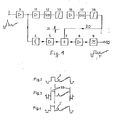
In Fig. 1 gelangt das nicht korrigierte Videosignal 1 von der Klemme 2 über den Verstärker 3, das Laufzeitglied 4 und den Verstärker 5 an die Addierstufe 7. Von dort gelangt das Videosignal über den Verstärker 8 und den Tiefpass 9 mit einer Grenzfrequenz von 3,0 MHz an die Ausgangsklemme 10, an der das korrigierte Videosignal 1' zur Verfügung steht.1, the
Vom Ausgang des Verstärkers 3 gelangt das Videosignal 1 ausserdem über den Verstärker 11 an die Differenzierstufe 12. Am Ausgang der Differenzierstufe 12 liegt der Amplitudenbegrenzer 13, der die Signalamplituden des differenzierten Signales in positiver und negativer Richtung begrenzt. Das derart differenzierte und in der Amplitude begrenzte Signal gelangt über den Verstärker 16 auf die zweite Differenzierstufe 17. Dieser ist ebenfalls ein Begrenzer 18 nachgeschaltet, der so wirkt wie der Begrenzer 13. Dadurch entsteht an der Leitung 20 das durch zweifache Differentiation und anschliessende Amplitudenbegrenzung gewonnene Korrektursignal 21. Dieses wird in der Addierstufe 7 dem Videosignal 1 im Sinne einer Korrektur, d.h. Flankenversteilerung, hinzugefügt. Die Amplitude des Korrektursignals 21 und die Begrenzerwerte der Begrenzer 13, 18 sind so gewählt, das bei kleinen Signalsprüngen im Videosignal 1 die Amplitudenbegrenzer 13, 18 praktisch unwirksam sind, das Korrektursignal 21 nicht begrenzt wird und eine erwünschte Versteilerung der Flanken im Videosignal auftritt, dass aber bei grösseren Signalsprüngen im Videosignal 1 im korrigierten Videosignal 1' keine zu grossen Spannungsspitzen auftreten, die die Bildwiedergabe oder die Synchronisierung stören können.From the output of the
Fig. 2 zeigt das nicht korrigierte Videosignal 1 an der Klemme 2. Das Videosignal enthält einen relativ breiten Schwarz/Weiss-Sprung, einen sogenannten 20T-lmpuls und fünf kleine Signalsprünge. Durch die Schaltung werden insbesondere diese kleinen Signalsprünge versteilert.FIG. 2 shows the
Figur 3 zeigt ein korrigiertes Videosignal, wie es in bekannter Weise mit einer Schaltung nach Figur 1 ohne die Begrenzer an der Klemme 10 stehen würde. Die fünf kleinen Signalsprünge erfahren eine erwünschte, eine subjektiv bessere Bildwiedergabe bewirkende Versteilerung. Bei den grösseren Signalsprüngen treten jedoch extrem hohe Spannungsspitzen 33 auf, die den dreifachen Wert der an sich im Videosignal enthaltenden Signalsprünge erreichen. Diese extrem hohen Signalsprünge führen zu einer subjektiven Bildverschlechterung. Da sie den Synchronboden der Zeilensynchronimpulse überschreiten, können sie bei der Bildwiedergabe auch die amplitudenabhängig arbeitende Zeilenablenkschaltung stören.FIG. 3 shows a corrected video signal as it would be in a known manner with a circuit according to FIG. 1 without the limiter at
Figur 4 zeigt das korrigierte Videosignal 1' an der Klemme 10, das bei Einsatz der Begrenzer 13, 18 in Figur 1 entsteht. Die fünf kleinen Signalsprünge erfahren etwa dieselbe Versteilerung wie in Figur 3, weil bei diesen Amplitudensprüngen die Begrenzer 13,18 unwirksam bleiben. Die unerwünschten grossen Spannungsspitzen 33 gemäss Figur 3 sind jedoch durch die Begrenzer 13, 18 stark reduziert.FIG. 4 shows the corrected
Die kombinierte Anwendung von Germanium-und Siliziumdioden beruht auf folgender Erkenntnis. Die Germaniumdiode ist im durchgeschalteten Zustand niederohmiger als eine Siliziumdiode, hat aber einen dynamischen Innenwiderstand im Durchlassbereich, der bei grossen Strömen in unerwünschter Weise grösser wird. Die Siliziumdiode ist zwar nicht so niederohmig wie eine Germaniumdiode, behält aber auch bei grossen Signalströmen annähernd einen konstanten dynamischen Innenwiderstand innerhalb des Durchlassbereiches. Bei der Erfindung werden nun die Vorteile der beiden verschiedenen Diodenarten in vorteilhafter Weise kombiniert. Durch diese Kombination ergibt sich insgesamt ein besonders kleiner Innenwiderstand im durchgeschalteten Bereich, der sowohl bei kleinen als auch bei grösseren Signalströmen wirksam ist. Durch diese Massnahme wird die Schaltereigenschaft der Dioden bei dem durch die Flussspannung gegebenen Schwellwert und damit die Wirkung des Begrenzers deutlich verbessert.The combined use of germanium and silicon diodes is based on the following knowledge. When switched on, the germanium diode has a lower resistance than a silicon diode, but has a dynamic internal resistance in the pass band, which becomes undesirably larger with large currents. Although the silicon diode is not as low-resistance as a germanium diode, it also maintains approximately a constant dynamic internal resistance within the passband even with large signal currents. The advantages of the two different types of diodes are now advantageously combined in the invention. This combination results in an overall particularly low internal resistance in the switched-through area, which is effective both with small and with larger signal currents. This measure significantly improves the switching properties of the diodes at the threshold value given by the forward voltage and thus the effect of the limiter.
In der Praxis hat sich gezeigt, dass Dioden mit den gewünschten Eigenschaften nicht immer mit ausreichender Stückzahl verfügbar sind. Es ist dann notwendig, für eine einwandfreie Funktion der Schaltung Dioden mit bestimmten Eigenschaften aus einer grossen Menge herauszusuchen. Eine derartige Lösung ist jedoch für die Serienfertigung ungeeignet. Wenn die Dioden nicht die gewünschten Eigenschaften haben, ist das angestrebte Schaltverhalten der Dioden zur Amplitudenbegrenzung nicht optimal.It has been shown in practice that diodes with the desired properties are not always available in sufficient numbers. It is then necessary to select diodes with certain properties from a large quantity for the circuit to function properly. However, such a solution is unsuitable for series production. If the diodes do not have the desired properties, the desired switching behavior of the diodes for amplitude limitation is not optimal.
Gemäss einer Weiterbildung der Erfindung wird daher die notwendige Begrenzung ohne Dioden realisiert, indem die Dioden durch die Kollektor-Emitter-Strecken von zwei gegensinnig gepolten Transistoren gleichen Typs gebildet sind, deren Kollektor jeweils mit der Basis verbunden ist.According to a development of the invention, the necessary limitation is therefore realized without diodes, in that the diodes are formed by the collector-emitter paths of two transistors of the same type which are polarized in opposite directions, the collectors of which are each connected to the base.
Durch die Anwendung von Transistoren als Dioden für die Begrenzung steht eine erhöhte Vielfalt von Halbleiterbauteilen zur Verfügung. Die Transistoren können in an sich bekannter Weise so geschaltet werden, dass sie die Aufgabe einer Diode erfüllen. Dabei besteht noch der Vorteil, dass ein als Diode geschalteter Transistor im. Durchlassbereich niederohmiger ist als eine Diode. Durch eine besondere Schaltung des Transistors gemäss einer Weiterbildung der Erfindung kann der Durchlasswiderstand des als Diode arbeitenden Transistors beeinflusst, z.B. absichtlich vergrössert werden. Das kann zweckmässig sein, um die gesamte Schaltung nicht durch einen zu niederohmig gesteuerten Transistor unerwünscht stark zu belasten und zu dämpfen.Through the use of transistors as diodes for the limitation, an increased variety of semiconductor components is available. The transistors can be switched in a manner known per se so that they perform the function of a diode. There is also the advantage that a transistor connected as a diode in the. Passband is lower resistance than a diode. The forward resistance of the transistor operating as a diode can be influenced, for example intentionally increased, by a special switching of the transistor according to a development of the invention. This can be useful in order to avoid the entire circuit due to a low-impedance controlled Transi Stor undesirably heavy and dampen.
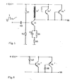
Ein Ausführungsbeispiel für diese Weiterbildung wird anhand der Figuren 5 und 6 erläutert. In Figur 5 wird das Videosignal 1 über den Kondensator 60 dem Transistor 11 zugeführt, dessen Basis-Vorspannung durch den Spannungsteiler 61, 62 bestimmt ist. Der Emitter des Transistors 11 ist über das RC-Glied mit dem Kondensator 63 und dem Widerstand 64 sowie über den Widerstand 65 geerdet. An der Klemme 66 steht das einmal differenzierte Korrektursignal, das gemäss Figur 1 einer weiteren Differenzierstufe zugeführt wird. Die Differentiation erfolgt mit der Induktivität 12' im Kollektorkreis des Transistors 11. Parallel zur Induktivität 12' sind die beiden Siliziumtransistoren 13', 14' antiparallel geschaltet, wobei jeweils der Kollektor mit der Basis verbundenist. Die Transistoren 13', 14' wirken in dieser Schaltung wie zwei antiparallel geschaltete Dioden. Ihr Durchlasswiderstand ist jedoch in erwünschter Weise wesentlich geringer. Bei bestimmten Bemessungen der gesamten Schaltung zur Verarbeitung des Videosignals kann durch die Schaltung nach Figur 1 der Durchlasswiderstand der Transistoren 13,14 unerwünscht niedrig werden und den Verstärker mit dem Transistor 11 unerwünscht stark bedämpfen.An embodiment of this development is explained with reference to Figures 5 and 6. In FIG. 5, the
In der Schaltung gemäss Figur 6 ist der Durchlasswiderstand der Transistoren 13', 14' dadurch absichtlich erhöht, dass jeweils der Kollektor mit der Basis über eine Diode 67, 68 verbunden ist. Durch die Dioden 67, 68 wird das Schalterverhalten der Transistoren 13', 14' weicher und der Durchlasswiderstand in erwünschter Weise erhöht. Dadurch kann eine geringere Belastung und Bedämpfung des Verstärkers mit dem Transistor 11 erreicht werden. Bei Siliziumtransistoren 13', 14' werden vorzugsweise Germaniumdioden 67, 68 verwendet, weil sie einen kleineren Durchlasswiderstand bei kleinen Signalamptituden haben als Siliziumdioden. Bei grossen Signalamplituden wächst der dynamische Innenwiderstand der Germaniumdioden, während er bei Siliziumdioden annähernd konstant bleibt. Die Paarung aus den Germaniumdioden 67, 68 und den Siliziumtransistoren 13', 14' zur Erhaltung eines schalter- ähnlichen Begrenzers mit definiertem Innenwiderstand ist daher vorteilhaft.In the circuit according to FIG. 6, the forward resistance of the transistors 13 ', 14' is intentionally increased by connecting the collector to the base via a
Bei einem praktisch erprobten Ausführungsbeispiel hatten die Bauteile folgende Werte.
- Transistor 11:
Typ 2N 2218 TR 13,14: Typ BC237B- R61: 10 KOhm
- R62: 10 KOhm
- C63: 50 µF
- R64:100Chm
- R65: 10 Ohm
Dioden 67, 68: AA143.
- Transistor 11:
Type 2N 2218 - TR 13.14: Type BC237B
- R61: 10 KOhm
- R62: 10 KOhm
- C63: 50 µF
- R64: 100 cm
- R65: 10 ohms
-
Diodes 67, 68: AA143.
In einem Videorecorder erfolgt bekanntlich die Aufzeichnung des Videosignals in Form eines mit dem Videosignal frequenzmodulierten Trägers. Die gesamte Übertragungskennlinie hat, bedingt durch den Frequenzgang des Aufzeichnungskopfes und des Magnetbandes, einen Abfall zu hohen Frequenzen hin. Gerade Signalanteile hoher Frequenz haben statistisch gesehen jedoch eine relativ kleine Amplitude. Zur Verbesserung der Wiedergabe bei feinen Bilddetails ist es daher bekannt, das Videosignal vor dem FM-Modulator über eine sogenannte Preemphasis zu führen, in der die hohen Frequenzen angehoben werden. Bei der Wiedergabe erfolgt in einer Deemphasis-Schaltung wieder eine entsprechende Absenkung der hohen Frequenzen. Dadurch wird für diese hohen Frequenzanteile auch der Störabstand verbessert. Wenn die Schaltung nach Fig. 1 in einem Videorecorder bei der Aufnahme vor der Preemphasisschaltung eingesetzt wird, liegen im Weg des Videosignals zwei Schaltungen, die etwa die gleiche Wirkung haben, nämlich eine Anhebung hoher Frequenzanteile. Durch das Zusammenwirken dieser beiden Schaltungen kann es bei Signalsprüngen zu unerwünscht hohen Amplituden des Videosignals kommen. Da die Maximalamplitude des Videosignals durch die Betriebsspannung begrenzt ist, kann dadurch eine Verfälschung des Verlaufs des Videosignals eintreten. Die Qualität des wiedergegebenen Bildes wird dadurch beeinträchtigt. Andererseits ist jedoch die genannte Preemphasis-Schaltung wegen der angewendeten Frequenzmodulation nicht entbehrlich.As is known, the video signal is recorded in a video recorder in the form of a carrier frequency-modulated with the video signal. Due to the frequency response of the recording head and the magnetic tape, the entire transmission characteristic has a drop towards high frequencies. Statistically speaking, high-frequency signal components in particular have a relatively small amplitude. To improve the reproduction of fine picture details, it is therefore known to guide the video signal in front of the FM modulator via a so-called pre-emphasis, in which the high frequencies are raised. During playback, the high frequencies are reduced accordingly in a de-emphasis circuit. This also improves the signal-to-noise ratio for these high frequency components. If the circuit according to FIG. 1 is used in a video recorder when recording before the pre-emphasis circuit, there are two circuits in the path of the video signal which have approximately the same effect, namely an increase in high frequency components. The interaction of these two circuits can lead to undesirably high amplitudes of the video signal in the event of signal jumps. Since the maximum amplitude of the video signal is limited by the operating voltage, the course of the video signal can be falsified. This affects the quality of the displayed image. On the other hand, however, the pre-emphasis circuit mentioned is not unnecessary because of the frequency modulation used.
Bei einer Weiterbildung der Erfindung wird mit einfachen Schaltungsmitteln die durch die Preemphasis hervorgerufene Signalverfälschung vermieden. Das wird dadurch erreicht, dass ein im Aufnahmeweg des Recorders vor einem Frequenzmodulator liegender, zur Preemphasis des Videosignals dienender Verstärker mit einem Gegenkopplungsnetzwerk mit zu hohen Frequenzen hin zunehmender Gegenkopplung versehen ist.In a further development of the invention, the signal falsification caused by the pre-emphasis is avoided with simple circuit means. This is achieved in that an amplifier located in the recording path of the recorder in front of a frequency modulator and used for preemphasis of the video signal is provided with a negative feedback network with negative feedback increasing towards high frequencies.
Diese Lösung beruht auf folgender Erkenntnis. Die bekannte Preemphasis-Schaltung hat eine Verstärkung, die mit steigender Frequenz ständig zunimmt. Das ist zwar für ein nicht gemäss Fig. 1 aufbereitetes Videosignal im Sinne einer einwandfreien Signalübertragung vorteilhaft. Wenn jedoch das Videosignal bereits gemäss Fig. 1 aufbereitet ist, ist die bei der Preemphasis-Schaltung wirksame, zu hohen Frequenzen hin zunehmende Verstärkung nachteilig, weil dann die hohe Frequenzen enthaltenden Signalsprünge zu stark überbetont werden. Dieser Nachteil wird dadurch beseitigt, dass die Preemphasis-Schaltung eine definierte, zu hohen Frequenzen hin zunehmende Gegenkopplung aufweist. Diese wirkt der in der Preemphasis-Schaltung an sich vorhandenen Verstärkungserhöhung zu hohen Frequenzen hin in vorteilhafter Weise entgegen. Die Preemphasis-Schaltung hat also zwei unabhängig voneinander wirkende frequenzabhängige Netzwerke. Das eine dient unverändert im Sinne der Preemphasis zur Erhöhung der Verstärkung zu hohen Frequenzen hin. Das andere dient zu einer definierten Verringerung der Verstärkung in einem bestimmten Frequenzbereich.This solution is based on the following knowledge. The known pre-emphasis circuit has a gain that increases continuously with increasing frequency. This is advantageous for a video signal not processed according to FIG. 1 in the sense of a perfect signal transmission. However, if the video signal has already been processed according to FIG. 1, the gain which is effective in the pre-emphasis circuit and increases towards high frequencies is disadvantageous because the signal jumps containing high frequencies are then overemphasized. This disadvantage is eliminated by the fact that the pre-emphasis circuit has a defined negative feedback that increases towards high frequencies. This advantageously counteracts the increase in amplification to high frequencies present in the pre-emphasis circuit. The pre-emphasis circuit therefore has two frequency-dependent networks which act independently of one another. One is still used in the sense of preemphasis to increase the gain towards high frequencies. The other serves to reduce the gain in a defined frequency range.
Ein Ausführungsbeispiel für diese Lösung wird anhand der Figuren 7 und 8 beschrieben.An embodiment of this solution is described with reference to Figures 7 and 8.
Figur 7 zeigt entsprechend Figur 1 das Videosignal 1 an der Klemme 2, den Verstärker 3, das Laufzeitglied 4, den Verstärker 5, die Addierstufe 7, den Verstärker 8, den Tiefpass 9 und die Klemme 10, an der das gemäss der Erfindung im Sinne einer Erhöhung der Bildschärfe aufbereitete Videosignal 1'steht. In der Addierstufe 7 wird dem Videosignal das Korrektursignal 21 hinzugefügt. Dieses wird in dem Weg mit dem Verstärker 11, der Differenzierstufe 12, dem Amplitudenbegrenzer 13, dem zweiten Verstärker 16, der zweiten Differenzierstufe 17 und dem zweiten Amplitudenbegrenzer 18 aus dem Videosignal 1 gewonnen.FIG. 7 shows the video image corresponding to FIG. 1
Das Videosignal 1' wird über die Leitung 30 und den Kondensator 31 der Preemphasis-Schaltung 32 zugeführt. Diese liefert an ihrem Ausgang das Videosignal über den Kondensator 33 an den FM-Modulator 34. Dieser erzeugt einen mit dem Videosignal frequenzmodulierten Träger, der mit dem Kopf 35 auf dem Magnetband 36 aufgezeichnet wird. Die Schaltung 32 enthält in bekannter Weise die zur Erzeugung der Basis-Vorspannung dienenden Widerständen 37, 38, den Transistor 39 mit dem Kollektor-Arbeitswiderstand 40, dem Emitterwiderstand 41 und dem frequenzabhängigen Gegenkopplungs-Netzwerk mit den Widerständen 42, 43 und den Kondensatoren 44, 45. Das Signal vom Ausgang des Transistors 39 gelangt über die Emitter-Folgerstufe mit dem Transistor 46 und dem Arbeitswiderstand 47 an den Ausgang der Schaltung 32. Das Netzwerk 42-45 bewirkt eine zu hohen Frequenzen hin abnehmende Gegenkopplung und damit ansteigende Verstärkung des Videosignals 1' für die Preemphasis.The video signal 1 'is fed to the
Die Schaltung 32 enthält zusätzlich das Gegenkopplungs-Netzwerk mit dem Widerstand 48 und dem Kondensator 49. Dieses Netzwerk bewirkt eine zu hohen Frequenzen hin zunehmende Gegenkopplung und damit eine abnehmende Verstärkung des Transistors 39. Die Zeitkonstante des Netzwerkes 48, 49 liegt in der Grössenanordnung von 200 ns, was einer Grenzfrequenz von etwa 0,9 M Hz entspricht.The
Figur 8a zeigt die Impulsform eines Rechteckimpulses, der durch eine bekannte Preemphasis-Schaltung, also ohne das Netzwerk 48, 49 und ohne Aufbereitung des Videosignals gemässFIG. 8a shows the pulse shape of a rectangular pulse, which according to a known pre-emphasis circuit, ie without the
Figur 1 aus einem Eingangsimpuls gemäss Figur 2b entsteht. Dieser Impuls hat die für die Aufzeichnung mit Frequenzmodulation notwendige Form. Bei Kombination der bekannten Preemphasis-Schaltung mit der Schaltung 2-18 in Figur 7 würde am Ausgang der Preemphasis-Schaltung ein Impuls gemäss Figur 8c entstehen. Die dargestellten Spannungsspitzen sind durch die Wirkung der Anhebung bei hohen Frequenzen an sich höher als dargestellt. Sie werden durch die Betriebsspannung in der Amplitude begrenzt. Durch diese Begrenzung tritt unabhängig von der Amplitudenänderung die unerwünschte Kurvenverformung von Figur 8a nach Figur 8c ein. Bei der Aufzeichnung dieses Signals würde sich bei der Wiedergabe ein verfälschter Impuls gemäss Figur 8d ergeben.Figure 1 arises from an input pulse according to Figure 2b. This pulse has the form necessary for recording with frequency modulation. If the known pre-emphasis circuit is combined with the circuit 2-18 in FIG. 7, a pulse according to FIG. 8 c would arise at the output of the pre-emphasis circuit. The voltage peaks shown are higher than shown as a result of the effect of the increase at high frequencies. They are limited in amplitude by the operating voltage. As a result of this limitation, the undesired curve deformation from FIG. 8a to FIG. 8c occurs regardless of the change in amplitude. When this signal was recorded, a distorted pulse according to FIG. 8d would result during playback.
Durch die Anwendung des Netzwerkes 48, 49 in der Schaltung 32 wird am Ausgang der Schaltung 32 ein Impuls gemäss Figur 8e erzeugt. Dieser Impuls hat etwa die gleiche Amplitude wie der Impuls gemäss Figur 8c, jedoch wieder die richtige Kurvenform gemäss Figur 8a. Bei der Aufzeichnung und anschliessenden Demodulation und Deemphasis entsteht daraus ein Impuls gemäss Figur 8f. Dieser hat wieder die gewünschte Kurvenform ähnlich wie in Figur 8b, jedoch durch die Anwendung der Schaltung 2-18 gemäss Figur 1 eine gewünschte Überbetonung der Sprünge, wie durch die Überschwinger 50 dargestellt ist. Diese Überbetonung bewirkt bei der Bildwiedergabe eine Bildverbesserung in Form einer schärferen Darstellung feiner Bilddetails bei hohen Frequenzen.By using the
Die Schaltung 32 wird von der Klemme 10 an ihren Eingang mit einem aufbereiteten Videosignal 1' mit einer Spitze-Spitze-Amplitude von etwa 1 V gespeist.The
In Figur 7 erfolgen die Preemphasis und die zur Verringerung der hochfrequenten Impulsspitzen eingeführte frequenzabhängige Gegenkopplung in derselben Verstärkerstufe mit dem Transistor 39. Das ist nicht unbedingt notwendig. Die Preemphasis und die genannte Gegenkopplung können auch in getrennten, im Signalweg aufeinanderfolgenden Stufen liegen.In FIG. 7, the pre-emphasis and the frequency-dependent negative feedback introduced to reduce the high-frequency pulse peaks take place in the same amplifier stage with the
Bei einem praktisch erprobten Ausführungsbeispiel hatten die Bauteile in der Schaltung 32 die folgenden Werte.

Bei Anwendung der Erfindung in einem Fernsehempfänger kann folgende Störung auftreten. Wenn der Empfänger nicht optimal abgestimmt ist, kann bei Anwendung der Schaltung das wiedergegebene Bild durch eine Bildplastik. und Rauschen beeinträchtigt werden. Unter bestimmten Bedingungen kann dann die Bildwiedergabe subjektiv schlechter sein als ohne Anwendung der Schaltung nach der Erfindung.When using the invention in a television receiver, the following interference can occur. If the receiver is not optimally tuned, the reproduced image can be replaced by an image plastic when using the circuit. and noise are affected. Under certain conditions, the image reproduction can then be subjectively worse than without using the circuit according to the invention.
Figuren 9 und 10 zeigen eine Weiterbildung der Erfindung, durch die bei nicht optimaler Abstimmung auftretende Störungen dadurch vermieden werden, dass die Amplitude. des Korrektursignals mit steigender Amplitude der Signalanteile im oberen Frequenzbereich des nichtkorrigierten Videosignalsverringertwird.FIGS. 9 and 10 show a development of the invention, by means of which disturbances occurring in the case of non-optimal coordination are avoided by the amplitude. of the correction signal is reduced with increasing amplitude of the signal components in the upper frequency range of the uncorrected video signal.
Diese Lösung beruht auf folgender Erkenntnis. Die nach subjektiven Empfinden vorgenommene nicht optimale Abstimmung erfolgt meist in dem Sinne, dass die hohen Frequenzanteile im Videosignal angehoben werden, was oft subjektiv als schärferes Bild empfunden und allgemein als «Anspitzung» bezeichnet wird. Die Schaltung nach Fig. 1 wirkt nun ebenfalls in dem Sinne, dass hohe Frequenzanteile angehoben werden. Durch die gleichzeitige Fehlabstimmung im Sinne einer Anspitzung und die Wirkung der Schaltung nach Fig. 1 kommt es dann insgesamt zu einer zu starken Anhebung der hohen Frequenzanteile, wodurch sich die Bildplastik und das Rauschen erklären lassen. Die nicht optimale Abstimmung durch frequenzselektive Auswertung des Videosignals automatisch ermittelt und in Abhängigkeit davon selbsttätig die Wirkung der Schaltung nach Fig. 1 verringert. Hierzu kann die Korrekturspannung kontinuierlich bei steigender Amplitude der Signalanteile hoher Frequenz im Videosignal verringert werden. Eine andere Ausführung besteht darin, das Korrektursignal vollständig abzuschalten, wenn die Signalanteile höherer Frequenz im Videosignal einen bestimmten Schwellwert überschreiten. Bei einer Fehlabstimmung ist dann zwar die Schaltung nach der Fig. 1 wirkungslos und trägt somit zur Bildverbesserung nicht bei. Es wird jedoch verhindert, dass für die Fälle einer Fehlabstimmung die Schaltung nach Fig. 1 in unerwünschter Weise die Bildqualität beeinträchtigt.This solution is based on the following knowledge. The suboptimal adjustment made according to subjective feelings usually takes place in the sense that the high frequency components in the video signal are raised, which is often perceived subjectively as a sharper picture and is generally referred to as “sharpening”. The circuit according to FIG. 1 now also works in the sense that high frequency components are raised. The simultaneous mismatch in the sense of a sharpening and the effect of the circuit according to FIG. 1 then leads to an excessive increase in the high frequency components, which explains the image plastic and the noise. The non-optimal tuning is automatically determined by frequency-selective evaluation of the video signal and, depending on this, automatically reduces the effect of the circuit according to FIG. 1. For this purpose, the correction voltage can be reduced continuously as the amplitude of the high frequency signal components in the video signal increases. Another embodiment consists in completely switching off the correction signal when the signal components of higher frequency in the video signal exceed a certain threshold value. In the event of a mismatch, the circuit according to FIG. 1 is ineffective and thus does not contribute to image improvement. However, the circuit of FIG. 1 is prevented from undesirably affecting the image quality in the event of a mismatch.
In Figur 9 gelangt das Videosignal 1 von der Klemme 2 über den Verstärker 3, das Laufzeitglied 4, den Verstärker 5, die Addierstufe 7, den Verstärker 8 und den Tiefpass 9 an die Klemme 10, an der das gemäss Fig. 1 im Sinne einer Erhöhung der Bildschärfe aufbereitete Videosignal 1' steht. In der Addierstufe 7 wird dem Videosignal das Korrektursignal 21 hinzugefügt. Dieses wird in dem Weg mit dem Verstärker 11, der Differenzierstufe 12, dem Amplitudenbegrenzer 13, dem zweiten Verstärker 16, der zweiten Differenzierstufe 17 und dem zweiten Amplitudenbegrenzer 18 aus dem Videosignal 1 gewonnen. Die dargestellte Schaltung ist mit ihren Klemmen 2, 10 in den Leuchtdichtesignalweg eines Farbfernsehempfängers eingebaut.In Figure 9, the
In den Weg der Korrekturspannung 21 vom Ausgang des Begrenzers 18 zum Eingang der Addierstufe 7 ist zusätzlich das Tor 70 eingefügt, das bei optimal abgestimmtem Fernsehempfänger durchlässig ist.In the path of the
Das Videosignal vom Ausgang des Verstärkers 5 gelangt zu dem Filter 71, das einen Durchlassbereich bei etwa 2-3 MHz aufweist. Bei einer Fehlabstimmung des Empfängers sind die Signalanteile in diesem Frequenzbereich stark angehoben, so dass am Ausgang des Filters 71 eine überhöhte Spannung auftritt. Diese Spannung wird in dem Gleichrichter 72 gleichgerichtet. Wenn die gleichgerichtete Spannung einen bestimmten Schwellwert übersteigt, entsteht in einer nicht näher dargestellten Schwellwertschaltung die Schaltspannung 73. Diese Schaltspannung steuert das Tor 70 undurchlässig, so dass die Korrekturspannung 21 nicht mehr zur Addierstufe 7 gelangt. Die Korrekturschaltung 11-13, 16-18 ist dann in erwünschter Weise wirkungslos. Wenn der Empfänger wieder richtig abgestimmt ist, sinkt die Amplitude der Signalanteile im oberen Frequenzbereich des Videosignals am Ausgang des Verstärkers 5 wieder ab. Die Schaltspannung 73 verschwindet dann, und das Tor 70 wird wieder durchlässig gesteuert. Die Korrekturspannung 21 gelangt dann wieder in erwünschter Weise auf die Addierstufe 7.The video signal from the output of the
In Figur 10 gelangt das Videosignal vom Ausgang des Verstärkers 5 über den Kondensator 74 auf die Basis des Transistors 75, dessen Basisvorspannung mit dem Spannungsteiler 76, 77 erzeugt wird und dessen Emitter über den Widerstand 78 geerdet ist. Im Kollektorkreis des Transistors 75 liegt das auf 2-3 MHz abgestimmte Filter 71, das mit dem Widerstand 79 bedämpft ist. Durch die mit der Induktivität des Filters 71 gekoppelte Spule 80 werden die Signalanteile im Frequenzbereich von 2-3 MHz ausgekoppelt und über den Gleichrichter 72 der Basis des Transistors 81 zugeführt. Die Basis ist über den Widerstand 82 geerdet. Der Kollektor ist an die Basis des Transistors 16a angeschlossen, der den Verstärker 16 in Figur 1 darstellt. Die Basisvorspannung für den Transistor 16a wird mit den Widerständen 83, 84 erzeugt. Der Emitter des Transistors 16a ist über den Widerstand 85 und den Kondensator 86 geerdet. Die Differenzierstufe ist durch die Induktivität 17a gebildet und der Amplitudenbegrenzer 18 durch zwei antiparallel geschaltete Dioden 18a. Das Videosignal gelangt von dem Begrenzer 13 über den Kondensator 87 auf die Basis des Transistors 16a.In FIG. 10, the video signal passes from the output of the
Bei optimal abgestimmtem Fernsehempfänger sind die am Filter 71 entstehenden Signalanteile und die daraus gewonnene Gleichspannung an der Basis des Transistors 81 so gering, dass der Transistor 81 gesperrt bleibt und auf die Funktion des Transistors 16a keinen Einfluss hat. Die Korrekturspannung 21 gelangt dann zwecks Schärfeerhöhung auf den Eingang der Addierstufe 7.In the case of an optimally tuned television receiver, the signal components produced at the
Bei nicht optimaler Abstimmung wird die Gleichspannung an der Basis des Transistors 81 so gross, dass der Transistor 81 leitet und die Basis des Transistors 16a erdet. Dadurch verschwindet die Korrekturspannung 21 am Eingang der Addierstufe 7. Der Transistor 81 wirkt also als Amplitudenschwellwert-Schaltung und der Transistor 16a als Tor 70 in Figur 9.If the tuning is not optimal, the DC voltage at the base of
Der Tiefpass 9 hat vorzugsweise in einem Farbfernsehempfänger die Grenzfrequenz von 3,5 MHz. Ein Tiefpass mit der gleichen Grenzfrequenz ist vorzugsweise in Reihe zum Verstärker 3 vorgesehen.The
Bei einem praktisch erprobten Ausführungsbeispiel hatten die Bauteile in Figur 10 die folgenden Werte:

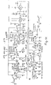
Fig. 11 zeigt eine praktisch erprobte Schaltung gemäss dem Blockschaltbild nach Fig. 1, wobei einander entsprechende Teile mit gleichen Bezugsziffern versehen sind. Im Weg des Videosignals 1 liegen der Transistor 30, der Tiefpass 31 mit einer Grenzfrequenz von 3,0 M Hz, der Transistor 32 und der als Emitterfolger betriebene Transistor 23. Der Schaltungspunkt 6 an der Basis des Transistors 27 ist der Punkt, an dem das Videosignal und das Korrektursignal 21 addiert werden. Die Spule 212 im Kollektorkreis des Transistors 211 wirkt als Differenzierglied. Parallel zur Spule 212 liegen antiparallel geschaltete Siliziumdioden 213,214.FIG. 11 shows a circuit that has been tried and tested in accordance with the block diagram according to FIG. 1, parts which correspond to one another are provided with the same reference numbers. In the path of the
Durch die Dioden 213, 214 tritt eine Begrenzerwirkung bei einer Spannung von etwa 0,2 Volt ein. Der Transistor 216 bildet die zweite Verstärkerstufe und die Spule 217 das zweite Differenzierglied. Die Dioden 218, 219 bewirken wieder die Amplitudenbegrenzung. Das Korrektursignal gelangt vom Kollektor des Transistors 216 auf die Schaltung 15, die nur Signale oberhalb eines bestimmten Schwellwertes durchlässt und dadurch Rauschen unterhalb dieses Schwellwertes unterdrückt. Das am Ausgang der Schaltung 15 stehende Korrektursignal gelangt dann auf die beiden Begrenzer 90, 91, die zusätzlich das Korrektursignal in positiver und negativer Richtung begrenzen, so dass das Korrektursignal 21 an dem Schaltungspunkt 6 die optimale maximale Amplitude relativ zum Videosignal 1 hat.The
Bei einem praktisch erprobten Ausführungsbeispiel wurden für die in Figur 11 dargestellten Halbleiterbauteile follgende Typen verwendet.
Transistoren 11, 16: Typ 2N2218- alle anderen Transistoren: Typ BC 237B
- Siliziumdioden: 13,14,18,19: Typ BAY95
- Germaniumdioden: 13', 14', 18', 19': Typ AAZ10.
-
Transistors 11, 16: Type 2N2218 - all other transistors: type BC 237B
- Silicon diodes: 13, 14, 18, 19: type BAY95
- Germanium diodes: 13 ', 14', 18 ', 19': type AAZ10.
Claims (10)
Priority Applications (1)
| Application Number | Priority Date | Filing Date | Title |
|---|---|---|---|
| AT82109220T ATE18619T1 (en) | 1981-10-14 | 1982-10-06 | CIRCUIT FOR DEPARTING THE EDGES OF A VIDEO SIGNAL, ESPECIALLY FOR A VIDEO RECORDER. |
Applications Claiming Priority (4)
| Application Number | Priority Date | Filing Date | Title |
|---|---|---|---|
| DE3140761 | 1981-10-14 | ||
| DE19813140761 DE3140761C2 (en) | 1981-10-14 | 1981-10-14 | Circuit for steepening the edges of a video signal, especially for a video recorder |
| DE3206685 | 1982-02-25 | ||
| DE3206685 | 1982-02-25 |
Publications (2)
| Publication Number | Publication Date |
|---|---|
| EP0077010A1 EP0077010A1 (en) | 1983-04-20 |
| EP0077010B1 true EP0077010B1 (en) | 1986-03-12 |
Family
ID=25796691
Family Applications (1)
| Application Number | Title | Priority Date | Filing Date |
|---|---|---|---|
| EP82109220A Expired EP0077010B1 (en) | 1981-10-14 | 1982-10-06 | Circuit for reducing the rise-time of the flanks of a video signal, in particular for a video recorder |
Country Status (2)
| Country | Link |
|---|---|
| EP (1) | EP0077010B1 (en) |
| DE (1) | DE3269852D1 (en) |
Families Citing this family (9)
| Publication number | Priority date | Publication date | Assignee | Title |
|---|---|---|---|---|
| DE3307014A1 (en) * | 1983-02-28 | 1984-08-30 | Telefunken Fernseh Und Rundfunk Gmbh, 3000 Hannover | Circuit for improving the image sharpness in a video recorder |
| JPS59186493A (en) * | 1983-04-07 | 1984-10-23 | Victor Co Of Japan Ltd | Processor of color video signal |
| DE3400674C1 (en) * | 1984-01-11 | 1985-03-21 | Deutsche Thomson-Brandt Gmbh, 7730 Villingen-Schwenningen | Circuit for steepening the edges of a video signal |
| US4706113A (en) * | 1985-02-18 | 1987-11-10 | Mitsubishi Denki Kabushiki Kaisha | Contour detecting filter device using PAL samples of composite video signals without separation of luminance signals therefrom |
| DE3713225C1 (en) * | 1987-04-18 | 1988-08-11 | Standard Elektrik Lorenz Ag | Video device with a recording medium |
| US4935806A (en) * | 1988-12-30 | 1990-06-19 | Zenith Electronics Corporation | Chroma noise reduction and transient improvement |
| DE3940128A1 (en) * | 1989-04-27 | 1990-10-31 | Thomson Brandt Gmbh | CIRCUIT FOR PROCESSING A LUMINOUS SIGNAL SIGNAL |
| KR920010186B1 (en) * | 1990-10-30 | 1992-11-19 | 주식회사 금성사 | Picture control system of vcr |
| GB2253964A (en) * | 1991-03-20 | 1992-09-23 | Rank Cintel Ltd | Treatment of video signals produced by aperture correctors |
Family Cites Families (6)
| Publication number | Priority date | Publication date | Assignee | Title |
|---|---|---|---|---|
| DE1512688A1 (en) * | 1967-01-18 | 1969-06-12 | Fernseh Gmbh | Circuit arrangement for double-sided amplitude limitation of electrical signals |
| JPS5286010A (en) * | 1976-01-12 | 1977-07-16 | Sony Corp | Pre-emphasis circuit |
| GB1579138A (en) * | 1976-07-06 | 1980-11-12 | Sony Corp | Noise and cross-talk elimination in recording and reproducing video signals |
| JPS5327010A (en) * | 1976-08-25 | 1978-03-13 | Sony Corp | Signal tran smitter |
| JPS5412714A (en) * | 1977-06-29 | 1979-01-30 | Matsushita Electric Ind Co Ltd | Recorder-reproducer |
| JPS55117712A (en) * | 1979-02-28 | 1980-09-10 | Matsushita Electric Ind Co Ltd | Noise reduction circuit of video signal recording and reproducing device |
-
1982
- 1982-10-06 EP EP82109220A patent/EP0077010B1/en not_active Expired
- 1982-10-06 DE DE8282109220T patent/DE3269852D1/en not_active Expired
Also Published As
| Publication number | Publication date |
|---|---|
| EP0077010A1 (en) | 1983-04-20 |
| DE3269852D1 (en) | 1986-04-17 |
Similar Documents
| Publication | Publication Date | Title |
|---|---|---|
| DE3430933C2 (en) | ||
| DE2828586C2 (en) | Video signal recording and reproduction system | |
| DE1908247A1 (en) | Circuit arrangement for reducing interference of higher frequencies (noise) in broadband electrical signals, in particular television signals | |
| DE2733350C2 (en) | Circuit arrangement for eliminating amplitude fluctuations when reproducing a signal recorded on a recording medium | |
| DE3315663C2 (en) | Circuit for dynamic suppression of small alternating signal amplitudes for an image display system | |
| EP0077010B1 (en) | Circuit for reducing the rise-time of the flanks of a video signal, in particular for a video recorder | |
| DE2730131C2 (en) | ||
| EP0098015B1 (en) | Circuit arrangement for increasing the edge sharpness of a video signal | |
| DE2822837A1 (en) | ARRANGEMENT TO REDUCE THE CONTENT OF INTERFERENCE IN USEFUL SIGNALS | |
| DE3237421A1 (en) | ARRANGEMENT FOR AUTOMATIC AND MANUAL CONTROL OF THE AMPLIFIER IN VIDEO SIGNALS | |
| DE2547143A1 (en) | CIRCUIT ARRANGEMENT FOR THE AUTOMATIC BANDWIDTH REGULATION OF A LUMINOUS CHANNEL | |
| DE2613071B2 (en) | DEVICE FOR SUPPRESSION OF SINGULAR EFFECT IN TELEVISION SIGNALS | |
| DE3011726C2 (en) | Stabilized automatic brightness control circuit in a video signal processing system with automatic beam storm limiter | |
| DE3214607C2 (en) | ||
| DE3311883C2 (en) | Circuit for steepening video signals | |
| DE3140761C2 (en) | Circuit for steepening the edges of a video signal, especially for a video recorder | |
| DE3516913C1 (en) | Automatic FM sideband level control for video recorders | |
| DE1951295B2 (en) | CONTROLLED TRANSISTOR AMPLIFIER | |
| DE3030313C2 (en) | Circuit for suppressing high-frequency interference in a television receiver | |
| DE3443628A1 (en) | TELEVISION IF SWITCHING FOR QUASI PARALLEL STEREO TONE RECEPTION | |
| DE2919164C3 (en) | Video signal equalization circuit | |
| DE3237422C2 (en) | Frequency selective signal processing circuit | |
| DE3400674C1 (en) | Circuit for steepening the edges of a video signal | |
| DE3725683C2 (en) | Video signal recorder | |
| DE2854828C2 (en) |
Legal Events
| Date | Code | Title | Description |
|---|---|---|---|
| PUAI | Public reference made under article 153(3) epc to a published international application that has entered the european phase |
Free format text: ORIGINAL CODE: 0009012 |
|
| AK | Designated contracting states |
Designated state(s): AT BE CH DE FR GB IT LI LU NL SE |
|
| 17P | Request for examination filed |
Effective date: 19830824 |
|
| ITF | It: translation for a ep patent filed |
Owner name: BARZANO' E ZANARDO MILANO S.P.A. |
|
| GRAA | (expected) grant |
Free format text: ORIGINAL CODE: 0009210 |
|
| RAP1 | Party data changed (applicant data changed or rights of an application transferred) |
Owner name: TELEFUNKEN FERNSEH UND RUNDFUNK GMBH |
|
| AK | Designated contracting states |
Kind code of ref document: B1 Designated state(s): AT BE CH DE FR GB IT LI LU NL SE |
|
| REF | Corresponds to: |
Ref document number: 18619 Country of ref document: AT Date of ref document: 19860315 Kind code of ref document: T |
|
| REF | Corresponds to: |
Ref document number: 3269852 Country of ref document: DE Date of ref document: 19860417 |
|
| ET | Fr: translation filed | ||
| PLBI | Opposition filed |
Free format text: ORIGINAL CODE: 0009260 |
|
| 26 | Opposition filed |
Opponent name: GRUNDIG E.M.V. ELEKTRO-MECHANISCHE VERSUCHSANSTALT Effective date: 19861210 |
|
| NLR1 | Nl: opposition has been filed with the epo |
Opponent name: GRUNDIG E.M.V. MAX GRUNDIG HOLLAEND STIFTUNG & CO. |
|
| PGFP | Annual fee paid to national office [announced via postgrant information from national office to epo] |
Ref country code: SE Payment date: 19901018 Year of fee payment: 9 |
|
| PGFP | Annual fee paid to national office [announced via postgrant information from national office to epo] |
Ref country code: GB Payment date: 19910731 Year of fee payment: 10 |
|
| PGFP | Annual fee paid to national office [announced via postgrant information from national office to epo] |
Ref country code: AT Payment date: 19911010 Year of fee payment: 10 |
|
| PGFP | Annual fee paid to national office [announced via postgrant information from national office to epo] |
Ref country code: FR Payment date: 19911017 Year of fee payment: 10 |
|
| ITTA | It: last paid annual fee | ||
| PGFP | Annual fee paid to national office [announced via postgrant information from national office to epo] |
Ref country code: NL Payment date: 19911031 Year of fee payment: 10 Ref country code: CH Payment date: 19911031 Year of fee payment: 10 |
|
| PGFP | Annual fee paid to national office [announced via postgrant information from national office to epo] |
Ref country code: DE Payment date: 19911224 Year of fee payment: 10 |
|
| RDAG | Patent revoked |
Free format text: ORIGINAL CODE: 0009271 |
|
| STAA | Information on the status of an ep patent application or granted ep patent |
Free format text: STATUS: PATENT REVOKED |
|
| 27W | Patent revoked |
Effective date: 19911128 |
|
| GBPR | Gb: patent revoked under art. 102 of the ep convention designating the uk as contracting state | ||
| REG | Reference to a national code |
Ref country code: CH Ref legal event code: PL |
|
| NLR2 | Nl: decision of opposition | ||
| PGFP | Annual fee paid to national office [announced via postgrant information from national office to epo] |
Ref country code: LU Payment date: 19920924 Year of fee payment: 11 |
|
| PGFP | Annual fee paid to national office [announced via postgrant information from national office to epo] |
Ref country code: BE Payment date: 19921028 Year of fee payment: 11 |
|
| EPTA | Lu: last paid annual fee | ||
| EUG | Se: european patent has lapsed |
Ref document number: 82109220.2 Effective date: 19920311 |
|
| APAH | Appeal reference modified |
Free format text: ORIGINAL CODE: EPIDOSCREFNO |