EP0076969A1 - Perpendicular magnetic recording head - Google Patents
Perpendicular magnetic recording head Download PDFInfo
- Publication number
- EP0076969A1 EP0076969A1 EP82108980A EP82108980A EP0076969A1 EP 0076969 A1 EP0076969 A1 EP 0076969A1 EP 82108980 A EP82108980 A EP 82108980A EP 82108980 A EP82108980 A EP 82108980A EP 0076969 A1 EP0076969 A1 EP 0076969A1
- Authority
- EP
- European Patent Office
- Prior art keywords
- pole
- side member
- recording head
- coil
- magnetic recording
- Prior art date
- Legal status (The legal status is an assumption and is not a legal conclusion. Google has not performed a legal analysis and makes no representation as to the accuracy of the status listed.)
- Granted
Links
Images

Classifications
-
- G—PHYSICS
- G11—INFORMATION STORAGE
- G11B—INFORMATION STORAGE BASED ON RELATIVE MOVEMENT BETWEEN RECORD CARRIER AND TRANSDUCER
- G11B5/00—Recording by magnetisation or demagnetisation of a record carrier; Reproducing by magnetic means; Record carriers therefor
- G11B5/127—Structure or manufacture of heads, e.g. inductive
- G11B5/1278—Structure or manufacture of heads, e.g. inductive specially adapted for magnetisations perpendicular to the surface of the record carrier
-
- G—PHYSICS
- G11—INFORMATION STORAGE
- G11B—INFORMATION STORAGE BASED ON RELATIVE MOVEMENT BETWEEN RECORD CARRIER AND TRANSDUCER
- G11B5/00—Recording by magnetisation or demagnetisation of a record carrier; Reproducing by magnetic means; Record carriers therefor
- G11B5/127—Structure or manufacture of heads, e.g. inductive
- G11B5/17—Construction or disposition of windings
Definitions
- the present invention relates to a perpendicular magnetic recording head for recording a high density signal by forming magnetization perpendicular to the plane of a magnetic recording medium.
- a perpendicular magnetic recording for recording high density signals by forming magnetization perpendicular to the plane of a magnetic recording medium has drawn attention.
- a magnetic head used in this kind of recording was disclosed, for example, in Japanese Patent Disclosure Nos. 56-87217, 56-87219 and 56-87220.
- the magnetic head includes a magnetic pole formed of a highly permeable thin magnetic film the end of which faces the magnetic surface of a recording medium, a side member formed of a highly permeable magnetic material which is jointed with the film surface of the pole, an exciting coil wound around the pole via the side member, and a nonmagnetic holder for holding the pole and the side member. It was, however, very difficult in a magnetic head of this type to reduce the size of the components so as to increase recording efficiency. Particularly, it has been desired to provide a magnetic head which has high durability and reliability for practical use in a perpendicular magnetic recording system.
- a perpendicular magnetic recording head which comprises a pole formed of a highly permeable magnetic thin film the end of which faces the magnetic surface of a recording medium, a side member formed of a highly permeable magnetic material joined with the film surface of the pole, a nonmagnetic holder for holding the pole and the side member and having a coil hole which is gradually increased in width from the end of the side member toward the rear, and an exciting coil wound around the pole via the side member through the coil hole.
- the perpendicular magnetic recording head thus constructed permits high recording efficiency as well as the improvements in the durability and the reliability of the pole formed of a magnetic thin film. Further, this perpendicular magnetic recording head can also sufficiently perform the superior characteristics of the side member which is joined with the film surface of the pole. As a consequence, the perpendicular magnetic recording head according to the present invention is constructed simply and still provides high utility.
- a thus far proposed magnetic head shown in Fig. 1 includes a pole 10 formed of a highly permeable magnetic thin film, a side member 12, a nonmagnetic holder 14 for holding the pole 10 and the side member 12, and an exciting coil 16 wound around the pole 10 via the side member 12.
- the end of the pole 10 faces the magnetic surface of a recording medium.
- a magnetic head of this type is called "a main-pole-driven magnetic recording head".
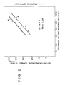
- curves a and ⁇ represent the results of the saturation recording currents obtained by using different recording media.
- the ratio D/Tg of the protrusion length D of the pole to the thickness T S of the side member is set to unity, and the thickness Tm of the pole is set to 2 ⁇ m.
- a coil hole 18 is formed in a rectangular shape, and the upper surface of the nonmagnetic holder 14 for holding the pole 10 and the side member 12 is formed in a curved surface.
- the present invention has been performed on the basis that the recording efficiency of a perpendicular agnetic recording head can be improved by reducing the tickness Tg of the side member and the protrusion length D of the pole from the side member.
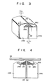
- An embodiment of the present invention will now be described in more detail with reference to Figs. 3 and 4.
- the magnetic head according to the present invention comprises a pole 20 formed of a high permeability magnetic thin film, a side member 22 intimately formed with the side surface of the pole 20, a pair of nonmagnetic holders 24a, 24b, and an exciting coil 26 wound around the pole 20 and the side member 22.
- the pole 20 is formed, for example, of permalloy or amorphous alloy.
- the side member 22 is formed, for example, of Mn-Zn ferrite, and is in intimate contact with the side surface of the pole 20.
- the side member 22 is formed, for example, to be buried in a first nonmagnetic holder 24a which is formed of glass or ceramic.
- the surfaces of the side member 22 and nonmagnetic holder 24a are formed in the same plane.
- the pole 20 is intimately formed by a deposition in a predetermined width on the side surface of the side member 22.
- the second nonmagnetic holder 24b is secured with an adhesive to the forming surface of the pole 20.
- Coil holes 28a, 28b formed in a triangular shape as seen from the front side are respectively formed at the ends of the nonmagnetic holders 24a, 24b.
- the coil holes 28a, 28b are respecitively gradually increased in the width from the ends toward the rear.
- the upper ends 30a, 30b of the coil holes are respectively formed of a rectilinear line or curve similar to the rectilinear line - forming an angle 8 with respect to the horizontal line.
- a wire material 32 for the coil is wound around the pole 20 and the side member 22, thereby forming the coil 26 for exciting the pole 20.
- This coil 26 is disposed within the triangular-shaped coil holes 28a, 28b.
- the end of the pole 20 serves as a recording head surface, and the ends of the nonmagnetic holders 24a, 24b polished in a circular-arc shape serve as the sliding surface on a recording medium 34.
- the upper ends 30a, 30b of the respecitive coil holes 28a, 28b are so formed as to produce an angle 9 with respect to the horizontal line. Therefore, the ends of the nonmagnetic holders 24a, 24b are polished in a circular-arc shape without being limited to the positions of the coil holes 28a, 28b. In this manner, the thickness Tg of the side member 22 and the protrusion length D of the pole 20 from the side member 22 can be advantageously reduced. As a consequence, the recording sensitivity of the perpendicular magnetic recording head of the present invention can be remarkably improved.
- the pole 20 is in intimate contact with the side surfaces of the side member 22 and the first nonmagnetic holder 24a and the second nonmagnetic holder 24b are lapped on the pole 20 to be rigidly held. Therefore, the pole 20 can be made mechanically very stable though it is formed in thin film.
- the end of the pole 20 is further rigidly held with the ends of the first and second nonmagnetic holders 24a, 24b. Therefore, the pole 20 is stabilized against the external force produced upon moving of the recording medium 34.
- the first nonmagnetic holder 24a in intimate contact with the pole 20 is disposed at the downstream side with respect to the moving direction of the recording medium, the downstream-side edge of the pole end which directly relates to the perpendicular magnetic recording becomes very sharp. In this manner, this magnetic recording head can perform perpendicular magnetic recording of high resoluction. According to the present invention, there is thus provided a perpendicular magnetic recording head having extremely high recording efficiency, excellent durability and high reliability.
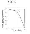
- Fig. 5 shows variations in the exciting magnetic field strength with respect to the angle 6 formed between the coil holes 28a, 28b and the horizontal line (the moving direction of the recording medium).
- the exciting coil 26 is filled in the coil holes 28a, 28b.
- the exciting magnetic field strength is the mean exciting magnetic field strength of the side member 22 from the upper end of the side member 22 to the position of 100 ⁇ m from the upper end of the side member 22 which mainly contributes to the magnetization at the end of the pole 20.
- the suitable value of the 6 is thus selected to be less than 50° and the reducing step described above is taken, in which the side member 22 is reduced in thickness and the protrusion length of the pole is shortened, then the total recording efficiency of the perpendicular magnetic recording head of the present invention can be remarkably improved, overcoming the reduced efficiency due to the increase in the exciting magnetic field strength.
- the thickness T S of the side member 22 was formed to approx. 100 ⁇ m.
- the thickness T S of the side member 22 can be formed to 10 ⁇ m, and the protrusion length D of the pole 20 can be reduced to 10 pm. Therefore, as shown in Fig. 2, the saturation recording current can be reduced to 1/10 as compared with the thus far proposed magnetic head. Accordingly, the recording efficiency can be improved by 20 dB.
- the decrease in the efficiency due to the inclination of the coil holes 30a, 30b is more or less -1.4 dB in the range of 0 ⁇ 50° as shown in Fig. 4. Therefore, the total recording efficiency can be improved by 18.6 dB.
- the protrusion length of the pole can be reduced merely to 70 to 80 ⁇ m.
- the curvature of the upper surfaces of the nonmagnetic holders 24a, 24b should be limited to less than a predetermined value. As a resut, the recording efficiency of the thus far proposed magnetic head can be improved more or less 2 to 3 dB.
- the upper ends of the coil holes 28a, 28b may be a curved line bent suitably in a range so as to not lose the recording efficiency.
- the shape of the coil hole may also be any shape in addition to the triangular shape described above.
- the coil hole may be a rhombic shape.
- the angle a formed between the upper end surfaces 30a, 30b of the coil hole and the horizontal plane may be larger than an angle formed between the upper end surface of the nonmagnetic holder and the horizontal plane.
- the side members 22 may be respectively provided at both side surfaces of the pole 20.
- the width, the thickness and the material of the pole 20 may be determined in response to the specifications.
- the present invention may also be applied similarly to the magnetic head of a mainpole- driven magnetic recording head which includes an auxiliary pole.
- various other changes and modifications may be made within the spirit and scope of the present invention.
Abstract
Description
- The present invention relates to a perpendicular magnetic recording head for recording a high density signal by forming magnetization perpendicular to the plane of a magnetic recording medium.
- A perpendicular magnetic recording for recording high density signals by forming magnetization perpendicular to the plane of a magnetic recording medium has drawn attention. A magnetic head used in this kind of recording was disclosed, for example, in Japanese Patent Disclosure Nos. 56-87217, 56-87219 and 56-87220. The magnetic head includes a magnetic pole formed of a highly permeable thin magnetic film the end of which faces the magnetic surface of a recording medium, a side member formed of a highly permeable magnetic material which is jointed with the film surface of the pole, an exciting coil wound around the pole via the side member, and a nonmagnetic holder for holding the pole and the side member. It was, however, very difficult in a magnetic head of this type to reduce the size of the components so as to increase recording efficiency. Particularly, it has been desired to provide a magnetic head which has high durability and reliability for practical use in a perpendicular magnetic recording system.
- It is an object of the present invention to provide a perpendicular magnetic recording head which permits perpendicular magnetic recording of a signal with high efficiency.
- In order to achieve the above object, there is provided according to the present invention a perpendicular magnetic recording head which comprises a pole formed of a highly permeable magnetic thin film the end of which faces the magnetic surface of a recording medium, a side member formed of a highly permeable magnetic material joined with the film surface of the pole, a nonmagnetic holder for holding the pole and the side member and having a coil hole which is gradually increased in width from the end of the side member toward the rear, and an exciting coil wound around the pole via the side member through the coil hole.
- The perpendicular magnetic recording head thus constructed permits high recording efficiency as well as the improvements in the durability and the reliability of the pole formed of a magnetic thin film. Further, this perpendicular magnetic recording head can also sufficiently perform the superior characteristics of the side member which is joined with the film surface of the pole. As a consequence, the perpendicular magnetic recording head according to the present invention is constructed simply and still provides high utility.
- Other objects and advantages will become apparent from the following description taken in conduction with the accompanying drawings in which:
- Fig. 1 is a perspective view of a thus far proposed perpendicular magnetic recording head;
- Fig. 2 is a diagram showing the characteristics of the saturation recording current IS with respect to the thickness TS of a side member of the perpendicular magnetic recording head;
- Fig. 3 is a perspective view of a perpendicular magnetic recording head according to the present invention;
- Fig. 4 is a front view of a perpendicular magnetic recording head of the present invention; and
- Fig. 5. is a diagram showing the relationship bet-. ween an angle θ formed between a coil hole and a horizontal surface and an exciting magnetic field strength.
- A thus far proposed magnetic head shown in Fig. 1 includes a
pole 10 formed of a highly permeable magnetic thin film, aside member 12, anonmagnetic holder 14 for holding thepole 10 and theside member 12, and anexciting coil 16 wound around thepole 10 via theside member 12. The end of thepole 10 faces the magnetic surface of a recording medium. A magnetic head of this type is called "a main-pole-driven magnetic recording head". According to the present inventors' experiments, it was discovered that, when the thickness TS of the side member is reduced and the protrusion length D of the pole is shortened proportionally to the thickness TS of the side member, a recording current IS necessary for saturation recording of a perpendicular recording medium will decrease, thereby improving the recording efficiency. This result is shown in Fig. 2. In Fig. 2, curves a and β represent the results of the saturation recording currents obtained by using different recording media. In this case, the ratio D/Tg of the protrusion length D of the pole to the thickness TS of the side member is set to unity, and the thickness Tm of the pole is set to 2 µm. - In the thus far proposed magnetic head, a
coil hole 18 is formed in a rectangular shape, and the upper surface of thenonmagnetic holder 14 for holding thepole 10 and theside member 12 is formed in a curved surface. When reducing the protrusion length D and the thickness T8 of the side member while maintaining the ratio D/TS to be constant, there exists a predetermined limit due to the restriction in the position of the coil hole. - The present invention has been performed on the basis that the recording efficiency of a perpendicular agnetic recording head can be improved by reducing the tickness Tg of the side member and the protrusion length D of the pole from the side member. An embodiment of the present invention will now be described in more detail with reference to Figs. 3 and 4. The magnetic head according to the present invention comprises a
pole 20 formed of a high permeability magnetic thin film, aside member 22 intimately formed with the side surface of thepole 20, a pair ofnonmagnetic holders 24a, 24b, and anexciting coil 26 wound around thepole 20 and theside member 22. Thepole 20 is formed, for example, of permalloy or amorphous alloy. Theside member 22 is formed, for example, of Mn-Zn ferrite, and is in intimate contact with the side surface of thepole 20. Theside member 22 is formed, for example, to be buried in a first nonmagnetic holder 24a which is formed of glass or ceramic. The surfaces of theside member 22 and nonmagnetic holder 24a are formed in the same plane. Thepole 20 is intimately formed by a deposition in a predetermined width on the side surface of theside member 22. The secondnonmagnetic holder 24b is secured with an adhesive to the forming surface of thepole 20. -
Coil holes 28a, 28b formed in a triangular shape as seen from the front side are respectively formed at the ends of thenonmagnetic holders 24a, 24b. Thecoil holes 28a, 28b are respecitively gradually increased in the width from the ends toward the rear. Theupper ends wire material 32 for the coil is wound around thepole 20 and theside member 22, thereby forming thecoil 26 for exciting thepole 20. Thiscoil 26 is disposed within the triangular-shaped coil holes 28a, 28b. The end of thepole 20 serves as a recording head surface, and the ends of thenonmagnetic holders 24a, 24b polished in a circular-arc shape serve as the sliding surface on arecording medium 34. - In the perpendicular magnetic recording head thus constructed according to the present invention, the
upper ends respecitive coil holes 28a, 28b are so formed as to produce an angle 9 with respect to the horizontal line. Therefore, the ends of thenonmagnetic holders 24a, 24b are polished in a circular-arc shape without being limited to the positions of thecoil holes 28a, 28b. In this manner, the thickness Tg of theside member 22 and the protrusion length D of thepole 20 from theside member 22 can be advantageously reduced. As a consequence, the recording sensitivity of the perpendicular magnetic recording head of the present invention can be remarkably improved. Further, thepole 20 is in intimate contact with the side surfaces of theside member 22 and the first nonmagnetic holder 24a and the secondnonmagnetic holder 24b are lapped on thepole 20 to be rigidly held. Therefore, thepole 20 can be made mechanically very stable though it is formed in thin film. The end of thepole 20 is further rigidly held with the ends of the first and secondnonmagnetic holders 24a, 24b. Therefore, thepole 20 is stabilized against the external force produced upon moving of therecording medium 34. When the first nonmagnetic holder 24a in intimate contact with thepole 20 is disposed at the downstream side with respect to the moving direction of the recording medium, the downstream-side edge of the pole end which directly relates to the perpendicular magnetic recording becomes very sharp. In this manner, this magnetic recording head can perform perpendicular magnetic recording of high resoluction. According to the present invention, there is thus provided a perpendicular magnetic recording head having extremely high recording efficiency, excellent durability and high reliability. - Fig. 5 shows variations in the exciting magnetic field strength with respect to the angle 6 formed between the
coil holes 28a, 28b and the horizontal line (the moving direction of the recording medium). Theexciting coil 26 is filled in thecoil holes 28a, 28b. The exciting magnetic field strength is the mean exciting magnetic field strength of theside member 22 from the upper end of theside member 22 to the position of 100 µm from the upper end of theside member 22 which mainly contributes to the magnetization at the end of thepole 20. The curve of the exciting magnetic field strength varies relatively slowly up to 6=50° (at the point A in Fig. 5). This curve of the exciting magnetic field strength abruptly decreases when the θ exceeds 50°. When the suitable value of the 6 is thus selected to be less than 50° and the reducing step described above is taken, in which theside member 22 is reduced in thickness and the protrusion length of the pole is shortened, then the total recording efficiency of the perpendicular magnetic recording head of the present invention can be remarkably improved, overcoming the reduced efficiency due to the increase in the exciting magnetic field strength. - In comparison, in the thus far proposed magnetic head of this type, the thickness TS of the
side member 22 was formed to approx. 100 µm. However, according to the present invention, the thickness TS of theside member 22 can be formed to 10 µm, and the protrusion length D of thepole 20 can be reduced to 10 pm. Therefore, as shown in Fig. 2, the saturation recording current can be reduced to 1/10 as compared with the thus far proposed magnetic head. Accordingly, the recording efficiency can be improved by 20 dB. On the other hand, the decrease in the efficiency due to the inclination of thecoil holes - On the other hand, when the coil hole shape is formed in the same manner as the thus far proposed magnetic head, the protrusion length of the pole can be reduced merely to 70 to 80 µm. In order to stably move the head in intimate contact with the tape, the curvature of the upper surfaces of the
nonmagnetic holders 24a, 24b should be limited to less than a predetermined value. As a resut, the recording efficiency of the thus far proposed magnetic head can be improved more or less 2 to 3 dB. - From the foregoing description, further important advantages and features of the present invention can be provided as below. Since the required number of turns of exciting coil can be reduced due to the improvement in the efficiency allowed by the above-described reduction, the coil hole can be narrowed. This narrow coil hole further permits reduction in pole size.
- The present invention is not limited to the particular embodiments described above. For example, the upper ends of the
coil holes 28a, 28b may be a curved line bent suitably in a range so as to not lose the recording efficiency. The shape of the coil hole may also be any shape in addition to the triangular shape described above. For example, the coil hole may be a rhombic shape. The angle a formed between theupper end surfaces - Furthermore, the
side members 22 may be respectively provided at both side surfaces of thepole 20. In other words, the width, the thickness and the material of thepole 20 may be determined in response to the specifications. The present invention may also be applied similarly to the magnetic head of a mainpole- driven magnetic recording head which includes an auxiliary pole. In summary, various other changes and modifications may be made within the spirit and scope of the present invention.
Claims (5)
Applications Claiming Priority (2)
| Application Number | Priority Date | Filing Date | Title |
|---|---|---|---|
| JP159476/81 | 1981-10-08 | ||
| JP56159476A JPS5862810A (en) | 1981-10-08 | 1981-10-08 | Vertical magnetizing type magnetic head |
Publications (2)
| Publication Number | Publication Date |
|---|---|
| EP0076969A1 true EP0076969A1 (en) | 1983-04-20 |
| EP0076969B1 EP0076969B1 (en) | 1986-01-08 |
Family
ID=15694599
Family Applications (1)
| Application Number | Title | Priority Date | Filing Date |
|---|---|---|---|
| EP82108980A Expired EP0076969B1 (en) | 1981-10-08 | 1982-09-28 | Perpendicular magnetic recording head |
Country Status (4)
| Country | Link |
|---|---|
| US (1) | US4571653A (en) |
| EP (1) | EP0076969B1 (en) |
| JP (1) | JPS5862810A (en) |
| DE (1) | DE3268434D1 (en) |
Families Citing this family (4)
| Publication number | Priority date | Publication date | Assignee | Title |
|---|---|---|---|---|
| US4745509A (en) * | 1981-08-21 | 1988-05-17 | Matsushita Electric Industrial Company, Limited | Magnetic head with improved supporter for perpendicular magnetization recording |
| JPS60197914A (en) * | 1984-03-20 | 1985-10-07 | Olympus Optical Co Ltd | Vertical magnetization type magnetic head |
| JPS6289201A (en) * | 1985-10-16 | 1987-04-23 | Hitachi Ltd | Magnetic recording and reproducing device |
| US20020171975A1 (en) * | 2001-05-15 | 2002-11-21 | Plumer Martin L. | Writing element with no return path |
Citations (3)
| Publication number | Priority date | Publication date | Assignee | Title |
|---|---|---|---|---|
| US2846517A (en) * | 1954-03-01 | 1958-08-05 | North American Aviation Inc | Magnetic head |
| US3046359A (en) * | 1959-02-02 | 1962-07-24 | Rca Corp | Magnetic heads |
| GB993843A (en) * | 1960-11-17 | 1965-06-02 | Emi Ltd | Improvements in or relating to multitrack magnetic transducing heads |
Family Cites Families (9)
| Publication number | Priority date | Publication date | Assignee | Title |
|---|---|---|---|---|
| US3875545A (en) * | 1969-09-12 | 1975-04-01 | Nortec Computer Devices | Variable reluctance transducer |
| US4115827A (en) * | 1975-09-22 | 1978-09-19 | Ampex Corporation | Magnetic transducer for narrow track recording and playback |
| JPS55125519A (en) * | 1979-03-23 | 1980-09-27 | Hitachi Ltd | Magnetic head |
| US4287540A (en) * | 1979-12-07 | 1981-09-01 | International Business Machines Corporation | Stabilized recording |
| JPS5687219A (en) * | 1979-12-14 | 1981-07-15 | Toshiba Corp | Vertical magnetization type magnetic head |
| JPS5687217A (en) * | 1979-12-14 | 1981-07-15 | Toshiba Corp | Vertical magnetization type magnetic head and its manufacture |
| JPS5687220A (en) * | 1979-12-14 | 1981-07-15 | Toshiba Corp | Vertical magnetization type magnetic head |
| US4383284A (en) * | 1979-12-14 | 1983-05-10 | Tokyo Shibaura Denki Kabushiki Kaisha | Perpendicular magnetic head and method of manufacturing the same |
| JPS56165918A (en) * | 1980-05-23 | 1981-12-19 | Ricoh Co Ltd | Vertical magnetic recorder and reproducer |
-
1981
- 1981-10-08 JP JP56159476A patent/JPS5862810A/en active Granted
-
1982
- 1982-09-23 US US06/421,738 patent/US4571653A/en not_active Expired - Lifetime
- 1982-09-28 DE DE8282108980T patent/DE3268434D1/en not_active Expired
- 1982-09-28 EP EP82108980A patent/EP0076969B1/en not_active Expired
Patent Citations (3)
| Publication number | Priority date | Publication date | Assignee | Title |
|---|---|---|---|---|
| US2846517A (en) * | 1954-03-01 | 1958-08-05 | North American Aviation Inc | Magnetic head |
| US3046359A (en) * | 1959-02-02 | 1962-07-24 | Rca Corp | Magnetic heads |
| GB993843A (en) * | 1960-11-17 | 1965-06-02 | Emi Ltd | Improvements in or relating to multitrack magnetic transducing heads |
Non-Patent Citations (3)
| Title |
|---|
| PATENTS ABSTRACTS OF JAPAN, vol. 4, no. 131 (P-27)[613], 13th September 1980, page 163 P27; & JP - A - 55 84 015 (TOKYO SHIBAURA DENKI K.K.) (24-06-1980) * |
| PATENTS ABSTRACTS OF JAPAN, vol. 5, no. 154 (P-82)[826], 29th September 1981; & JP - A - 56 87 220 (TOKYO SHIBAURA DENKI K.K.) (15-07-1981) * |
| PATENTS ABSTRACTS OF JAPAN, vol. 5, no. 64 (P-59)[736], 30th April 1981; & JP - A - 56 16 926 (MATSUSHITA DENKI SANGYO K.K.) (18-02-1981) * |
Also Published As
| Publication number | Publication date |
|---|---|
| US4571653A (en) | 1986-02-18 |
| JPH0115924B2 (en) | 1989-03-22 |
| EP0076969B1 (en) | 1986-01-08 |
| JPS5862810A (en) | 1983-04-14 |
| DE3268434D1 (en) | 1986-02-20 |
Similar Documents
| Publication | Publication Date | Title |
|---|---|---|
| US6661606B2 (en) | Magnetic disk apparatus with magnetic head having upper and lower magnetic cores of an electroplated thin film | |
| EP0071489B1 (en) | A perpendicular magnetic recording and reproducing head | |
| EP0472187B1 (en) | Planar thin film magnetic head | |
| US5763108A (en) | High saturtion magnetization material and magnetic head fabricated therefrom | |
| US4789910A (en) | Thin film magnetic head with an application type silicon dioxide film | |
| US4555740A (en) | Thin film transducer head for inductive recording and magnetoresistive reading | |
| US7106554B2 (en) | Perpendicular magnetic writer with magnetic potential control shield | |
| US5499153A (en) | Floating magnetic head device and its securing method | |
| US6535361B2 (en) | Contact planar magnetoresistive head | |
| EP0076969A1 (en) | Perpendicular magnetic recording head | |
| US4700253A (en) | Slanted pole head for magnetic recording | |
| EP0191635A2 (en) | Magnetic head | |
| US6144533A (en) | Thin film magnetic head | |
| JPH11250416A (en) | Thin film magnetic head | |
| JPH0157405B2 (en) | ||
| JPS6334525B2 (en) | ||
| JPH07153036A (en) | Magnetoresistance effect type magnetic head | |
| US6205007B1 (en) | Thin-film magnetic head and method of manufacturing the magnetic head | |
| JP2904169B2 (en) | Thin film magnetic head | |
| JP2801921B2 (en) | Magnetic head | |
| NL8105878A (en) | Magnetic read-write head - has U=shaped thin-film core on substrate with magnetic-return projections | |
| JPS628316A (en) | Magnetic head | |
| JPS6271016A (en) | Thin film magnetic head | |
| JPH0447884B2 (en) | ||
| JPS6344306A (en) | Magnetic head |
Legal Events
| Date | Code | Title | Description |
|---|---|---|---|
| PUAI | Public reference made under article 153(3) epc to a published international application that has entered the european phase |
Free format text: ORIGINAL CODE: 0009012 |
|
| AK | Designated contracting states |
Designated state(s): DE FR GB NL |
|
| 17P | Request for examination filed |
Effective date: 19830914 |
|
| RAP1 | Party data changed (applicant data changed or rights of an application transferred) |
Owner name: KABUSHIKI KAISHA TOSHIBA |
|
| GRAA | (expected) grant |
Free format text: ORIGINAL CODE: 0009210 |
|
| AK | Designated contracting states |
Designated state(s): DE FR GB NL |
|
| ET | Fr: translation filed | ||
| REF | Corresponds to: |
Ref document number: 3268434 Country of ref document: DE Date of ref document: 19860220 |
|
| PLBE | No opposition filed within time limit |
Free format text: ORIGINAL CODE: 0009261 |
|
| STAA | Information on the status of an ep patent application or granted ep patent |
Free format text: STATUS: NO OPPOSITION FILED WITHIN TIME LIMIT |
|
| REG | Reference to a national code |
Ref country code: GB Ref legal event code: 746 |
|
| 26N | No opposition filed | ||
| PGFP | Annual fee paid to national office [announced via postgrant information from national office to epo] |
Ref country code: FR Payment date: 19980909 Year of fee payment: 17 |
|
| PGFP | Annual fee paid to national office [announced via postgrant information from national office to epo] |
Ref country code: NL Payment date: 19980929 Year of fee payment: 17 |
|
| PGFP | Annual fee paid to national office [announced via postgrant information from national office to epo] |
Ref country code: GB Payment date: 19981001 Year of fee payment: 17 |
|
| PGFP | Annual fee paid to national office [announced via postgrant information from national office to epo] |
Ref country code: DE Payment date: 19981005 Year of fee payment: 17 |
|
| PG25 | Lapsed in a contracting state [announced via postgrant information from national office to epo] |
Ref country code: GB Free format text: LAPSE BECAUSE OF NON-PAYMENT OF DUE FEES Effective date: 19990928 |
|
| REG | Reference to a national code |
Ref country code: FR Ref legal event code: D6 |
|
| PG25 | Lapsed in a contracting state [announced via postgrant information from national office to epo] |
Ref country code: NL Free format text: LAPSE BECAUSE OF NON-PAYMENT OF DUE FEES Effective date: 20000401 |
|
| GBPC | Gb: european patent ceased through non-payment of renewal fee |
Effective date: 19990928 |
|
| PG25 | Lapsed in a contracting state [announced via postgrant information from national office to epo] |
Ref country code: FR Free format text: LAPSE BECAUSE OF NON-PAYMENT OF DUE FEES Effective date: 20000531 |
|
| NLV4 | Nl: lapsed or anulled due to non-payment of the annual fee |
Effective date: 20000401 |
|
| PG25 | Lapsed in a contracting state [announced via postgrant information from national office to epo] |
Ref country code: DE Free format text: LAPSE BECAUSE OF NON-PAYMENT OF DUE FEES Effective date: 20000701 |
|
| REG | Reference to a national code |
Ref country code: FR Ref legal event code: ST |