EP0076768A1 - Apparatus for driving and drawing piles, tubes, sheet pilings, stakes, etc. - Google Patents
Apparatus for driving and drawing piles, tubes, sheet pilings, stakes, etc. Download PDFInfo
- Publication number
- EP0076768A1 EP0076768A1 EP82420120A EP82420120A EP0076768A1 EP 0076768 A1 EP0076768 A1 EP 0076768A1 EP 82420120 A EP82420120 A EP 82420120A EP 82420120 A EP82420120 A EP 82420120A EP 0076768 A1 EP0076768 A1 EP 0076768A1
- Authority
- EP
- European Patent Office
- Prior art keywords
- driving
- tearing
- anvil
- driven
- hammers
- Prior art date
- Legal status (The legal status is an assumption and is not a legal conclusion. Google has not performed a legal analysis and makes no representation as to the accuracy of the status listed.)
- Granted
Links
Images


Classifications
-
- E—FIXED CONSTRUCTIONS
- E02—HYDRAULIC ENGINEERING; FOUNDATIONS; SOIL SHIFTING
- E02D—FOUNDATIONS; EXCAVATIONS; EMBANKMENTS; UNDERGROUND OR UNDERWATER STRUCTURES
- E02D11/00—Methods or apparatus specially adapted for both placing and removing sheet pile bulkheads, piles, or mould-pipes
-
- B—PERFORMING OPERATIONS; TRANSPORTING
- B25—HAND TOOLS; PORTABLE POWER-DRIVEN TOOLS; MANIPULATORS
- B25D—PERCUSSIVE TOOLS
- B25D11/00—Portable percussive tools with electromotor or other motor drive
- B25D11/06—Means for driving the impulse member
- B25D11/064—Means for driving the impulse member using an electromagnetic drive
-
- E—FIXED CONSTRUCTIONS
- E02—HYDRAULIC ENGINEERING; FOUNDATIONS; SOIL SHIFTING
- E02D—FOUNDATIONS; EXCAVATIONS; EMBANKMENTS; UNDERGROUND OR UNDERWATER STRUCTURES
- E02D7/00—Methods or apparatus for placing sheet pile bulkheads, piles, mouldpipes, or other moulds
- E02D7/02—Placing by driving
- E02D7/06—Power-driven drivers
Definitions
- the present invention relates to a device for driving and tearing off elements such as: piles, tubes, sheet piling, rods, etc., which are used in the fields of public works, quarries, mines and drilling industries.
- the effect of the shocks must be in the direction of the penetration movement, the energy of the shock transmitted to the element to be driven being divided into two components, one causing the vibration of the element, promoting sliding in the ground, the other component ensuring the displacement of the element.
- the direction of the shocks applied will be vertical and the direction of the shocks oriented from top to bottom.
- the present invention aims to eliminate all of these drawbacks by providing an apparatus using a new energy source in the field considered, this apparatus being of simple and robust structure, with a minimum of moving parts, having a non-functioning influenced by external temperature conditions, and bringing together in a compact unit all the means necessary for both driving and tearing, the passage from one to the other of these two operations being effected by a simple switching , without any overturning or other movement of the device.
- the invention relates to a driving and tearing device for piles, tubes, sheet piles, rods, etc., which essentially comprises two superimposed electromagnetic hammers, arranged along the same axis and acting in opposite directions, between which is mounted a common oscillating mobile mass, suspended elastically, the respective pole pieces of the two hammers constituting anvils, of which the lower one, struck by the mobile mass for driving, is provided at its outer end with means allowing the connection of the elements to be driven or to be torn off, and the upper one, struck by the moving mass for tearing, is connected to the lower one by a shaft or a tube made of non-magnetic material passing right through the moving mass by a hole drilled along the axis of this last.
- a driving system and a tearing system which operate on the basis of electrical energy and which use a common striking moving mass, the ends of which can penetrate respectively into the windings two electromagnetic hammers to form its mobile cores, this mobile mass being suspended for example between two opposing springs allowing it to oscillate on either side of a rest position.
- the two electromagnetic hammers of the device object of the invention are used alternately, one used for driving and the other for tearing, and never enter service simultaneously, these two hammers are advantageously connected to a common electrical supply and control system, by means of a switch making it possible to direct current pulses at will to the winding of one of the hammers for driving or to the winding of the other hammer for driving 'tearing of the element connected to the lower anvil. It is understood that, for tearing, the mobile mass attracted by the upper winding strikes the corresponding anvil, which transmits the energy received to the lower anvil via the shaft or the connecting tube, while for driving the moving mass, attracted by the lower winding, directly strikes the anvil to which the elements to be driven are connected.
- the connecting element between the two anvils which passes right through the moving mass, is a tube extended by axial bores provided respectively in the two anvils, to constitute a continuous axial passage.
- This last characteristic is compatible with the presence of rotational drive means but in this case, in order to allow the recovery of the cores or the arrival of the drilling fluid, it will preferably be chosen for the said rotational drive means the lateral arrangement defined above, so as to free the upper part of the apparatus.
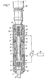
- the driving and tearing device represented in FIG. 1, comprises a central movable mass 1 which can strike, by each of its ends, either on a lower anvil 2 intended for driving, or on an upper anvil 3 intended for tearing.
- the two anvils 2 and 3 are interconnected by a shaft 4 made of non-magnetic material, passing right through the movable mass 1 through a hole 5 drilled along the axis 6 of the latter.
- the moving mass 1 is common to two electromagnetic hammers 7 and 8, arranged along the axis 6 and each produced according to French patent No. 2430827.
- the lower hammer 7 comprises a coil 9 surrounded by a shield 10; the lower neclume 2 serves as a fixed pole piece, through its cylindrical part 11 introduced inside the winding 9, while the lower end of the mass 1 serves as a mobile core for the hammer 7 also penetrating into its winding 9.
- the upper hammer 8 comprises a coil 12 surrounded by a shield 13; the upper anvil 3 serves as a fixed pole piece through its cylindrical part 14 introduced inside the coil 12, while the upper end of the mass 1 serves as a movable core for the hammer 8, also penetrating into its coil 12.
- the movable mass 1 has a flange 15, on either side of which bear, respectively, two helical springs 16 and 17 antagonistic.
- the lower spring 16 is compressed between the flange 15 and a ring 18 located above the shield 10 of the lower hammer 7, while the upper spring 17 is compressed between the flange 15 and a ring 19 placed below the shield 13 of the Tue upper level 8.
- the assembly of the two electromagnetic hammers 7 and 8 and their common mobile mass 1 is disposed under extreme housings 20 and central 21 assembled properly. To be used, this whole assembly is mounted on an external support, not shown, for example a slide with the necessary displacement means.
- the two electromagnetic hammers 7 and 8 are both connected to a common electrical supply and control system, symbolized by a block 22 and produced according to French patent No. 2,356,483 and its addition N D 2 425 302.
- a switching device 23 makes it possible to direct the current from the electrical discharge circuit to one or the other of the two windings 9 and 12.
- the operator places the switching device 23 in its position putting the babbling 9 of the lower electromagnetic hammer 7 into circuit.
- the lower end of the mobile mass 1 suspended by the springs 16 and 17 strikes the cylindrical part 11 of the lower anvil 2, the flange 24 of which presses against a stop 25.
- the lower anvil 2 transmits the kinetic energy received from the moving mass 1 to the element to be driven, fixed to the lower end of said anvil 2 by an assembly adapted to each application case.
- the operator places the switching device 23 in its other position switching on the winding 12 of the upper electromagnetic hammer 8.
- the upper end of the moving mass 1 strikes the cylindrical part 14 of the upper anvil 3, the flange 26 of which comes to rest on a corresponding stop 27.
- the upper anvil 3 transmits the kinetic energy received from the moving mass 1 to the lower anvil 2 , via the connecting shaft 4, the lower anvil 2 itself transmitting this energy to the element to be torn off.
- the length of the shaft 4 which connects the two anvils 2 and 3 together is such that, when one is in the driving position, the upper anvil 3 cannot receive the shocks in return due to the oscillation of the moving mass 1 caused by the lower hammer 7; conversely, in the tear-off position, the lower anvil 2 will not receive back impacts due to the oscillation of the moving mass 1 caused by the upper hammer 8.
- a drive in rotation of the element to be driven is obtained, in addition, by a rotation device disposed above the double electromagnetic hammer 7-8, along the axis. 6 of this double hammer.
- An electric gear motor 28, clamped on the upper cover 41 has its output shaft 29 linked in rotation with the upper anvil 3 by means of grooves allowing the axial movement of this anvil 3..
- the rotational movement is transmitted by the connecting shaft 4 to the lower anvil 2, which itself communicates it to the element to darken.
- FIG. 2 represents a second embodiment which does not differ from the first as regards the arrangement of the double electromagnetic hammer 7-8, but in which the driving in rotation of the element to be driven is obtained by a device placed laterally.
- a gear motor 30, of axis 31 parallel to the main axis 6 of the device, is clamped on a casing 32 secured to the lower part of the device.
- the output shaft 33 of the gear motor 30 carries a pinion 34, connected by an endless chain 35 to another pinion 36 machined with a housing in the form of "hexagon socket" along its axis.
- the pinion 36 is slidably mounted around the lower anvil 2, having a complementary external machining with hexagon 37, which allows the anvil 2 to rotate, therefore the element to be driven in rotation, without preventing the axial displacement of this anvil 2. All the transmission described above is housed inside the casing 32.
- the connecting shaft and the anvils can be drilled right through, the shaft in question in this case being replaced by a tube 38 and the anvils 2 and 3 having axial holes respectively 39 and 40, which extend the tube 38.
- the upper cover 41 an orifice 42 drilled along the axis 6, there is then a continuous axial passage, for the extraction and recovery of carrots at the upper part of the device, possibly for the circulation of fluids used in drilling operations.
- the driving and pulling device described above is applicable to various elements such as: piles, tubes, sheet piling, rods, etc.
- the outer end of the lower anvil 2 comprises, for the connection of these elements , means 42 adapted to each application case, for example a threaded head for screwable elements.
- means 42 adapted to each application case, for example a threaded head for screwable elements.
- the invention is more particularly applicable to the field of drilling.
- the driving and tearing device object of the invention can be, as illustrated in Figure 3, suspended from the cable 43 d 'a crane ; in this case it is advantageous to connect the cable 43 to the top of the body 44 of the device by a flexible element 45, such as a spring or block of rubber.
- a flexible element 45 such as a spring or block of rubber. The transition from driving to tearing is then done by moving the body 44 of the device relative to the anvils secured to the elements to be driven or torn off.
- This movement can be obtained by letting the body 44 of the device rest through the stop. 25 on the lower anvil 2 (see Figures 1 and 2) for driving, and pulling the body 44 upward to bring the upper anvil 3 into contact with the upper stop 27, for tearing, flexible hooking element 45 making it possible to absorb the pull-out jolts while avoiding transmitting them to the suspension cable 43.
- the upper anvil 3 has two lateral ears 46, situated outside the body 44 between the two lugs 47 for attaching the device to a cable or other suspension means.
- Two small electric jacks 48 have their bodies fixed on either side of the upper part of the body 44 of the device, while their rods 49 are connected respectively to the two ears 46, with the interposition of discs or elastic studs 50.
- This mounting has the advantage of not transmitting vibrations to the cable or other suspension means, the reversing pulse being taken up on the elements to be darkened.
Abstract
Description
La présente invention concerne un dispositif destiné au fonçage et à l'arrachement d'éléments tels que : pieux, tubes, palplanches, tiges, etc..., qui sont utilisés dans les domaines des travaux publics, des carrières,des mines et des industries de forage.The present invention relates to a device for driving and tearing off elements such as: piles, tubes, sheet piling, rods, etc., which are used in the fields of public works, quarries, mines and drilling industries.
Dans ce genre de travaux, il est nécessaire d'utiliser les vibrations et l'énergie produites par des chocs répétés, pour faire pénétrer les éléments en question dans le sol, ce que l'on désigne sous le nom de fonçage.In this kind of work, it is necessary to use the vibrations and the energy produced by repetitive shocks, to make penetrate the elements in question in the ground, what one indicates under the name of sinking.
De même, pour retirer ces éléments du sol, par arrachement, il est fréquement nécessaire d'accompagner la force de traction appliquée par l'action de chocs qui facilitent le glissement de l'élément dans le terrain.Likewise, to remove these elements from the ground, by pulling out, it is frequently necessary to accompany the tensile force applied by the action of shocks which facilitate the sliding of the element in the ground.
Dans le cas du fonçage,il est évident que l'effet des chocs doit se faire dans le sens du mouvement de pénétration, l'énergie du choc transmise à l'élément à foncer étant répartie en deux-composantes, l'une provoquant la mise en vibration de l'élément, favorisant le glissement dans le sol, l'autre composante assurant le déplacement de l'élément.In the case of driving, it is obvious that the effect of the shocks must be in the direction of the penetration movement, the energy of the shock transmitted to the element to be driven being divided into two components, one causing the vibration of the element, promoting sliding in the ground, the other component ensuring the displacement of the element.
Par exemple, dans le cas d'un fonçage vertical de pieu, la direction des chocs appliqués sera verticale et le sens des chocs orienté de haut en bas.For example, in the case of a vertical pile driving, the direction of the shocks applied will be vertical and the direction of the shocks oriented from top to bottom.
Lors de l'arrachement, les conditions seront inversées ; les chocs seront donc dirigés de bas en haut, pour obtenir l'effet désiré.During the uprooting, the conditions will be reversed; the shocks will therefore be directed from bottom to top, to obtain the desired effect.
Pour réaliser ces fonctions, l'on utilise actuellement des matériels généralement mécaniques,hydrauliques ou pneumatiques. Les appareils mécaniques sont complexes et fragiles. Quant aux appareils à fluide hydraulique ou pneumatique, leur utilisation est difficile si la température ambiante est basse. La plupart des matériels connus réalisent seulement l'une des fonctions, soit le fonçage ou l'arrachage, et il faut donc changerdlappareil pour passer d'une opération à l'autre. Même les appareils qui sont susceptibles d'assurer les deux fonctions doivent être retournés pour passer, par exemple, du fonçage à l'arrachement.To perform these functions, generally mechanical, hydraulic or pneumatic equipment is currently used. Mechanical devices are complex and fragile. As for hydraulic or pneumatic fluid devices, their use is difficult if the ambient temperature is low. Most known hardware only perform one function, either sinking or pulling, and should therefore chan ge rd the unit to switch from one operation to another. Even devices which are capable of performing both functions must be returned to pass, for example, from driving to tearing.
La présente invention vise à éliminer l'ensemble de ces inconvénients, en fournissant un appareil utilisant une source d'énergie nouvelle dans le domaine considéré, cet appareil étant de structure simple et robuste, avec un minimum de pièces en mouvement, ayant un fonctionnement non influencé par les conditions extérieures de température, et réunissant dans un ensemble compact tous les moyens nécessaires à la fois au fonçage et à l'arrachement, le passage de l'une à l'autre de ces deux opérations s'effectuant par une simple commutation, sans aucun retournement ou autre déplacement de l'appareil.The present invention aims to eliminate all of these drawbacks by providing an apparatus using a new energy source in the field considered, this apparatus being of simple and robust structure, with a minimum of moving parts, having a non-functioning influenced by external temperature conditions, and bringing together in a compact unit all the means necessary for both driving and tearing, the passage from one to the other of these two operations being effected by a simple switching , without any overturning or other movement of the device.
A cet effet, l'invention a pour objet un dispositif de fonçage et d'arrachement pour pieux, tubes, palplanches, tiges, etc., qui comprend essentiellement deux marteaux électromagnétiques superposés, disposés suivant un même axe et agissant en sens opposés, entre lesquels est montée une masse mobile oscillante commune, suspendue élastiquement, les pièces polaires respectives des deux marteaux constituant des enclumes, dont celle inférieure, frappéepar la masse mobile pour le fonçage, est munie à son extrémité extérieure de moyens permettant le raccordement des éléments à foncer ou à arracher, et dont celle supérieure, frappéepar la masse mobile pour l'arrachement, est reliée à celle inférieure par un arbre ou un tube en matériau amagnétique traversant de part en part la masse mobile par un trou foré suivant l'axe de cette dernière.To this end, the invention relates to a driving and tearing device for piles, tubes, sheet piles, rods, etc., which essentially comprises two superimposed electromagnetic hammers, arranged along the same axis and acting in opposite directions, between which is mounted a common oscillating mobile mass, suspended elastically, the respective pole pieces of the two hammers constituting anvils, of which the lower one, struck by the mobile mass for driving, is provided at its outer end with means allowing the connection of the elements to be driven or to be torn off, and the upper one, struck by the moving mass for tearing, is connected to the lower one by a shaft or a tube made of non-magnetic material passing right through the moving mass by a hole drilled along the axis of this last.
On réunit ainsi, dans un ensemble de forme générale cylindrique allongée, un système de fonçage et un système d'arrachement qui fonctionnent à partir de l'énergie électrique et qui utilisent une masse mobile frappante commune, dont les extrémités peuvent pénétrer respectivement dans les bobinages des deux marteaux électromagnétiques pour en constituer les noyaux mobiles, cette masse mobile étant suspendue par exemple entre deux ressorts antagonistes lui permettant d'osciller de part et d'autre d'une position de repos.Thus, in a generally cylindrical elongated assembly, a driving system and a tearing system which operate on the basis of electrical energy and which use a common striking moving mass, the ends of which can penetrate respectively into the windings two electromagnetic hammers to form its mobile cores, this mobile mass being suspended for example between two opposing springs allowing it to oscillate on either side of a rest position.
Etant donné que les deux marteaux électromagnétiques du dispositif objet de l'invention sont utilisés alternativement, l'un servant au fonçage et l'autre à l'arrachement, et n'entrent jamais en service simultanément, ces deux marteaux sont avantageusement reliés à un système électrique commun d'alimentation et de commande, par l'intermédiaire d'un commutateur permettant de diriger à volonté des impulsions de courant vers le bobinage de l'un des marteaux pour le fonçage ou vers le bobinage de l'autre marteau pour l'arrachement de l'élément raccordé à l'enclume inférieure. On comprend que, pour l'arrachement, la masse mobile attirée par le bobinage supérieur vient frapper l'enclume correspondante,laquelle transmet l'énergie reçue à l'enclume inférieure par l'intermédiaire de l'arbre ou du tube-de liaison, tandis que pour le fonçage la masse mobile, attirée par le bobinage inférieur, frappe directement l'enclume à laquelle sont raccordés les éléments à foncer.Since the two electromagnetic hammers of the device object of the invention are used alternately, one used for driving and the other for tearing, and never enter service simultaneously, these two hammers are advantageously connected to a common electrical supply and control system, by means of a switch making it possible to direct current pulses at will to the winding of one of the hammers for driving or to the winding of the other hammer for driving 'tearing of the element connected to the lower anvil. It is understood that, for tearing, the mobile mass attracted by the upper winding strikes the corresponding anvil, which transmits the energy received to the lower anvil via the shaft or the connecting tube, while for driving the moving mass, attracted by the lower winding, directly strikes the anvil to which the elements to be driven are connected.
Une rotation de ces éléments peut être nécessaire, en combinaison avec les chocs. Cette rotation peut être obtenue soit en entraînant l'enclume supérieure soit en entraînant l'enclume inférieure, notamment avec les dispositions suivantes :
- - Suivant une première forme de réalisation, le dispositif comprend, pour l'entraînement en rotation de l'élément à foncer, un moto-réducteur électrique disposé suivant l'axe du double marteau électromagnétique et accouplé, par l'intermédiaire d'un arbre de sortie cannelé, à l'enclume supérieure, le mouvement de rotation étant transmis par l'arbre ou le tube de liaison à l'enclume inférieure.
- - Suivant une seconde forme de réalisation, le dispositif comprend, pour l'entraînement en rotation de l'élément à foncer, un moto-réducteur électrique placé latéralement, par rapport à l'axe du double marteau électromagnétique, et ayant son arbre de sortie relié, par l'intermédiaire d'une transmission telle qu'à chaîne sans fin, à un élément rotatif creux monté coulissant autour d'une partie de profil extérieur correspondant de l'enclume inférieure.
- - According to a first embodiment, the device comprises, for the rotational drive of the element to be driven, an electric geared motor arranged along the axis of the double electromagnetic hammer and coupled, via a shaft splined outlet, to the upper anvil, the rotational movement being transmitted by the shaft or the connecting tube to the lower anvil.
- - According to a second embodiment, the device comprises, for driving the element to be driven in rotation, an electric geared motor placed laterally, with respect to the axis of the double electromagnetic hammer, and having its output shaft connected, via a transmission such as an endless chain, to a hollow rotary element slidably mounted around a part of the corresponding external profile of the lower anvil.
Pour certaines opérations, nécessitant en outre l'évacuation de carottes ou la circulation de fluides de forage l'élément de liaison entre les deux enclumes,qui traverse de part en part la masse mobile, est un tube prolongé par des perçages axiaux ménagés respectivement dans les deux enclumes, pour constituer un passage axial continu.For certain operations, further requiring the evacuation of cores or the circulation of drilling fluids, the connecting element between the two anvils, which passes right through the moving mass, is a tube extended by axial bores provided respectively in the two anvils, to constitute a continuous axial passage.
Cette dernière caractéristique est compatible avec la présence de moyens d'entraînement en rotation mais dans ce cas, afin de permettre la récupération des carottes ou l'arrivée du fluide de forage, on choisira de préférence pour les dits moyens d'entraînement en rotation la disposition latérale définie plus haut, de manière à libérer la partie supérieure de l'appareil.This last characteristic is compatible with the presence of rotational drive means but in this case, in order to allow the recovery of the cores or the arrival of the drilling fluid, it will preferably be chosen for the said rotational drive means the lateral arrangement defined above, so as to free the upper part of the apparatus.
De toute façon, l'invention sera bien comprise à l'aide de la description qui suit, en référence au dessin schématique annexé représentant, à titre d'exemples non limitatifs, des formes d'exécution de ce dispositif de fonçage et d'arrachement pour pieux, tubes, palplanches, tiges, etc. :
- Figure 1 est une vue en coupe longitudinale d'un premier dispositif de fonçage et d'arrachement conforme à l'invention, avec des moyens d'entraînement en rotation disposés suivant l'axe du double marteau électromagnétique ;
- Figure 2 est une vue en coupe longitudinale d'un second dispositif de fonçage et d'arrachement conforme à l'invention, avec des moyens d'entraînement en rotation placés latéralement, par rapport à l'axe du double marteau électromagnétique ;
- Figure 3 est une vue de côté de la partie supérieure d'un dispositif de fonçage et d'arrachement conforme à l'invention, sans moyens d'entraînement en rotation et suspendu à un câble ;
- Figure 4 est une vue de côté, avec coupes partielles, de la partie supérieure d'un dispositif de fonçage et d'arrachement constituant une variante du dispositif de la figure 3 ;
- Figure 5 est une vue en plan par dessus du dispositif de la figure 4.
- Figure 1 is a longitudinal sectional view of a first driving and tearing device according to the invention, with rotational drive means arranged along the axis of the double electromagnetic hammer;
- Figure 2 is a longitudinal sectional view of a second driving and tearing device according to the invention, with rotation drive means placed laterally, relative to the axis of the double electromagnetic hammer;
- Figure 3 is a side view of the upper part of a driving and tearing device according to the invention, without rotary drive means and suspended from a cable;
- Figure 4 is a side view, with partial sections, of the upper part of a driving and tearing device constituting a variant of the device of FIG. 3;
- Figure 5 is a plan view from above of the device of Figure 4.
Le dispositif de fonçage et d'arrachement, représenté sur la figure 1, comprend une masse mobile centrale 1 pouvant frapper, par chacune de ses extrémités, soit sur une enclume inférieure 2 destinée au fonçage, soit sur une enclume supérieure 3 destinée à l'arrachement. Les deux enclumes 2 et 3 sont reliées entre elles par un arbre 4 en matériau amagnétique, traversant de part en part la masse mobile 1 par un trou 5 foré suivant l'axe 6 de cette dernière.The driving and tearing device, represented in FIG. 1, comprises a central
La masse mobile 1 est commune à deux marteaux électromagnétiques 7 et 8, disposés suivant l'axe 6 et réalisés chacun suivant le brevet français N° 2430827. Le marteau inférieur 7 comprend un bobinage 9 entouré d'un blindage 10 ; l'neclume inférieure 2 lui sert de pièce polaire fixe, par sa partie cylindrique 11 introduite à l'intérieur-du bobinage 9, tandis que l'extrémité inférieure de la masse 1 sert de noyau mobile au marteau 7 en pénétrant aussi dans son bobinage 9. D'une manière symétrique, le marteau supérieur 8 comprend un bobinage 12 entouré d'un blindage 13 ; l'enclume supérieure 3 lui sert de pièce polaire fixe par sa partie cylindrique 14 introduite à l'intérieur du bobinage 12, tandis que l'extrémité supérieure de la masse 1 sert de noyau mobile au marteau 8 en pénétrant aussi dans son bobinage 12.The moving
Dans sa partie centrale, la masse mobile 1 présente une collerette 15, de part et d'autre de laquelle prennent appui, respectivement, deux ressorts hélicolcaux 16 et 17 antagonistes. Le ressort inférieur 16 est comprimé entre la collerette 15 et une bague 18 située au-dessus du blindage 10 du marteau inférieur 7, tandis que le ressort supérieur 17 est comprimé entre la collerette 15 et une bague 19 placée au-dessous du blindage 13 du marteau supérieur 8.In its central part, the
L'ensemble des deux marteaux électromagnétiques 7 et 8 et de leur masse mobile commune 1 est disposé sous des carters extrêmes 20 et central 21 assemblés convenablement. Pour être utilisé, tout cet ensemble est monté sur un support extérieur non représenté, par exemple une glissière avec les moyens de déplacement nécessaires.The assembly of the two
Les deux marteaux électromagnétiques 7 et 8 sont reliés, l'un et l'autre, à un système électrique commun d'alimentation et de commande, symbolisé par un bloc 22 et réalisé suivant le brevet français N° 2 356 483 et son addition ND 2 425 302. Un dispositif de commutation 23 permet de diriger le courant issu du circuit électrique de décharge vers l'un ou l'autre des deux bobinages 9 et 12.The two
Pour obtenir le fonçage, l'opérateur place le dispositif de commutation 23 dans sa position mettant en circuit le babinage 9 du marteau électromagnétique inférieur 7. A chaque impulsion de courant envoyée dans ce bobinage 9, l'extrémité inférieure de la masse mobile 1 suspendue par les ressorts 16 et 17, vient frapper la partie cylindrique 11 de l'enclume inférieure 2, dont la collerette 24 vient appuyer sur une butée 25. L'enclume inférieure 2 transmet l'énergie cinétique reçue de la masse mobile 1 à l'élément à fonçer, fixé à l'extrémité inférieure de ladite enclume 2 par un montage adapté à chaque cas d'application.To obtain driving, the operator places the
Pour obtenir l'arrachement, l'opérateur place le dispositif de commutation 23 dans son autre position mettant en circuit le bobinage 12 du marteau électromagnétique supérieur 8. A chaque impulsion de courant envoyée dans ce bobinage 12, l'extrémité supérieure de la masse mobile 1 vient frapper la partie cylindrique 14 de l'enclume supérieure 3, dont la collerette 26 vient s'arrêter sur une butée correspondante 27. L'enclume supérieure 3 transmet l'énergie cinétique reçue de la masse mobile 1 à l'enclume inférieure 2, par l'intermédiaire de l'arbre de liaison 4, l'enclume inférieure 2 transmettant elle-même cette énergie à l'élément à arracher.To obtain the breakout, the operator places the
La longueur de l'arbre 4 qui relie entre elles les deux enclumes 2 et 3 est telle que, lorsqu'on se trouve en position de fonçage, l'enclume supérieure 3 ne peut recevoir les chocs en retour dus à l'oscillation de la masse mobile 1 provoquée par le marteau inférieur 7 ; inversement, en position d'arrachement, l'enclume inférieure 2 ne recevra pas les chocs en retour dus à l'oscillation de la masse mobile 1 provoquée par le marteau supérieur 8.The length of the
Dans la première forme d'exécution représentée sur la figure 1, un entraînement en rotation de l'élément à foncer est obtenu, en outre, par un dispositif de rotation disposé au-dessus du double marteau électromagnétique 7-8, suivant l'axe 6 de ce double marteau. Un moto-réducteur électrique 28, bridé sur le couvercle supérieur 41, a son arbre de sortie 29 lié en rotation avec l'enclume supérieure 3 par l'intermédiaire de cannelures permettant le déplacement axial de cette enclume 3..Le mouvement de rotation est transmis par l'arbre de liaison 4 à l'enclume inférieure 2, qui elle-même la communique à l'élément à foncer.In the first embodiment shown in FIG. 1, a drive in rotation of the element to be driven is obtained, in addition, by a rotation device disposed above the double electromagnetic hammer 7-8, along the axis. 6 of this double hammer. An
La figure 2 représente une seconde forme d'exécution qui ne diffère pas de la première en ce qui concerne la disposition du double marteau électromagnétique 7-8, mais dans laquelle l'entraînement en rotation de l'élément à foncer est obtenu par un dispositif placé latéralement. Un moto-réducteur 30,d'axe 31 parallèle à l'axe principal 6 de l'appareil, est bridé sur un carter 32 solidaire de la partie inférieure de l'appareil. L'arbre de sortie 33 du moto-réducteur 30 porte un pignon 34, relié par une chaîne sans fin 35 à un autre pignon 36 usiné avec un logement en forme de "six pans creux" suivant son axe. Le pignon 36 est monté coulissant autour de l'enclume inférieure 2, possèdant un usinage extérieur complémentaire à six pans 37, ce qui permet l'entraînement en rotation de l'enclume 2, donc de l'élément à foncer, sans empêcher le déplacement axial de cette enclume 2. Toute la transmission précédemment décrite est logée à l'intérieur du carter 32.FIG. 2 represents a second embodiment which does not differ from the first as regards the arrangement of the double electromagnetic hammer 7-8, but in which the driving in rotation of the element to be driven is obtained by a device placed laterally. A
Comme le montre encore la figure 2, l'arbre de liaison et les enclumes peuvent être forés de part en part, l'arbre en question étant dans ce cas remplacé par un tube 38 et les enclumes 2 et 3 comportant des perçages axiaux respectivement 39 et 40, qui prolongent le tube 38. En prévoyant aussi sur le couvercle supérieur 41 un orifice 42 percé suivant l'axe 6, on dispose alors d'un passage axial continu, pour l'extraction et la récupération de carottes à la partie supérieure du dispositif, éventuellement pour la circulation de fluides utilisés dans les opérations de forage.As still shown in FIG. 2, the connecting shaft and the anvils can be drilled right through, the shaft in question in this case being replaced by a
Le dispositif de fonçage et d'arrachement précédemment décrit est applicable à des éléments divers tels que : pieux, tubes, palplanches, tiges, etc....L'extrémité extérieure de l'enclume inférieure 2 comporte, pour le raccordement de ces éléments, des moyens 42 adaptés à chaque cas d'application, par exemple une tête filetée pour des éléments vissables. Dans le cas où sont prévus des moyens pour l'entraînement en rotation des éléments en question, l'invention est plus particulièrement applicable au domaine du forage.The driving and pulling device described above is applicable to various elements such as: piles, tubes, sheet piling, rods, etc. The outer end of the
Dans le cas inverse où le double marteau électromagnétique est utilisé seul, sans moyens d'entraînement en rotation, le dispositif de fonçage et d'arrachement objet de l'invention peut être, comme l'illustre la figure 3, suspendu au câble 43 d'une grue ; dans ce cas il est avantageux de relier le câble 43 au sommet du corps 44 du dispositif par un élément souple 45, tel que ressort ou bloc de caoutchouc. Le passage du fonçage à l'arrachement se fait alors en déplaçant le corps 44 du dispositif par rapport aux enclumes solidaires des éléments à foncer ou à arracher.In the opposite case where the double electromagnetic hammer is used alone, without rotary drive means, the driving and tearing device object of the invention can be, as illustrated in Figure 3, suspended from the cable 43 d 'a crane ; in this case it is advantageous to connect the
Ce déplacement peut être obtenu en laissant reposer le corps 44 du dispositif par l'intermédiaire de la butée basse 25 sur l'enclume inférieure 2 (voir figures 1 et 2) pour le fonçage, et en tirant le corps 44 vers le haut pour amener l'enclume supérieure 3 en contact avec la butée haute 27, pour l'arrachement, l'élément souple d'accrochage 45 permettant d'absorber les à-coups à l'arrachement en évitant de les transmettre au câble de suspension 43.This movement can be obtained by letting the
Dans une variante, représentée sur les figures 4 et 5, l'enclume supérieure 3 possède deux oreilles latérales 46, situées à l'extérieur du corps 44 entre les deux pattes d'accrochage 47 du dispositif à un câble ou autre moyen de suspension.Deux petits vérins électriques 48 ont leurs corps fixés de part et d'autre de la partie supérieure du corps 44 du dispositif, tandis que leurs tiges 49 sont reliées respectivement aux deux oreilles 46, avec interposition de disques ou plots élastiques 50. Ce montage a l'avantage de ne pas transmettre de vibrations au câble ou autre moyen de suspension, l'impulsion de recul étant reprise sur les éléments à foncer.In a variant, shown in FIGS. 4 and 5, the
Comme il va de soi, l'invention ne se limite pas aux seules formes d'exécution de ce dispositif de fonçage et d'arrachement qui ont été décrites ci-dessus, à titre d'exemples ; elle en embrasse, au contraire, toutes les variantes de réalisation et d'application conçues suivant les mêmes principes.It goes without saying that the invention is not limited to the sole embodiments of this driving and tearing device which have been described above, by way of examples; on the contrary, it embraces all of the variant embodiments and applications designed according to the same principles.
Claims (6)
Priority Applications (1)
| Application Number | Priority Date | Filing Date | Title |
|---|---|---|---|
| AT82420120T ATE13451T1 (en) | 1981-10-02 | 1982-08-24 | DEVICE FOR DRIVING AND EXTRACTING PILES, PIPES, SHEET PILING, BARS, ETC. |
Applications Claiming Priority (2)
| Application Number | Priority Date | Filing Date | Title |
|---|---|---|---|
| FR8119118 | 1981-10-02 | ||
| FR8119118A FR2514049A1 (en) | 1981-10-02 | 1981-10-02 | DEVICE FOR LANDING AND ARRACTING FOR PILES, TUBES, PALPLANCHES, RODS, ETC. |
Publications (2)
| Publication Number | Publication Date |
|---|---|
| EP0076768A1 true EP0076768A1 (en) | 1983-04-13 |
| EP0076768B1 EP0076768B1 (en) | 1985-05-22 |
Family
ID=9262929
Family Applications (1)
| Application Number | Title | Priority Date | Filing Date |
|---|---|---|---|
| EP82420120A Expired EP0076768B1 (en) | 1981-10-02 | 1982-08-24 | Apparatus for driving and drawing piles, tubes, sheet pilings, stakes, etc. |
Country Status (7)
| Country | Link |
|---|---|
| US (1) | US4468594A (en) |
| EP (1) | EP0076768B1 (en) |
| JP (1) | JPS5869929A (en) |
| AT (1) | ATE13451T1 (en) |
| CA (1) | CA1204729A (en) |
| DE (1) | DE3263759D1 (en) |
| FR (1) | FR2514049A1 (en) |
Cited By (2)
| Publication number | Priority date | Publication date | Assignee | Title |
|---|---|---|---|---|
| EP0648582A1 (en) * | 1993-10-19 | 1995-04-19 | Yamada Juki Co., Ltd. | Rotary impacting apparatus |
| CN111287183A (en) * | 2020-03-27 | 2020-06-16 | 安徽一诺青春工业设计有限公司 | Road construction's pile device |
Families Citing this family (15)
| Publication number | Priority date | Publication date | Assignee | Title |
|---|---|---|---|---|
| US4799557A (en) * | 1985-04-29 | 1989-01-24 | Martelec - Societe Civile Particuliere | Electromagnetic pile driver |
| FR2581100B1 (en) * | 1985-04-29 | 1987-10-09 | Martelec | ELECTRO-MAGNETIC HATCHING SHEEP |
| US5280673A (en) * | 1992-02-21 | 1994-01-25 | Electroimpact, Inc. | Electromagnetic bolt insertion system |
| US5241292A (en) * | 1992-05-28 | 1993-08-31 | Prime Mover, Inc. | Three position electrically operated actuator |
| DE4343589C1 (en) * | 1993-12-21 | 1995-04-27 | Klemm Guenter | Fluid operated hammer |
| FR2765904B1 (en) | 1997-07-08 | 1999-10-08 | Jacques Demichelis | ELECTROMAGNETIC HAMMER WITH MOBILE FERROMAGNETIC MASS |
| FR2802949B1 (en) | 1999-12-22 | 2002-09-27 | Durmeyer Entrp Travaux Publics | ELECTROMAGNETIC HAMMER WITH MOBILE FERROMAGNETIC MASS |
| DE10025371A1 (en) * | 2000-05-23 | 2001-11-29 | Hilti Ag | Hand tool with electromagnetic striking mechanism |
| FR2837412A1 (en) * | 2002-03-22 | 2003-09-26 | Technifor | SUCCESSIVE PERCUSSION HOLLOW MARKING DEVICE |
| US6695070B1 (en) * | 2002-08-05 | 2004-02-24 | Matsushita Electric Works, Ltd. | Magnetic impact device and method for magnetically generating impact motion |
| NZ528332A (en) * | 2003-09-22 | 2006-04-28 | Ramet Holdings Ltd | Impact driver for driving poles, piles or posts including linear induction motor |
| US10149711B2 (en) | 2012-03-30 | 2018-12-11 | Depuy Mitek, Llc | Surgical impact tool |
| EP4147655A1 (en) | 2016-08-31 | 2023-03-15 | DePuy Synthes Products, Inc. | Orthopedic impacting device having a launched mass delivering a controlled, repeatable & reversible impacting force |
| US11083512B2 (en) | 2016-08-31 | 2021-08-10 | DePuy Synthes Products, Inc. | Orthopedic device delivering a controlled, repeatable impact |
| DE102018209564B4 (en) * | 2018-06-14 | 2021-05-20 | Krinner Innovation Gmbh | SCREW-IN DEVICE WITH IMPACT EFFECT |
Citations (3)
| Publication number | Priority date | Publication date | Assignee | Title |
|---|---|---|---|---|
| FR25277E (en) * | 1919-07-10 | 1923-01-23 | Reinforced concrete screw piles for foundations | |
| FR1107275A (en) * | 1953-06-18 | 1955-12-29 | Metallwarenfabrik Markdorf Joh | Electrically operated device for axially moving tools |
| GB1125853A (en) * | 1967-01-16 | 1968-09-05 | Marutai Doboku Company Ltd | A pile driving apparatus including earth boring equipment |
Family Cites Families (6)
| Publication number | Priority date | Publication date | Assignee | Title |
|---|---|---|---|---|
| US1753454A (en) * | 1925-03-30 | 1930-04-08 | Central Electric Tool Company | Electric percussive tool |
| US2241364A (en) * | 1938-01-22 | 1941-05-06 | Hulbert Clinton Horace | Electromagnetic hammer |
| GB821164A (en) * | 1956-09-10 | |||
| FR2085507A1 (en) * | 1970-04-28 | 1971-12-24 | Drye Lucien | |
| FR2356483A1 (en) * | 1976-06-28 | 1978-01-27 | Jacquemet Georges | ELECTRO-MAGNETIC PERCUSSION DEVICE |
| JPS5645385A (en) * | 1979-09-18 | 1981-04-25 | Hideaki Kishida | Electromagnetic hammer |
-
1981
- 1981-10-02 FR FR8119118A patent/FR2514049A1/en active Granted
-
1982
- 1982-08-24 AT AT82420120T patent/ATE13451T1/en active
- 1982-08-24 EP EP82420120A patent/EP0076768B1/en not_active Expired
- 1982-08-24 DE DE8282420120T patent/DE3263759D1/en not_active Expired
- 1982-09-07 CA CA000410875A patent/CA1204729A/en not_active Expired
- 1982-09-24 US US06/423,082 patent/US4468594A/en not_active Expired - Fee Related
- 1982-10-01 JP JP57171069A patent/JPS5869929A/en active Granted
Patent Citations (3)
| Publication number | Priority date | Publication date | Assignee | Title |
|---|---|---|---|---|
| FR25277E (en) * | 1919-07-10 | 1923-01-23 | Reinforced concrete screw piles for foundations | |
| FR1107275A (en) * | 1953-06-18 | 1955-12-29 | Metallwarenfabrik Markdorf Joh | Electrically operated device for axially moving tools |
| GB1125853A (en) * | 1967-01-16 | 1968-09-05 | Marutai Doboku Company Ltd | A pile driving apparatus including earth boring equipment |
Cited By (3)
| Publication number | Priority date | Publication date | Assignee | Title |
|---|---|---|---|---|
| EP0648582A1 (en) * | 1993-10-19 | 1995-04-19 | Yamada Juki Co., Ltd. | Rotary impacting apparatus |
| US5488997A (en) * | 1993-10-19 | 1996-02-06 | Yamada Juki Co., Ltd. | Rotary impacting apparatus |
| CN111287183A (en) * | 2020-03-27 | 2020-06-16 | 安徽一诺青春工业设计有限公司 | Road construction's pile device |
Also Published As
| Publication number | Publication date |
|---|---|
| DE3263759D1 (en) | 1985-06-27 |
| JPH0354211B2 (en) | 1991-08-19 |
| JPS5869929A (en) | 1983-04-26 |
| US4468594A (en) | 1984-08-28 |
| FR2514049A1 (en) | 1983-04-08 |
| CA1204729A (en) | 1986-05-20 |
| FR2514049B1 (en) | 1984-01-13 |
| EP0076768B1 (en) | 1985-05-22 |
| ATE13451T1 (en) | 1985-06-15 |
Similar Documents
| Publication | Publication Date | Title |
|---|---|---|
| EP0076768B1 (en) | Apparatus for driving and drawing piles, tubes, sheet pilings, stakes, etc. | |
| EP0399122B1 (en) | Anti-rebounce apparatus for avoiding multiple impacts of a mass after a first impact against another element | |
| FR2601397A1 (en) | METHOD AND TOWING DEVICE FOR PRESSING TOOLS IN THE SOIL | |
| EP0002160B1 (en) | Device for drilling boreholes in the soil | |
| CA1192989A (en) | Device for preventing multiple rebounds of a mass dropped in a straight line on a target surface | |
| CA1221158A (en) | Device for generating seismic waves within a well, using a free falling weight dropped on a fixed target | |
| FR2646241A1 (en) | ANTI-REBOUND DEVICE FOR A MASS COMING TO STRIKE A TARGET MEMBER | |
| EP3168396A1 (en) | Locking device for sliding gate, and associated sliding gate | |
| EP0203003A1 (en) | Remotely-controlled assembling device for two items | |
| FR2502663A1 (en) | DEVICE FOR PUSHING OR EXTRACTING PILING | |
| US2927773A (en) | Impact driver for well points and the like | |
| EP1180576A1 (en) | Control device for actuating a blind | |
| EP0168306B1 (en) | Bistable reversing device, especially for feeding an oxygen circuit in an airplane, and its application | |
| CA2415359A1 (en) | Percussion hydraulic apparatus | |
| FR2482728A1 (en) | Probe appts. for inspecting tube plate in heat exchanger - esp. for detecting defects in steam generator in pressurised water nuclear reactor | |
| CN111122216A (en) | Planet surface selectable point sampler | |
| FR2698944A1 (en) | Gear motor. | |
| EP0210092B1 (en) | Moving device working in a stepwise manner | |
| EP3023562A1 (en) | Door actuating device with electric locking | |
| EP3339673B1 (en) | Device for guiding a spring in a control mechanism and electrical protection apparatus comprising same | |
| FR2830611A1 (en) | Shooting practice target is mounted on carriage moving to and fro along rail and turning at each end | |
| EP0088168A2 (en) | Safety device for the load-engaging mechanism of nuclear combustion elements | |
| FR2581337A1 (en) | Improvements to jack hammers | |
| SU1596083A1 (en) | Device for monitoring activation of downhole perforator | |
| EP0797230A1 (en) | Remote control with geared motor unit with a centrifugal clutch |
Legal Events
| Date | Code | Title | Description |
|---|---|---|---|
| PUAI | Public reference made under article 153(3) epc to a published international application that has entered the european phase |
Free format text: ORIGINAL CODE: 0009012 |
|
| AK | Designated contracting states |
Designated state(s): AT BE CH DE GB IT LI LU NL SE |
|
| 17P | Request for examination filed |
Effective date: 19830921 |
|
| ITF | It: translation for a ep patent filed |
Owner name: JACOBACCI & PERANI S.P.A. |
|
| GRAA | (expected) grant |
Free format text: ORIGINAL CODE: 0009210 |
|
| AK | Designated contracting states |
Designated state(s): AT BE CH DE GB IT LI LU NL SE |
|
| PG25 | Lapsed in a contracting state [announced via postgrant information from national office to epo] |
Ref country code: NL Effective date: 19850522 Ref country code: AT Effective date: 19850522 |
|
| REF | Corresponds to: |
Ref document number: 13451 Country of ref document: AT Date of ref document: 19850615 Kind code of ref document: T |
|
| REF | Corresponds to: |
Ref document number: 3263759 Country of ref document: DE Date of ref document: 19850627 |
|
| PG25 | Lapsed in a contracting state [announced via postgrant information from national office to epo] |
Ref country code: LU Free format text: LAPSE BECAUSE OF NON-PAYMENT OF DUE FEES Effective date: 19850831 Ref country code: LI Effective date: 19850831 Ref country code: CH Effective date: 19850831 |
|
| NLV1 | Nl: lapsed or annulled due to failure to fulfill the requirements of art. 29p and 29m of the patents act | ||
| PLBE | No opposition filed within time limit |
Free format text: ORIGINAL CODE: 0009261 |
|
| STAA | Information on the status of an ep patent application or granted ep patent |
Free format text: STATUS: NO OPPOSITION FILED WITHIN TIME LIMIT |
|
| REG | Reference to a national code |
Ref country code: CH Ref legal event code: PL |
|
| 26N | No opposition filed | ||
| BERE | Be: lapsed |
Owner name: MARTELEC Effective date: 19860831 |
|
| PG25 | Lapsed in a contracting state [announced via postgrant information from national office to epo] |
Ref country code: BE Effective date: 19890831 |
|
| PGFP | Annual fee paid to national office [announced via postgrant information from national office to epo] |
Ref country code: SE Payment date: 19910731 Year of fee payment: 10 |
|
| ITTA | It: last paid annual fee | ||
| PGFP | Annual fee paid to national office [announced via postgrant information from national office to epo] |
Ref country code: GB Payment date: 19920804 Year of fee payment: 11 |
|
| PGFP | Annual fee paid to national office [announced via postgrant information from national office to epo] |
Ref country code: DE Payment date: 19920805 Year of fee payment: 11 |
|
| PG25 | Lapsed in a contracting state [announced via postgrant information from national office to epo] |
Ref country code: SE Effective date: 19920825 |
|
| PG25 | Lapsed in a contracting state [announced via postgrant information from national office to epo] |
Ref country code: GB Effective date: 19930824 |
|
| GBPC | Gb: european patent ceased through non-payment of renewal fee |
Effective date: 19930824 |
|
| PG25 | Lapsed in a contracting state [announced via postgrant information from national office to epo] |
Ref country code: DE Effective date: 19940503 |
|
| EUG | Se: european patent has lapsed |
Ref document number: 82420120.6 Effective date: 19930307 |