EP0076306B1 - Passive temperature control arrangement for fluid flow stream sensor heater - Google Patents
Passive temperature control arrangement for fluid flow stream sensor heater Download PDFInfo
- Publication number
- EP0076306B1 EP0076306B1 EP82901393A EP82901393A EP0076306B1 EP 0076306 B1 EP0076306 B1 EP 0076306B1 EP 82901393 A EP82901393 A EP 82901393A EP 82901393 A EP82901393 A EP 82901393A EP 0076306 B1 EP0076306 B1 EP 0076306B1
- Authority
- EP
- European Patent Office
- Prior art keywords
- heating means
- sensor
- resistive heater
- ptc
- heater
- Prior art date
- Legal status (The legal status is an assumption and is not a legal conclusion. Google has not performed a legal analysis and makes no representation as to the accuracy of the status listed.)
- Expired
Links
Images
Classifications
-
- G—PHYSICS
- G01—MEASURING; TESTING
- G01P—MEASURING LINEAR OR ANGULAR SPEED, ACCELERATION, DECELERATION, OR SHOCK; INDICATING PRESENCE, ABSENCE, OR DIRECTION, OF MOVEMENT
- G01P5/00—Measuring speed of fluids, e.g. of air stream; Measuring speed of bodies relative to fluids, e.g. of ship, of aircraft
- G01P5/14—Measuring speed of fluids, e.g. of air stream; Measuring speed of bodies relative to fluids, e.g. of ship, of aircraft by measuring differences of pressure in the fluid
- G01P5/16—Measuring speed of fluids, e.g. of air stream; Measuring speed of bodies relative to fluids, e.g. of ship, of aircraft by measuring differences of pressure in the fluid using Pitot tubes, e.g. Machmeter
- G01P5/165—Arrangements or constructions of Pitot tubes
Definitions
- This invention relates to a heated fluid flow stream data sensor.
- resistance heating means is used to denote an electrical heating means which does not substantially change in resistance over its range of operating temperatures
- positive temperature coefficient heating means or “PTC heating means” is used to denote an electrical heating means which increases in resistance a substantial amount at a temperature within its normal range of operating temperatures.
- resistive heaters typically constructed of Ni-Cr (nickel-chromium) alloy.
- the maximum rated power of the heater must be such that sufficient heat for satisfactory performance of the sensor under the most severe icing conditions is supplied.
- Such heaters are typically automatically energized when the aircraft is operating on internal power. The heater then operates continually at maximum rated power. The result is that while the aircraft is on the ground, which is the condition of minimum heat dissipation from the sensor, the heater causes inordinately high temperatures in the sensor. Temperatures of 550°C are not uncommon.
- Such temperatures may result in burn out of the heater and also contribute to erosion of the probe features due to impingement of salt in the air-stream when airborne at low altitude, both of which affect the accuracy of the instrument. Such temperatures also contribute to the creation of a safety hazard. Accordingly, it is desirable to provide a heater power control system that will continuously vary heater power in response to rate of heat dissipation being experienced at the external surface of the sensor. In order to preserve the reliability of the sensor system, it is desirable that the heater power control system be passive as opposed to an active electronic system.
- a heated fluid flow stream data sensor and in particular a flow sonde for an air vehicle, comprising a probe and support means therefor both for mounting in a fluid flow stream, the probe including sensing means operative in use to sense at least one parameter of the fluid flow stream, and heating means associated with the sensor to provide heating thereof.
- the heating means is resistance heating means while in US-A--4000647 the heating means is provided by a plurality of thermally controlled resistance means.
- a sensor as set out above is characterised in that the heating means comprises electrical resistance heating means disposed on the probe, and electrical positive temperature coefficient heating means disposed on and in thermally conductive relationship with the external surface of the sensor and electrically connected in series with the resistance heating means, the positive temperature coefficient heating means providing in use analog control of the output of both the positive temperature coefficient heating means and the resistance heating means over a range of heat dissipation values for the sensor.
- the present invention makes use of the properties of the two types of heating means used co-operatively, to provide a sensor which is heated as required under all operating conditions.
- the high rate of heat dissipation will cool the PTC heating means.
- Such cooling causes its resistance to drop toward its minimum value (R m;n ).
- the resistance of the conventional resistance heating means is selected to be approximately equal to Rmin of the PTC heating means.
- the range of resistance values for Rmin and the resistance of the conventional resistance heating means is typically 8 to 20 ohms. In this condition, total circuit resistance is at its minimum value and current is at its maximum value, resulting.in the maximum power dissipation from the circuit.
- the resistance versus temperature characteristic of the PTC heating means causes the power of the circuit to vary in an analog manner between the aforementioned extremes responsive to the amount of heat being dissipated at the external surface.
- the nature of this positive temperature coefficient of resistance characteristic of the heating means is to seek to maintain itself at a certain temperature called the anomaly or Curie temperature (T a ).
- T a Curie temperature
- an increased rate of heat dissipation results in an increase in total circuit power dissipation.
- a reduced rate of heat dissipation results in a reduction in demand for circuit power dissipation.
- the resistive material preferably used for the PTC heating means is doped barium titanate, a well known ceramic material that displays rather abrupt positive temperature coefficient properties characterised by a large change in resistance through a narrow band of temperature about T. and which is used widely in other applications.
- an electric iron utilising a series arrangement of a conventional resistance heating means and a PTC heating means, operative to control the temperature of the iron under difficult conditions of use.
- FR-A-2456905 there is disclosed a fuel nozzle having a conventional resistance heating means mounted thereon and a PTC heating means mounted in the supply pipe to the nozzle, the two heating means operating together to control the temperature of a liquid passing through the nozzle, particularly to prevent overheating.
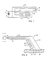
- the circuit 8 shown in Figure 1 includes terminals 10 and 12 coupled to an external conventional power source 11, which may be either an AC or a DC supply.
- Terminal 12 is coupled by a line 13 to PTC resistive heater 14, which in turn is coupled by a line 15 to one end of a conventional resistance heater 16.
- a second end of conventional heater 16 is coupled by a line 17 to terminal 10, thereby forming a series cirguit.
- Conventional resistive heater 16 is preferably formed from a Ni-Cr (Nickel-Chromium) alloy.
- the PTC resistive heater 14 is preferably constructed with a ceramic body of barium titanate material, which material has the characteristic of abruptly changing its value of resistance from a low value to a high value through a narrow band of temperature increase. Such resistive materials are disclosed in the prior art.
- FIG. 1 additionally shows second conventional resistive heater 18.
- such heater is located proximate to conventional resistive heater 16 to provide supplemental heating.
- second conventional resistive heater 18 is coupled at one end to line 13 and at a second end to line 15.
- heater 18 is connected in the heater circuit in a parallel electrical relationship with PTC resistive heater 14. It is understood that second conventional resistive heater 18 could also be powered from a source independent from that powering the instant heater circuit and is then electrically independent from the circuit containing PTC resistive heater 14 and conventional resistive heater 16.
- FIG. 2 shows a flow sensor 20, schematically illustrating the representative relative internal location and connection of the heater circuit elements.
- Flow sensor 20 consists of a probe shown generally at 22 supported by a strut shown generally at 24.
- Strut 24 is mounted at a base 28 to the surface of an air vehicle such that probe 22 is aligned as desired with respect to the fluid flow shown by arrows at 32.
- Terminals 10 and 12 are carried through the skin of the air vehicle and connected to a conventional AC or DC power source located external to sensor 20.
- Probe 22' is typically a tube with an opening at tip 30 for sensing pressure of the fluid flow indicated by arrows 32 and is connected to suitable tubing in strut 24 to convey pressure signals into the air vehicle for calculation of fluid flow parameters by equipment associated with the flow sensor 20 but located in the air vehicle.
- conventional resistive heater 16 is wound on probe 22 and is so shown in a representative manner in Figure 2. It should be noted that for purposes of clarity, second conventional resistive heater 18 is not included in Figure 2. As indicated above, when desirable, second conventional resistive heater 18 is wound on the probe 22 proximate to conventional resistive heater 16.
- PTC resistive heater 14 is located in a thermally conductive relationship with the external surface of the sensor, preferably with leading edge 26 of strut 24.
- the elements of PTC resistive heater 14 are preferably made in accordance with U.S. Patent No. 4,121,088.
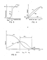
- FIG. 3 shows the temperature versus resistance characteristic of one embodiment of PTC resistive heater 14.
- PTC resistive heater 14 is at ambient temperature, typically a rather low temperature. Resistance will be at Rmi,,, shown at 34.
- Rmi resistance
- the temperature of PTC resistive heater 14 rapidly rises.
- T a anomaly (or Curie) temperature
- PTC resistive heater 14 is self- regulating at this point with respect to temperature.
- PTC resistive heater 14 in response to an increased rate of heat dissipation at the external surface of sensor 20, cooling PTC resistive heater 14 below T a , PTC resistive heater 14 will decrease its resistance approaching R mln' causing an increase in current in the circuit, resulting in an increase in power according to the known relationship of power, voltage and current. Conversely, in response to a temperature rise due to a decreased rate of heat dissipation at the external surface of sensor 20, which increases temperature above T a , PTC resistive heater 14 will increase its resistance toward its maximum value, Rmax, shown at 40. This will reduce circuit current and consequently reduce PTC resistive heater 14 power. Both of the foregoing responses drive PTC resistive heater 14 back toward stabilization at T a .
- PTC resistive heater 14 and conventional resistive heater 16 are electrically connected in series. In such series circuit, the current will be constant throughout, and voltage will be divided among the various components proportional to the resistance of each individual component. Accordingly, as the variation of resistance in PTC resistive heater 14 functions to vary the current to itself, it also simultaneously varies current to conventional resistive heater 16. Circuit power is directly related to circuit resistance. The result is that PTC resistive heater 14, by controlling its own power through its variation in resistance responsive to temperature, controls power in conventional resistive heater 16 responsive to such temperatures as well.
- Figure 3 shows that PTC resistive heater 14 resistance is a function of its temperature, which in turn is a function of rate of heat dissipation therefrom.
- Figure 4 further illustrates the above principle. It shows the relationship of individual heater power and the rate of heat dissipation at the external surface of sensor 20.
- Curve 42 represents conventional resistive heater 16 and curve 44 re- presentsPTC resistive heater 14.
- Points 46 and 48 represent power at the minimum rate of heat dissipation, as when the air vehicle is at rest on the ground, for conventional resistive heater 16 and PTC resistive heater 14 respectively. Under this condition, neither heater is operating at very high power.
- the temperature of PTC resistive heater 14 is at T a , as indicated at 38 in Figure 3.
- the temperature of the conventional resistive heater 16 is lowerthan that of PTC resistive heater 14 since the resistance of conventional resistive heater 16 is less than that of PTC resistive heater 14 when PTC resistive heater 14 is operating at T a .
- This relatively low temperature corresponding to the power at point 46, illustrates why inclusion of second conventional resistor heater 18, shown in Figure 1, may be desired.
- air data sensor 20 operates under all conditions at a temperature sufficient to ensure-that water droplets do not form in or on probe 22. This may occur during ground operations of air vehicles. Droplets that form in probe 22 are capable of closing off air passages, resulting in erroneous air data parameter calculations.
- the anomaly temperature is sufficient to preclude the formation of droplets in the portion of sensor 20 heated by PTC resistive heater 14.
- the probe tip where icing is critical, is heated by conventional resistive heater 16.
- the lower temperature of this heater may not be sufficient to preclude icing. This points to the use of second conventional resistive heater 18.
- second conventional resistive heater 18 When connected directly to a power source, second conventional resistive heater 18 operates at its maximum rated power as indicated by curve 51 in Figure 4 and is unaffected by variations in the resistance of the PTC resistive heater 14.
- second conventional resistive heater 18 When connected in parallel with the PTC resistive heater 14 as shown in Figure 1, second conventional resistive heater 18 operates at maximum rated power when the rate of heat dissipation from the external surface is at a minimum. Its power gradually decreases as the resistance of PTC resistive heater 14 decreases in response to an increasing rate of heat dissipation.
- Total power to probe 22, then, is a summation of the power to the two heaters in probe 22 which is equal to a summation of curve 42 and curve 51 at any given rate of heat dissipation.
- the maximum rated power of second conventional resistive heater 18 is selected to ensure that during conditions of minimum rate of heat dissipation, the power that it supplies, shown at point 53, in addition to the power from the conventional resistor heater 16, 'shown at point 46, results in a temperature in probe 22 that is sufficient to perform the anti-icing function by preventing formation of water droplets therein without heating probe 22 to temperatures that could result in damage to the heaters or in deterioration of probe 22.
- the range of resistance values for second conventional resistive heater 18 preferably is 200 to 300 ohms.
- Total heater power to sensor 20 is a summation of the power dissipated in PTC resistive heater 14, conventional resistive heater 16 and second conventional resistive heater 18.
- the summation of curves 42, 44 and 51 for any given rate of heat dissipation provides this value.
- point 50 represents the coincident terminuses of curves 42 and 44. Value of total power under conditions of maximum rate of heat dissipation is then equal to twice the power at point 50 plus the power indicated by curve 51.
- Figure 5 deals with the relationship of the power from PTC resistive heater 14 and conventional resistive heater 16 as a function of the ratio of their resistances.
- Second conventional resistive heater 18 is not considered in the figure.
- Curve 52 represents conventional resistive heater 16
- curve 54 represents PTC resistive heater 14.
- Point 58 where the ratio is one, is known as the crossover point and corresponds to point 50 in Figure 4. At this point the dominant heater with respect to the amount of power supplied switches from one to the other.
- Conventional resistive heater 16 dominates operation to the left of crossover point 58
- the PTC resistive heater 14 dominates operation to the right of the crossover point 58.
- PTC characteristic functions to continuously control total heater power in response to rate of heat dissipation from the PTC resistive heater.
- points 60 and 62 indicate heater operation at the minimum rate of heat dissipation and, accordingly, correspond to points 46 and 48 respectively in Figure 4.
- passive heater power control that is continuously variable as a function of rate of heat dissipation from the external surface of the sensor. It differs from previous uses of PTC material in that it utilizes the PTC characteristic to vary the cooperative heating of the conventional resistance heating means and the PTC heating means in an analog fashion to provide continuous variable control rather than using the PTC characteristic essentially as a digital switch.
Landscapes
- Engineering & Computer Science (AREA)
- Aviation & Aerospace Engineering (AREA)
- Physics & Mathematics (AREA)
- General Physics & Mathematics (AREA)
- Resistance Heating (AREA)
Applications Claiming Priority (2)
| Application Number | Priority Date | Filing Date | Title |
|---|---|---|---|
| US06/252,289 US4458137A (en) | 1981-04-09 | 1981-04-09 | Electric heater arrangement for fluid flow stream sensors |
| US252289 | 1981-04-09 |
Publications (3)
| Publication Number | Publication Date |
|---|---|
| EP0076306A1 EP0076306A1 (en) | 1983-04-13 |
| EP0076306A4 EP0076306A4 (en) | 1983-08-09 |
| EP0076306B1 true EP0076306B1 (en) | 1986-03-19 |
Family
ID=22955395
Family Applications (1)
| Application Number | Title | Priority Date | Filing Date |
|---|---|---|---|
| EP82901393A Expired EP0076306B1 (en) | 1981-04-09 | 1982-04-06 | Passive temperature control arrangement for fluid flow stream sensor heater |
Country Status (8)
| Country | Link |
|---|---|
| US (1) | US4458137A (enExample) |
| EP (1) | EP0076306B1 (enExample) |
| JP (1) | JPS58500494A (enExample) |
| BR (1) | BR8207580A (enExample) |
| CA (1) | CA1182158A (enExample) |
| DE (1) | DE3269927D1 (enExample) |
| IL (1) | IL65601A (enExample) |
| WO (1) | WO1982003693A1 (enExample) |
Families Citing this family (45)
| Publication number | Priority date | Publication date | Assignee | Title |
|---|---|---|---|---|
| US4759189A (en) * | 1985-12-02 | 1988-07-26 | Design & Manufacturing Corporation | Self-limiting thermal fluid displacement actuator |
| FR2601913B1 (fr) * | 1986-07-24 | 1988-12-02 | Manzoni Bouchot Sa | Dispositif de chauffage pour sonde hygrometrique de commande d'essuie-glace pour vehicules. |
| IL84611A (en) * | 1987-11-26 | 1991-11-21 | Ardon Gador | Apparatus and method for protection against heat |
| US5043558A (en) * | 1990-09-26 | 1991-08-27 | Weed Instrument Company, Inc. | Deicing apparatus and method utilizing heat distributing means contained within surface channels |
| US5552576A (en) * | 1992-02-21 | 1996-09-03 | The Bf Goodrich Company | Modular drainmast for aircraft |
| US5337602A (en) * | 1992-08-24 | 1994-08-16 | Gibson Michael E | Pitot static tube having accessible heating element |
| US5653538A (en) * | 1995-06-07 | 1997-08-05 | Rosemount Aerospace Inc. | Total temperature probe |
| DE19640606C1 (de) * | 1996-10-01 | 1997-09-11 | Nord Micro Elektronik Feinmech | Meßeinrichtung zur Erfassung von Stau- und Statikdrücken bei einem Fluggerät |
| WO1998016837A1 (en) * | 1996-10-16 | 1998-04-23 | Rosemount Aerospace Inc. | Heated air data probe |
| US6070475A (en) * | 1997-10-15 | 2000-06-06 | Rosemont Aerospace Inc. | Air data probe with heater means within wall |
| US6370450B1 (en) * | 1999-12-10 | 2002-04-09 | Rosemount Aerospace Inc. | Integrated total temperature probe system |
| US6414282B1 (en) | 2000-11-01 | 2002-07-02 | Rosemount Aerospace Inc. | Active heater control circuit and method used for aerospace probes |
| US6452542B1 (en) | 2001-03-02 | 2002-09-17 | Rosemount Aerospace Inc. | Integrated flight management system |
| DE10124530B8 (de) * | 2001-05-19 | 2006-01-12 | Eads Deutschland Gmbh | Sensorstruktur zur Strömungsdatenmessung an einem Strömungskörper |
| US6609825B2 (en) * | 2001-09-21 | 2003-08-26 | Rosemount Aerospace Inc. | Total air temperature probe providing improved anti-icing performance and reduced deicing heater error |
| US6892584B2 (en) * | 2002-11-19 | 2005-05-17 | Rosemount Aerospace Inc. | Fabricated pitot probe assembly |
| US6881932B2 (en) | 2003-04-29 | 2005-04-19 | Harco Laboratories, Inc. | High reliability heater modules |
| US6941805B2 (en) * | 2003-06-26 | 2005-09-13 | Rosemount Aerospace Inc. | Multi-function air data sensing probe having an angle of attack vane |
| FR2856880B1 (fr) * | 2003-06-27 | 2005-09-23 | Auxitrol Sa | Resistance chauffante notamment pour la chauffe d'une piece massive telle qu'une sonde de temperature et/ou de prise de pression |
| USD548634S1 (en) | 2005-09-20 | 2007-08-14 | Rosemount Aerospace Inc. | Total air temperature probe |
| US7357572B2 (en) * | 2005-09-20 | 2008-04-15 | Rosemount Aerospace Inc. | Total air temperature probe having improved deicing heater error performance |
| USD545227S1 (en) | 2005-09-20 | 2007-06-26 | Rosemount Aerospace Inc. | Total air temperature probe |
| DE102007016099A1 (de) * | 2007-03-27 | 2008-10-02 | Siemens Ag | Verfahren und Vorrichtung zum Reinigen eines auf elektromagnetischer Strahlung beruhenden Sensors |
| US7828477B2 (en) * | 2007-05-14 | 2010-11-09 | Rosemount Aerospace Inc. | Aspirated enhanced total air temperature probe |
| KR101721108B1 (ko) * | 2009-01-30 | 2017-03-29 | 엘지전자 주식회사 | 가변히터를 구비한 냉장고 |
| US8392141B2 (en) * | 2009-11-02 | 2013-03-05 | Rosemount Aerospace Inc. | Total air temperature probe and method for reducing de-icing/anti-icing heater error |
| US8764175B2 (en) * | 2012-07-27 | 2014-07-01 | Xerox Corporation | Heater configuration for a melting device with non-uniform thermal load |
| US9322685B2 (en) * | 2014-06-30 | 2016-04-26 | The Boeing Company | MEMS-based conformal air speed sensor |
| US10179654B2 (en) * | 2015-10-20 | 2019-01-15 | Honeywell International Inc. | Architecture for air data probe power supply control |
| US9791304B2 (en) * | 2015-10-21 | 2017-10-17 | Honeywell International Inc. | Air data probe heater utilizing low melting point metal |
| FR3047564B1 (fr) * | 2016-02-09 | 2018-01-19 | Aer | Sonde de mesure de vitesse anemometrique d'un aeronef |
| US9523594B1 (en) | 2016-02-23 | 2016-12-20 | Honeywell International Inc. | Power control for an air data probe |
| US10442539B2 (en) * | 2017-05-12 | 2019-10-15 | Bell Helicopter Textron Inc. | Anti-ice system for thermally fragile materials |
| US11181545B2 (en) | 2017-08-17 | 2021-11-23 | Rosemount Aerospace Inc. | Angle of attack sensor with thermal enhancement |
| US10730637B2 (en) | 2017-09-29 | 2020-08-04 | Rosemount Aerospace Inc. | Integral vane base angle of attack sensor |
| SE541696C2 (en) * | 2017-10-09 | 2019-11-26 | Mobile Climate Control Sverige Ab | Selfregulating heater |
| US11105691B2 (en) * | 2018-03-30 | 2021-08-31 | Honeywell International Inc. | Self-regulating heating system for a total air temperature probe |
| FR3084159B1 (fr) * | 2018-07-20 | 2021-09-24 | Safran Aircraft Engines | Dispositif de mesure avec un module de regulation thermique de sa temperature |
| US11235881B2 (en) | 2018-09-13 | 2022-02-01 | Goodrich Corporation | Hybrid heater for aircraft wing ice protection |
| CN109625290A (zh) * | 2018-12-05 | 2019-04-16 | 太原航空仪表有限公司 | 一种大气数据探头双通道防除冰装置 |
| US11162970B2 (en) | 2019-06-17 | 2021-11-02 | Rosemount Aerospace Inc. | Angle of attack sensor |
| US11459112B2 (en) * | 2019-07-19 | 2022-10-04 | Rosemount Aerospace Inc. | Active aircraft probe heat monitor and method of use |
| US11425797B2 (en) | 2019-10-29 | 2022-08-23 | Rosemount Aerospace Inc. | Air data probe including self-regulating thin film heater |
| US11649057B2 (en) | 2019-12-13 | 2023-05-16 | Rosemount Aerospace Inc. | Static plate heating arrangement |
| US11745879B2 (en) * | 2020-03-20 | 2023-09-05 | Rosemount Aerospace Inc. | Thin film heater configuration for air data probe |
Family Cites Families (27)
| Publication number | Priority date | Publication date | Assignee | Title |
|---|---|---|---|---|
| US1767249A (en) * | 1920-08-09 | 1930-06-24 | Remington Arms Co Inc | Electric heater |
| US1919068A (en) * | 1929-04-10 | 1933-07-18 | Gen Electric | Temperature regulator |
| GB490481A (en) * | 1937-08-06 | 1938-08-16 | Henry James Osborn | An improved electric heater |
| US2221547A (en) * | 1938-03-12 | 1940-11-12 | Square D Co | Heat protected pitot-static tube |
| US2300654A (en) * | 1940-12-12 | 1942-11-03 | Daiber Emil | Pitot tube |
| US3030807A (en) * | 1959-11-19 | 1962-04-24 | Aero Res Instr Co Inc | Heated pitot tube assembly |
| DE1155855B (de) * | 1962-09-27 | 1963-10-17 | Philips Nv | Vorrichtung zum Schutz eines elektrischen Geraetes |
| US3338476A (en) * | 1965-10-24 | 1967-08-29 | Texas Instruments Inc | Heating device for use with aerosol containers |
| JPS4318230Y1 (enExample) * | 1965-12-23 | 1968-07-27 | ||
| GB1175532A (en) * | 1966-07-06 | 1969-12-23 | Avimo Ltd | Improvements in or relating to Pressure Heads for Aircraft |
| GB1181216A (en) * | 1966-07-26 | 1970-02-11 | Rosemount Eng Co Ltd | Improvements in or relating to Aerodynamic Components Mounted Externally on an Aircraft |
| US3375774A (en) * | 1967-01-05 | 1968-04-02 | Matsushita Electric Industrial Co Ltd | Fully automatic electric coffee pot |
| US3476293A (en) * | 1967-08-29 | 1969-11-04 | Texas Instruments Inc | Aerosol heater with improved control means |
| DE2138495A1 (de) * | 1971-07-31 | 1973-02-01 | Dornier Ag | Heizeinrichtung fuer stroemungssonden |
| JPS498919A (enExample) * | 1972-05-24 | 1974-01-26 | ||
| JPS49122058A (enExample) * | 1973-03-29 | 1974-11-21 | ||
| US3835434A (en) * | 1973-06-04 | 1974-09-10 | Sprague Electric Co | Ptc resistor package |
| US3882721A (en) * | 1973-11-16 | 1975-05-13 | Rosemount Inc | Vane type airflow sensor |
| GB1502479A (en) * | 1974-11-20 | 1978-03-01 | Matsushita Electric Industrial Co Ltd | Sealed thermostatic electric resistance heaters |
| NL7603997A (nl) * | 1976-04-15 | 1977-10-18 | Philips Nv | Elektrische verhittingsinrichting omvattende een weerstandslichaam uit p.t.c.-materiaal. |
| US4121088A (en) * | 1976-10-18 | 1978-10-17 | Rosemount Inc. | Electrically heated air data sensing device |
| JPS53110133A (en) * | 1977-03-07 | 1978-09-26 | Tdk Electronics Co Ltd | Porcelain heating element made from positive characteristic semiconductor |
| US4246468A (en) * | 1978-01-30 | 1981-01-20 | Raychem Corporation | Electrical devices containing PTC elements |
| JPS5553993U (enExample) * | 1978-10-05 | 1980-04-11 | ||
| DE2919763C2 (de) * | 1979-05-16 | 1983-07-07 | Danfoss A/S, 6430 Nordborg | Zerstäubungsbrenner für Ölfeuerungsanlagen |
| US4246787A (en) * | 1979-06-13 | 1981-01-27 | Texas Instruments Incorporated | Fast response temperature sensor and method of making |
| JPS5757286Y2 (enExample) * | 1979-06-18 | 1982-12-09 |
-
1981
- 1981-04-09 US US06/252,289 patent/US4458137A/en not_active Expired - Lifetime
-
1982
- 1982-04-06 WO PCT/US1982/000423 patent/WO1982003693A1/en not_active Ceased
- 1982-04-06 BR BR8207580A patent/BR8207580A/pt not_active IP Right Cessation
- 1982-04-06 DE DE8282901393T patent/DE3269927D1/de not_active Expired
- 1982-04-06 EP EP82901393A patent/EP0076306B1/en not_active Expired
- 1982-04-06 JP JP57501471A patent/JPS58500494A/ja active Granted
- 1982-04-08 CA CA000400807A patent/CA1182158A/en not_active Expired
- 1982-04-25 IL IL65601A patent/IL65601A/xx not_active IP Right Cessation
Also Published As
| Publication number | Publication date |
|---|---|
| WO1982003693A1 (en) | 1982-10-28 |
| EP0076306A1 (en) | 1983-04-13 |
| EP0076306A4 (en) | 1983-08-09 |
| CA1182158A (en) | 1985-02-05 |
| US4458137A (en) | 1984-07-03 |
| DE3269927D1 (en) | 1986-04-24 |
| JPH0378757B2 (enExample) | 1991-12-16 |
| BR8207580A (pt) | 1983-03-29 |
| IL65601A (en) | 1987-10-30 |
| JPS58500494A (ja) | 1983-03-31 |
Similar Documents
| Publication | Publication Date | Title |
|---|---|---|
| EP0076306B1 (en) | Passive temperature control arrangement for fluid flow stream sensor heater | |
| US6211494B1 (en) | Drainmast with integral electronic temperature control | |
| EP2004488B1 (en) | Ice protection system | |
| US4246468A (en) | Electrical devices containing PTC elements | |
| US4316080A (en) | Temperature control devices | |
| US6753513B2 (en) | Propeller de-icing system | |
| US4072848A (en) | Electrical heating cable with temperature self-limiting heating elements | |
| US4821010A (en) | Thermal cutoff heater | |
| EP1204012B1 (en) | Active heater control circuit and method used for aerospace probes | |
| US3757808A (en) | Electronic mass airflow sensing and control system | |
| US11425797B2 (en) | Air data probe including self-regulating thin film heater | |
| EP0228808B1 (en) | A temperature sensitive device | |
| GB2038550A (en) | Circuit protection devices comprising ptc elements | |
| US20180063886A1 (en) | Ptc heater with autonomous control | |
| CA1301284C (en) | Hot melt adhesive applicator and temperature control circuit therefor | |
| EP0352987A3 (en) | Solid state circuit protector | |
| US5465618A (en) | Thermal flow sensor and heat-sensitive resistor therefor | |
| US4396892A (en) | Accelerated warm-up crystal oven | |
| EP3883337A1 (en) | Thin film heater configuration for air data probe | |
| EP0219984B1 (en) | Flow sensing device | |
| GB2047487A (en) | Heating circuits | |
| WO2002026559A1 (en) | Drainmast with integral electronic temperature control | |
| US5380989A (en) | Inductive heating element with magnetic and thermistor materials | |
| ES481662A1 (es) | Perfeccionamientos en interruptores de proteccion por co- rriente de defecto. | |
| EP4445237B1 (en) | Temperature monitoring system |
Legal Events
| Date | Code | Title | Description |
|---|---|---|---|
| PUAI | Public reference made under article 153(3) epc to a published international application that has entered the european phase |
Free format text: ORIGINAL CODE: 0009012 |
|
| 17P | Request for examination filed |
Effective date: 19821201 |
|
| AK | Designated contracting states |
Designated state(s): DE FR GB SE |
|
| GRAA | (expected) grant |
Free format text: ORIGINAL CODE: 0009210 |
|
| AK | Designated contracting states |
Kind code of ref document: B1 Designated state(s): DE FR GB SE |
|
| REF | Corresponds to: |
Ref document number: 3269927 Country of ref document: DE Date of ref document: 19860424 |
|
| ET | Fr: translation filed | ||
| PLBE | No opposition filed within time limit |
Free format text: ORIGINAL CODE: 0009261 |
|
| STAA | Information on the status of an ep patent application or granted ep patent |
Free format text: STATUS: NO OPPOSITION FILED WITHIN TIME LIMIT |
|
| 26N | No opposition filed | ||
| EAL | Se: european patent in force in sweden |
Ref document number: 82901393.7 |
|
| PGFP | Annual fee paid to national office [announced via postgrant information from national office to epo] |
Ref country code: SE Payment date: 19960401 Year of fee payment: 15 |
|
| PG25 | Lapsed in a contracting state [announced via postgrant information from national office to epo] |
Ref country code: SE Effective date: 19970407 |
|
| EUG | Se: european patent has lapsed |
Ref document number: 82901393.7 |
|
| PGFP | Annual fee paid to national office [announced via postgrant information from national office to epo] |
Ref country code: DE Payment date: 20000320 Year of fee payment: 19 |
|
| PGFP | Annual fee paid to national office [announced via postgrant information from national office to epo] |
Ref country code: FR Payment date: 20010319 Year of fee payment: 20 |
|
| PGFP | Annual fee paid to national office [announced via postgrant information from national office to epo] |
Ref country code: GB Payment date: 20010321 Year of fee payment: 20 |
|
| PG25 | Lapsed in a contracting state [announced via postgrant information from national office to epo] |
Ref country code: DE Free format text: LAPSE BECAUSE OF NON-PAYMENT OF DUE FEES Effective date: 20010430 |
|
| REG | Reference to a national code |
Ref country code: GB Ref legal event code: IF02 |
|
| PG25 | Lapsed in a contracting state [announced via postgrant information from national office to epo] |
Ref country code: GB Free format text: LAPSE BECAUSE OF EXPIRATION OF PROTECTION Effective date: 20020405 |
|
| REG | Reference to a national code |
Ref country code: GB Ref legal event code: PE20 Effective date: 20020405 |