EP0076205B1 - Cassette magnétique à courroie élastique de tension - Google Patents
Cassette magnétique à courroie élastique de tension Download PDFInfo
- Publication number
- EP0076205B1 EP0076205B1 EP82401724A EP82401724A EP0076205B1 EP 0076205 B1 EP0076205 B1 EP 0076205B1 EP 82401724 A EP82401724 A EP 82401724A EP 82401724 A EP82401724 A EP 82401724A EP 0076205 B1 EP0076205 B1 EP 0076205B1
- Authority
- EP
- European Patent Office
- Prior art keywords
- roller
- slide
- cassette
- bulged
- magnetic tape
- Prior art date
- Legal status (The legal status is an assumption and is not a legal conclusion. Google has not performed a legal analysis and makes no representation as to the accuracy of the status listed.)
- Expired
Links
- 238000011144 upstream manufacturing Methods 0.000 claims description 3
- 238000004804 winding Methods 0.000 claims description 3
- 239000000725 suspension Substances 0.000 claims 1
- 230000010355 oscillation Effects 0.000 description 2
- 238000005094 computer simulation Methods 0.000 description 1
- 230000007547 defect Effects 0.000 description 1
- 230000000694 effects Effects 0.000 description 1
- 238000000034 method Methods 0.000 description 1
- 230000000717 retained effect Effects 0.000 description 1
- 230000000087 stabilizing effect Effects 0.000 description 1
Images
Classifications
-
- G—PHYSICS
- G11—INFORMATION STORAGE
- G11B—INFORMATION STORAGE BASED ON RELATIVE MOVEMENT BETWEEN RECORD CARRIER AND TRANSDUCER
- G11B23/00—Record carriers not specific to the method of recording or reproducing; Accessories, e.g. containers, specially adapted for co-operation with the recording or reproducing apparatus ; Intermediate mediums; Apparatus or processes specially adapted for their manufacture
- G11B23/02—Containers; Storing means both adapted to cooperate with the recording or reproducing means
- G11B23/04—Magazines; Cassettes for webs or filaments
- G11B23/08—Magazines; Cassettes for webs or filaments for housing webs or filaments having two distinct ends
- G11B23/087—Magazines; Cassettes for webs or filaments for housing webs or filaments having two distinct ends using two different reels or cores
- G11B23/08707—Details
- G11B23/08778—Driving features, e.g. belt
Definitions
- the present invention relates to a cassette for magnetic tape, of the type comprising two reels for winding a magnetic tape, means for directing the magnetic tape in front of a recording-reading device, means for driving the magnetic tape, a tension adjustment device comprising a cylindrical sliding roller kept pressed against the two coils by means of an endless elastic belt stretched between the sliding roller and at least one deflection roller by enveloping a part of the peripheries facing the coils, the magnetic strip winding and unwinding tangentially on each reel, respectively upstream and downstream of the pressure lines of the sliding roller on the two reels.
- a cassette of this type is known from United States Patent No. 3,907,230, in the name of the Applicant. We can refer to this document to understand exactly the function of the belt, which, by a complex differential elongation effect ensures a web tension.
- the tension belt drifts vertically on the sliding roller, without anything can't stop it.
- the object of the invention is to overcome this drawback and therefore to provide a cassette having great stability in height of the belt in reciprocating use.
- the stabilizing action of the convex roller is known per se, for example from US-A-4146 194, but the invention has the merit of showing that it is possible to place a convex roller satisfying these requirements despite the complex trajectory (and in any case non-circulating) of the sliding roller.
- the support is a plate capable of sliding on the bottom of the cassette, carrying the axes of the sliding and convex rollers, and provided with a guide notch in which is engaged a stud projecting from the bottom of the cassette, in order to fix the position of the support as a function of the position of the sliding roller.
- the plate is held on the bottom of the cassette by means of an elastic support device.
- Such a support plate provides an ingenious and simple execution solution to the problem of the substantially integral transfer of the tension exerted by the belt on the convex roller to the sliding roller, in all the positions of the sliding roller.
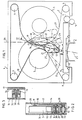
- FIG. 1 shows a cassette 1, the magnetic tape 2 of which is unwound from a reel 3 onto a reel 4, or vice versa, by means of a drive roller 5, belonging to the recording - reading device in which the cassette is inserted.
- Means 8 associated with rollers 9 allow the magnetic tape 2 to be guided in front of the reading-recording device 5, 6.
- the belt tension adjustment device comprises an elastic belt 10 passing over two idler rollers 11, partially enveloping the coils 3 and 4, and passing over a convex roller 12 associated with a cylindrical sliding roller 13 kept pressed against the reels 3 and 4 by the elastic tension of the belt 11 exerted on the convex roller 12 and transmitted to the roller 13 via the common support 14 of the axes 15 and 16 of the convex rollers 12 and sliding gear 13.
- the support 14 consists of an elongated plate sliding with the minimum of friction on the bottom 17 of the cassette 1.
- the position of the plate 14 is determined, on the one hand, by the position of the sliding roller 13 (this latter position being a function of the unwinding of the strip), and, on the other hand, by a device fixing the trajectory of the convex roller 12: it is, in this case, a rectilinear guide notch 18 provided at one end of the entry plate on the plane II-II passing through the axes 15-16 of the convex rollers 12 and sliding device 13, and situated, with respect to the sliding roller 13, on the side opposite to the convex roller 12.
- a stud 19 with head 20 fixed to the bottom 17 of the cassette, in the median plane of trace 26, guides the notch 18 during the movement of the sliding roller 13.
- Two other positions 14 ′ and 14 ′′ of the plate 14 are shown in dotted lines in FIG. 1.
- This trajectory fixing device 18-19 makes it possible, on the one hand, to respect the proper trajectory of the sliding roller 13 (non-circular trajectory), and not to influence the overall value of the pressure exerted by the roller 13 on the coils 3 and 4, assuming that the friction of the plate 14 on the bottom 17, and that the forces developed at the point of contact of the stud 19 on the walls of the notch 18 are negligible with regard to said pressure (which is practically verified for a notch 18 centered on the plane II-II).
- the device 18-19 fixes the position of the convex roller 12, for each position of the sliding roller 13, and, consequently, fixes the distribution and the orientation of the forces of pressure transmitted respectively to each coil 3 and 4, by said sliding roller 13.
- the curved roller 12 is located in the zone of the cassette included in the variable dihedral angle formed by the intersection of the planes of traces 23 and 24, respective common tangent planes of the sliding roller 13 and the coils 3 and 4 (again neglecting the thickness of the belt 10).
- the convex roller 12 (here a biconical roller) has an average diameter substantially half the diameter of the sliding roller 13, and has been mounted, on the wafer 14, in the immediate vicinity of the pressure roller, the average length of the arm between the axis 16 of the sliding roller and the stud 19 reaching practically three times the distance between the axes separating the two rollers 12 and 13. It should however be understood that these proportions, in no way critical, are given only by way of example and do not should not be considered limiting.
- the dimensions of the sliding roller 13 are limited on the one hand by the fact that the roller must not be able to pass between the two coils, and, on the other hand, by the fact that the magnetic strip 2 must be wind and unwind tangentially on each coil (at 27) respectively upstream and downstream of the pressure lines (or contact 22, 21) of the sliding roller 13 on the two coils.
- the rollers 12 and 13 are mounted in a known manner by means of bearings 28 on their respective axes 15 and 16. It will be noted that one of the axes, the axis 16 of the sliding roller, is hollow and houses a spring 29 pushing a ball 30 against the upper face 31 of the cassette, which ensures the stability in height of the plate 14, therefore of the biconical roller 15, and, consequently, of the belt 10.
- FIG. 3 represents a method of mounting the sliding roller 13, according to which the roller is mounted in a known manner using a single radial ball bearing 32 which leaves the roller 13 a slight freedom of oscillation.
- This faculty of oscillation allows the roller 13 to better withstand a minimal defect in the respective positioning of the coils 3, 4, while maintaining with them a practically normal contact line.
- This oscillating assembly does not introduce any drift in height of the belt 10 which continues to be stabilized by the domed roller 12.
Landscapes
- Registering, Tensioning, Guiding Webs, And Rollers Therefor (AREA)
- Manufacturing Of Magnetic Record Carriers (AREA)
- Advancing Webs (AREA)
- Automatic Tape Cassette Changers (AREA)
Applications Claiming Priority (2)
| Application Number | Priority Date | Filing Date | Title |
|---|---|---|---|
| FR8118488 | 1981-09-30 | ||
| FR8118488A FR2513791A1 (fr) | 1981-09-30 | 1981-09-30 | Cassette magnetique a courroie elastique de tension |
Publications (2)
| Publication Number | Publication Date |
|---|---|
| EP0076205A1 EP0076205A1 (fr) | 1983-04-06 |
| EP0076205B1 true EP0076205B1 (fr) | 1985-12-11 |
Family
ID=9262638
Family Applications (1)
| Application Number | Title | Priority Date | Filing Date |
|---|---|---|---|
| EP82401724A Expired EP0076205B1 (fr) | 1981-09-30 | 1982-09-23 | Cassette magnétique à courroie élastique de tension |
Country Status (6)
| Country | Link |
|---|---|
| US (1) | US4571655A (OSRAM) |
| EP (1) | EP0076205B1 (OSRAM) |
| JP (1) | JPS5870466A (OSRAM) |
| CA (1) | CA1193720A (OSRAM) |
| DE (1) | DE3267934D1 (OSRAM) |
| FR (1) | FR2513791A1 (OSRAM) |
Families Citing this family (3)
| Publication number | Priority date | Publication date | Assignee | Title |
|---|---|---|---|---|
| NL9500244A (nl) * | 1994-02-17 | 1995-10-02 | Matsushita Electric Ind Co Ltd | Bandcassette. |
| EP0760153A1 (en) * | 1994-05-19 | 1997-03-05 | Imation Corp. | Tape guides for data cartridges |
| US5573195A (en) * | 1995-02-24 | 1996-11-12 | Minnesota Mining & Manufacturing Company | Data cartridge with pivoting roller yoke |
Family Cites Families (18)
| Publication number | Priority date | Publication date | Assignee | Title |
|---|---|---|---|---|
| US601110A (en) * | 1898-03-22 | Rope drive mechanism | ||
| DE1118485B (de) * | 1957-03-25 | 1961-11-30 | Telefunken Patent | Laufwerk fuer Geraete zur Schallaufzeichnung und/oder -wiedergabe, z.B. fuer Magnettongeraete |
| GB860272A (en) * | 1957-11-01 | 1961-02-01 | Nat Res Dev | Improvements in or relating to drive mechanism for film or other flexible material |
| FR1427665A (fr) * | 1964-07-24 | 1966-02-11 | Thomson Houston Comp Francaise | Perfectionnements aux dispositifs de déroulement |
| US3342632A (en) * | 1964-08-05 | 1967-09-19 | Ibm | Magnetic coating |
| JPS4913889Y1 (OSRAM) * | 1969-04-18 | 1974-04-05 | ||
| US3802644A (en) * | 1971-10-01 | 1974-04-09 | Motorola Inc | Differential belt web transport |
| CH575636A5 (OSRAM) * | 1972-08-21 | 1976-05-14 | Schlumberger Inst System | |
| US3974982A (en) * | 1975-02-24 | 1976-08-17 | Raymond Engineering Inc. | Tape transport |
| SU584334A1 (ru) * | 1975-08-22 | 1977-12-15 | Предприятие П/Я А-3759 | Кассета |
| US4159811A (en) * | 1976-11-22 | 1979-07-03 | Grant Frederic F | Tape transport cartridge |
| US4102516A (en) * | 1977-04-14 | 1978-07-25 | Information Terminals Corporation | Tensioning means for belt driven tape cassette |
| US4162774A (en) * | 1977-10-17 | 1979-07-31 | Verbatim Corporation | Belt drive cartridge |
| US4146194A (en) * | 1977-11-10 | 1979-03-27 | Information Terminals Corp | Floating roller tape cartridge |
| US4219169A (en) * | 1977-11-10 | 1980-08-26 | Verbatim Corporation | Floating roller magnetic tape cartridge |
| JPS5597046A (en) * | 1979-01-17 | 1980-07-23 | Toshiba Corp | Tape running device |
| US4205808A (en) * | 1979-01-22 | 1980-06-03 | Verbatim Corporation | Tape cartridge |
| US4335857A (en) * | 1980-06-24 | 1982-06-22 | Newell Research Corporation | Web aligning system |
-
1981
- 1981-09-30 FR FR8118488A patent/FR2513791A1/fr active Granted
-
1982
- 1982-09-17 US US06/419,356 patent/US4571655A/en not_active Expired - Fee Related
- 1982-09-23 EP EP82401724A patent/EP0076205B1/fr not_active Expired
- 1982-09-23 DE DE8282401724T patent/DE3267934D1/de not_active Expired
- 1982-09-29 CA CA000412458A patent/CA1193720A/en not_active Expired
- 1982-09-30 JP JP57169920A patent/JPS5870466A/ja active Pending
Also Published As
| Publication number | Publication date |
|---|---|
| FR2513791A1 (fr) | 1983-04-01 |
| EP0076205A1 (fr) | 1983-04-06 |
| US4571655A (en) | 1986-02-18 |
| FR2513791B1 (OSRAM) | 1984-04-20 |
| CA1193720A (en) | 1985-09-17 |
| JPS5870466A (ja) | 1983-04-26 |
| DE3267934D1 (en) | 1986-01-23 |
Similar Documents
| Publication | Publication Date | Title |
|---|---|---|
| CH638155A5 (fr) | Appareil de distribution de feuilles. | |
| FR2522430A1 (fr) | Dispositif de lecture et/ou d'ecriture magnetique | |
| EP0076205B1 (fr) | Cassette magnétique à courroie élastique de tension | |
| US4957234A (en) | Cutting device for rolls of adhesive tape | |
| FR2582134A3 (fr) | Cassette de bande magnetique et dispositif d'envidage pouvant etre utilise en combinaison avec une telle cassette | |
| FR2566161A3 (fr) | Cassette de bande comportant au moins un ressort presseur, et ressort presseur pour celle-ci | |
| FR2586616A1 (fr) | Cartouche de ruban d'impression pour machine imprimante, notamment pour impression par transfert thermique | |
| EP0104989B1 (fr) | Instrument pour l'application de rubans adhésifs | |
| FR2497127A1 (fr) | Appareil et procede pour decouper des fentes dans des rubans d'ailette d'echangeur de chaleur | |
| FR2545254A1 (fr) | Appareil a bande magnetique | |
| FR2664731A1 (fr) | Dispositif de maintien en position d'elements rotatifs de cassette contenant un ruban. | |
| FR2546653A1 (fr) | Cassette a bande magnetique comportant un element de nettoyage pour le nettoyage du cabestan d'un appareil a bande magnetique | |
| FR2519789A1 (fr) | Mecanisme d'entrainement des cabestans dans les enregistreurs a bande | |
| FR2604392A1 (fr) | Devidoir de ruban correcteur du type a enlevement | |
| FR2697820A1 (fr) | Organe de guidage et de régulation de la tension d'une bande de papier. | |
| JPS6349920Y2 (OSRAM) | ||
| FR1464352A (fr) | Dispositif de commande pour l'avancement de bandes d'enregistrement | |
| FR2705159A1 (fr) | Appareil à bande magnétique et unité de tête magnétique destinés à être utilisés dans l'appareil à bande magnétique. | |
| CH276170A (fr) | Dispositif d'entraînement pour le déplacement intermittent d'un ruban mince le long d'une fenêtre d'image. | |
| FR2848803A1 (fr) | Dispositif de controle de la rotation du tambour d'un appareil distributeur de materiau d'essuyage | |
| CH378677A (fr) | Dispositif de lecture pour film sonore à piste magnétique | |
| FR2529817A1 (fr) | Dispositif pour decouper transversalement des laies de films en defilement | |
| BE732826A (OSRAM) | ||
| EP3330059A1 (fr) | Distributeur d'adhesif et dispositif de raccordement de gaines comportant un tel distributeur | |
| EP1216908A1 (fr) | Dispositif de sécurité pour le maintien latéral du câble d' une installation de transport à câble |
Legal Events
| Date | Code | Title | Description |
|---|---|---|---|
| PUAI | Public reference made under article 153(3) epc to a published international application that has entered the european phase |
Free format text: ORIGINAL CODE: 0009012 |
|
| AK | Designated contracting states |
Designated state(s): CH DE GB IT LI NL SE |
|
| 17P | Request for examination filed |
Effective date: 19830218 |
|
| ITF | It: translation for a ep patent filed | ||
| GRAA | (expected) grant |
Free format text: ORIGINAL CODE: 0009210 |
|
| AK | Designated contracting states |
Designated state(s): CH DE GB IT LI NL SE |
|
| REF | Corresponds to: |
Ref document number: 3267934 Country of ref document: DE Date of ref document: 19860123 |
|
| PLBE | No opposition filed within time limit |
Free format text: ORIGINAL CODE: 0009261 |
|
| STAA | Information on the status of an ep patent application or granted ep patent |
Free format text: STATUS: NO OPPOSITION FILED WITHIN TIME LIMIT |
|
| 26N | No opposition filed | ||
| PGFP | Annual fee paid to national office [announced via postgrant information from national office to epo] |
Ref country code: CH Payment date: 19910718 Year of fee payment: 10 |
|
| PGFP | Annual fee paid to national office [announced via postgrant information from national office to epo] |
Ref country code: GB Payment date: 19910808 Year of fee payment: 10 |
|
| PGFP | Annual fee paid to national office [announced via postgrant information from national office to epo] |
Ref country code: SE Payment date: 19910815 Year of fee payment: 10 |
|
| ITTA | It: last paid annual fee | ||
| PGFP | Annual fee paid to national office [announced via postgrant information from national office to epo] |
Ref country code: NL Payment date: 19910930 Year of fee payment: 10 |
|
| PGFP | Annual fee paid to national office [announced via postgrant information from national office to epo] |
Ref country code: DE Payment date: 19911001 Year of fee payment: 10 |
|
| PG25 | Lapsed in a contracting state [announced via postgrant information from national office to epo] |
Ref country code: GB Effective date: 19920923 |
|
| PG25 | Lapsed in a contracting state [announced via postgrant information from national office to epo] |
Ref country code: SE Effective date: 19920924 |
|
| PG25 | Lapsed in a contracting state [announced via postgrant information from national office to epo] |
Ref country code: LI Effective date: 19920930 Ref country code: CH Effective date: 19920930 |
|
| PG25 | Lapsed in a contracting state [announced via postgrant information from national office to epo] |
Ref country code: NL Effective date: 19930401 |
|
| NLV4 | Nl: lapsed or anulled due to non-payment of the annual fee | ||
| GBPC | Gb: european patent ceased through non-payment of renewal fee |
Effective date: 19920923 |
|
| REG | Reference to a national code |
Ref country code: CH Ref legal event code: PL |
|
| PG25 | Lapsed in a contracting state [announced via postgrant information from national office to epo] |
Ref country code: DE Effective date: 19930602 |
|
| EUG | Se: european patent has lapsed |
Ref document number: 82401724.8 Effective date: 19930406 |