EP0076194B1 - Système d'équilibrage d'un couple de balourd, utilisation d'un tel système pour une antenne de radar aéroporté, et antenne équilibrée par un tel système - Google Patents
Système d'équilibrage d'un couple de balourd, utilisation d'un tel système pour une antenne de radar aéroporté, et antenne équilibrée par un tel système Download PDFInfo
- Publication number
- EP0076194B1 EP0076194B1 EP82401686A EP82401686A EP0076194B1 EP 0076194 B1 EP0076194 B1 EP 0076194B1 EP 82401686 A EP82401686 A EP 82401686A EP 82401686 A EP82401686 A EP 82401686A EP 0076194 B1 EP0076194 B1 EP 0076194B1
- Authority
- EP
- European Patent Office
- Prior art keywords
- balancing
- antenna
- cable
- rotary axis
- center
- Prior art date
- Legal status (The legal status is an assumption and is not a legal conclusion. Google has not performed a legal analysis and makes no representation as to the accuracy of the status listed.)
- Expired
Links
Images


Classifications
-
- F—MECHANICAL ENGINEERING; LIGHTING; HEATING; WEAPONS; BLASTING
- F16—ENGINEERING ELEMENTS AND UNITS; GENERAL MEASURES FOR PRODUCING AND MAINTAINING EFFECTIVE FUNCTIONING OF MACHINES OR INSTALLATIONS; THERMAL INSULATION IN GENERAL
- F16F—SPRINGS; SHOCK-ABSORBERS; MEANS FOR DAMPING VIBRATION
- F16F15/00—Suppression of vibrations in systems; Means or arrangements for avoiding or reducing out-of-balance forces, e.g. due to motion
- F16F15/28—Counterweights, i.e. additional weights counterbalancing inertia forces induced by the reciprocating movement of masses in the system, e.g. of pistons attached to an engine crankshaft; Attaching or mounting same
-
- H—ELECTRICITY
- H01—ELECTRIC ELEMENTS
- H01Q—ANTENNAS, i.e. RADIO AERIALS
- H01Q3/00—Arrangements for changing or varying the orientation or the shape of the directional pattern of the waves radiated from an antenna or antenna system
- H01Q3/02—Arrangements for changing or varying the orientation or the shape of the directional pattern of the waves radiated from an antenna or antenna system using mechanical movement of antenna or antenna system as a whole
- H01Q3/08—Arrangements for changing or varying the orientation or the shape of the directional pattern of the waves radiated from an antenna or antenna system using mechanical movement of antenna or antenna system as a whole for varying two co-ordinates of the orientation
Definitions
- the present invention relates to a system for balancing an unbalance torque, its use for balancing an airborne radar antenna and an antenna balanced by such a system.
- the axis carrying the antenna must accommodate elements such as motors, angle copying elements or rotating joints.
- the antenna is therefore placed in complete overhang with respect to this axis.
- the overhang is often very large and can reach fifteen centimeters for large antennas.
- the carrier aircraft can impose load factors of up to 10 g on the antenna.
- the mass of the antenna and therefore the unbalance torque when it is not balanced, are multiplied by this factor.
- the unbalance can then exceed the maximum possible engine torque.
- the balancing of a part in rotation around an axis is carried out by masses carried by the device for attaching the movable part opposite said part with respect to the axis of rotation considered.
- the balancing weights can be a nuisance, either by their very mass which is added to the mass of the rotating mechanism, or by their volume which limits the extent of the rotational movement.
- the transmission means consist of rigid links which rigidly link the balancing mass to the attachment part of the element to be balanced, which has drawbacks in terms vibration resistance and mechanical strength.
- the system for balancing an unbalance torque for an element which is cantilevered relative to a fixed axis of rotation around which it can pivot comprising a balancing mass placed at a distance from the part of attachment of this element to its axis of rotation and of means for transmitting the rotational movements of the cantilever element to the balancing mass, is characterized in that these transmission means are flexible connections which impose at the center of gravity of the balancing mass a rotational movement around a fixed axis of rotation and parallel to the axis of rotation of the cantilever element and following an angular displacement opposite to that of the center of gravity of the cantilever element.
- references designate elements that are identical or play the same role.
- the attachment piece 4 is integral with the antenna 1.
- the antenna assembly 1, 2, 3, 4 and the orientation mechanism itself does not constitute the subject of the invention. will not be described in detail.
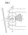
- the appended figures 1, 2, 3 are side views in section along a vertical plane P passing through the center of rotation O.
- the three axes of rotation are designated by x'Ox, transverse horizontal axis represented only by its trace O on the plane P, y'Oy, vertical axis, and z'Oz, longitudinal horizontal axis.
- the antenna 1 pivots around the first axis x'Ox with an angle ⁇ 0 relative to the plane (x'Ox, z'Oz), around the second axis y'Oy with an angle ⁇ a relative to the plane (x ' Ox, y'Oy) and around the third axis of rotation z'Oz with an angle ⁇ ⁇ relative to the plane (y'Oy, z'Oz).
- Figure 1 shows the side view of a balancing system according to the prior art.
- the balancing of the antenna unbalance is carried out at using a mass 5 fixed to the attachment piece 4 on the other side of the antenna relative to the center of rotation 0.
- the mass acts directly on the axis of rotation x'Ox and its volume limit the antenna travel at 0 and ⁇ .
- FIG. 2 represents the vertical section of a preferred embodiment of the balancing system according to the invention.
- the attachment piece 4 is integral with the same axis of rotation x'Ox as a vertical pulley 6.
- the assembly formed by the antenna 1 and the pulley 6 has a plane of symmetry ( ⁇ , x'Ox) orthogonal in the vertical section plane P and represented by its trace ⁇ .
- Two cables 71 and 72, sliding in a sheath 81 and 82 respectively, are fixed by means 9 at a point on the circumference of the pulley located on the axis of symmetry at and on the other side of the center of rotation 0 by compared to antenna 1.
- the sheaths 81 and 82 are fixed to the antenna support structure 3 by means 18 and 19 respectively.
- the balancing system also comprises, inside the structure box of the antenna mechanics (shown partially at 14 and integral with the arms 2), a balancing mass fixed by means of two links 111 and 112 to the structure box 14.
- the point of attachment of the first head of each link 111, respectively 112, to ground 10 is designated by the reference 151, respectively 152.
- the point of attachment of the second head of the link 111, respectively 112, to the structure box 14 is designated by the reference 161, respectively 162.
- the link 111 is integral with a vertical half-pulley 121, respectively 122, the first point of attachment 151, respectively 152, being attached to the periphery of the pulley 121, respectively 122, and the second attachment point 161, respectively 162, coinciding with the center of rotation of said pulley and its point of attachment to the structure box 14 .
- the sheaths 81 and 82 are fixed to the fixed structure 14 by means 118 and 119 respectively.
- the cable 71, respectively 72, inside the sheath 81, respectively 82, is crossed with the other cable 72, respectively 71, under the attachment piece 4 of the antenna 1 relative to the cutting plane P of FIG. 2. It passes through the point of attachment 151, respectively 152, of the mass 10 at the head of the rod 111, respectively 112, at the circumference of which it is fixed by means 13.
- the cable 71 is arranged around the upper part of the pulley 6 and the cable 72 around the lower part of the pulley 6. After crossing, the cable 71 is found in below the cable 72 in the vertical plane of section P.
- the structure being symmetrical, the roles of the cables 71 and 72 are reversed when the airplane flies on its back.
- the pulley 6 In the first case of a normal flight of the carrier aircraft, if the plane of symmetry ( ⁇ , x'Ox) of the antenna assembly takes an inclination -0 (downwards) relative to the plane (x 'Ox, z'Oz), the pulley 6 also rotates by an angle 0 anti-clockwise.
- the cable 72 fixed by the means 9 is wound around the pulley over a length equal to the arc 0, sliding inside the sheath 82, while the cable 71 is released over an identical length.
- the cable 72 which is therefore the upper cable comes to pull the link head 152 and consequently displaces the mass 10 upwards.
- the cable 71 accompanies and limits the movement since its attachment point at 9 has moved a corresponding length.
- the pulley 6 rotates at an angle 6 clockwise.
- the cable 71 fixed by the means 9 is wound around the pulley over a length equal to the arc ⁇ , sliding inside the sheath 81, while the cable 72 is released over an identical length.
- the cable 71 which is the lower cable, pulls the link head 151 and consequently displaces the mass 10 downwards.
- the cable 72 accompanies the movement and limits it since its attachment point 9 has moved a length equal to that of the attachment point 9 of the cable 71. It also helps to support the mass 10.
- cables 71 and 72 are reversed when the carrier plane flies on its back.
- the balancing mass therefore has a movement identical to that of the antenna.
- the cables 71 and 72 sliding in the sheaths 81 and 82 respectively balance the antenna thanks to an opposing torque C 'equal to the unbalance torque C.
- the balancing system is independent of direction of acceleration, as in the case of a flight on the back for example, and of the value of the acceleration since this acts both on the antenna and on the balancing masses and n ' not affect the equality of the unbalance couples C and antagonist C '.
- FIG. 3 represents a variant of the preferred embodiment of FIG. 2.
- the operating principle remains the same but the cables sliding inside the sheaths are replaced by a fluid connection, which makes it possible to eliminate the friction of the cables.
- 71 and 72 in their respective sheaths 81 and 82.
- the same references have been used for FIG. 3 as for FIG. 2 except for the transmission means 71, 72 and 81, 82.
- the transmission means used are hydraulic cylinders.
- the fixing means 9 of the cables 71 and 72 move at the periphery of the pulley 6 over a length of arc corresponding to l 'angle 6, + 6 in the direct direction or - 0 in the anticlockwise direction according to the direction of rotation of the plane of symmetry ( ⁇ , x'Ox) relative to the plane (x'Ox, z 'Oz).
- the cables 71 and 72 act on the pistons 171 and 172.
- the pressure differences are transmitted, via the identical fluid lines 181 and 182 after the crossing of these at the level of the attachment part 4, to the pistons 191 and 192.
- the cable 71 pulls the piston 171, which pushes the piston 191 into the pipe 181 over a corresponding length, and pushes the piston 172, which pushes the piston 192 towards the inside of the pipe 182 over an identical length.
- the mass 10 is therefore displaced in an antagonistic manner by means of the rods 111 and 112 on the head (designated by its center 151, respectively 152) from which the fluid pressure transmitted by the lines 181 and 182 and the pistons 191 and 192 acts by means of cables 201 and 202 fixed to pistons 191, 192 respectively, and to heads, of center 151 and 152, of rods by means 13.
Landscapes
- Engineering & Computer Science (AREA)
- General Engineering & Computer Science (AREA)
- Physics & Mathematics (AREA)
- Acoustics & Sound (AREA)
- Aviation & Aerospace Engineering (AREA)
- Mechanical Engineering (AREA)
- Variable-Direction Aerials And Aerial Arrays (AREA)
- Details Of Aerials (AREA)
- Aerials With Secondary Devices (AREA)
Applications Claiming Priority (2)
| Application Number | Priority Date | Filing Date | Title |
|---|---|---|---|
| FR8118137A FR2513760A1 (fr) | 1981-09-25 | 1981-09-25 | Systeme d'equilibrage d'un couple de balourd, utilisation d'un tel systeme pour une antenne de radar aeroporte et antenne equilibree par un tel systeme |
| FR8118137 | 1981-09-25 |
Publications (2)
| Publication Number | Publication Date |
|---|---|
| EP0076194A1 EP0076194A1 (fr) | 1983-04-06 |
| EP0076194B1 true EP0076194B1 (fr) | 1986-04-16 |
Family
ID=9262480
Family Applications (1)
| Application Number | Title | Priority Date | Filing Date |
|---|---|---|---|
| EP82401686A Expired EP0076194B1 (fr) | 1981-09-25 | 1982-09-16 | Système d'équilibrage d'un couple de balourd, utilisation d'un tel système pour une antenne de radar aéroporté, et antenne équilibrée par un tel système |
Country Status (4)
| Country | Link |
|---|---|
| US (1) | US4512448A (cg-RX-API-DMAC7.html) |
| EP (1) | EP0076194B1 (cg-RX-API-DMAC7.html) |
| DE (1) | DE3270647D1 (cg-RX-API-DMAC7.html) |
| FR (1) | FR2513760A1 (cg-RX-API-DMAC7.html) |
Families Citing this family (6)
| Publication number | Priority date | Publication date | Assignee | Title |
|---|---|---|---|---|
| FR2593646B1 (fr) * | 1986-01-28 | 1988-07-29 | Thomson Csf | Antenne radar a faible encombrement. |
| JPS6359513A (ja) * | 1986-08-30 | 1988-03-15 | Toyo Seikan Kaisha Ltd | ポリエステル中空成形体の製造 |
| US4779712A (en) * | 1986-09-15 | 1988-10-25 | General Electric Company | Equipoise assembly |
| FR2685081B1 (fr) * | 1991-12-11 | 1994-02-04 | Thomson Csf | Structure a controle d'endommagement intrinseque, procede de fabrication et methode d'utilisation. |
| GB0030931D0 (en) * | 2000-12-19 | 2001-01-31 | Radiant Networks Plc | Support structure for antennas, transceiver apparatus and rotary coupling |
| US11166592B2 (en) | 2017-09-25 | 2021-11-09 | Whirlpool Corporation | Food processor |
Family Cites Families (12)
| Publication number | Priority date | Publication date | Assignee | Title |
|---|---|---|---|---|
| US3125888A (en) * | 1964-03-24 | Resonant oscillating antenna drive | ||
| GB592029A (en) * | 1942-05-11 | 1947-09-05 | Nash & Thompson Ltd | Improvements in and relating to scanning mechanism in which oscillating motion and rotatory motion are imparted to a member |
| FR321466A (fr) * | 1902-04-11 | 1903-01-10 | Bence A | Nouveau genre de contrepoids automatique pour l'équilibrage d'un mouvement alternatif commandé par un mouvement circulaire dans le cas oÙ la pose d'un contrepoids ne peut etre placée directement sur le plateau ou l'arbre manivelle de la pièce en mouvement |
| US2408825A (en) * | 1941-09-30 | 1946-10-08 | Univ Leland Stanford Junior | Object detecting and locating system |
| DE1274787B (de) * | 1959-03-11 | 1968-08-08 | Fritz Hofmann Ges Mit Beschrae | Roentgenuntersuchungsgeraet |
| GB1037794A (en) * | 1964-03-20 | 1966-08-03 | Henry Charles Husband | Improvements in and relating to support structures |
| CA781817A (en) * | 1965-08-25 | 1968-04-02 | Kaman Aircraft Corporation | Dynamic antiresonant vibration isolator |
| CH468088A (de) * | 1968-03-08 | 1969-01-31 | Siemens Ag Albis | Radar-Richtantennenanordnung |
| US3860931A (en) * | 1973-11-26 | 1975-01-14 | Post Office | Ship-borne gravity stabilized antenna |
| US3889551A (en) * | 1973-12-27 | 1975-06-17 | Rca Corp | Equipoise mechanism |
| NL7809850A (nl) * | 1978-09-29 | 1980-04-01 | Philips Nv | Inrichting met een uitgebalanceerde zwenkbare arm. |
| US4396919A (en) * | 1981-04-06 | 1983-08-02 | General Dynamics, Pomona Division | Differential drive pedestal gimbal |
-
1981
- 1981-09-25 FR FR8118137A patent/FR2513760A1/fr active Granted
-
1982
- 1982-09-16 US US06/418,837 patent/US4512448A/en not_active Expired - Fee Related
- 1982-09-16 EP EP82401686A patent/EP0076194B1/fr not_active Expired
- 1982-09-16 DE DE8282401686T patent/DE3270647D1/de not_active Expired
Also Published As
| Publication number | Publication date |
|---|---|
| FR2513760B1 (cg-RX-API-DMAC7.html) | 1985-02-01 |
| US4512448A (en) | 1985-04-23 |
| FR2513760A1 (fr) | 1983-04-01 |
| EP0076194A1 (fr) | 1983-04-06 |
| DE3270647D1 (en) | 1986-05-22 |
Similar Documents
| Publication | Publication Date | Title |
|---|---|---|
| EP0076194B1 (fr) | Système d'équilibrage d'un couple de balourd, utilisation d'un tel système pour une antenne de radar aéroporté, et antenne équilibrée par un tel système | |
| FR2628670A1 (fr) | Dispositif articule, notamment utilisable dans le domaine de la robotique | |
| FR2757440A1 (fr) | Plateforme hexapode et dispositifs d'articulation spherique utilisables pour sa realisation | |
| EP0081401A1 (fr) | Système permettant le maintien temporaire et la libération de deux parties, plus particulièrement dans le domaine spatial | |
| CA2408823A1 (fr) | Bras de commande | |
| EP0045697B1 (fr) | Agencement hydraulique permettant, notamment le dégagement d'un bras articulé de transfert de produits fluides, en déconnexion d'urgence | |
| FR2813815A1 (fr) | Dispositif d'equilibrage d'une force, a hautes performances | |
| EP0165129A1 (fr) | Dispositif d'équilibrage des forces de pesanteur dans un bras robotique | |
| EP0527931B1 (fr) | Systeme d'aide au pilotage d'un helicoptere portant une charge, notamment en vol stationnaire | |
| CA1187163A (fr) | Dispositif mixte d'emission d'ondes longitudinales ou transversales | |
| FR2530344A1 (fr) | Dispositif perfectionne pour engendrer dans le sol des ondes acoustiques transversales | |
| EP0056550B1 (fr) | Dispositif d'orientation selon deux axes orthogonaux, en particulier pour une antenne hyperfréquence | |
| EP2231499A1 (fr) | Dispositif de levage et deplacement d'un objet comprenant une centrale inertielle | |
| EP0506510A1 (fr) | Dispositif de transmission d'efforts statiques et de filtrage d'excitations vibratoires entre deux pièces | |
| EP0433971B1 (fr) | Dispositif de mesure des mouvements de flexion d'un mât support d'antenne et application à la commande du pointage d'une antenne motorisée | |
| FR2880575A1 (fr) | Robot parallele incluant des moyens de compensation de charge | |
| FR2571471A1 (fr) | Trepied telescopique deplacable pour installations d'eclairage en particulier pour tournage de films ou analogues | |
| FR2608959A1 (fr) | Dispositif pour maintenir en equilibre un systeme porteur articule pour robot | |
| EP1544103A1 (fr) | Charge largable à partir d'un aéronef comprenant un dispositif de sécurité | |
| CA2994477A1 (fr) | Rotor de giravion incluant un ensemble de plateaux cycliques et deux compas tournants | |
| EP1218287B1 (fr) | Bras articule de transfert de produits fluides a equilibrage par ressort dans un grand debattement | |
| FR2806716A1 (fr) | Appareil securise pour deplacer en etat d'equilibre, une charge | |
| EP2365369A1 (fr) | Système d'actionnement pour éléments mobiles à mouvements relatifs compensés dynamiquement et opposés | |
| FR2541770A1 (fr) | Generateur de force electromagnetique et resonnant pour machines d'essais de fatigue et de fissuration par fatigue des materiaux | |
| EP0802144A1 (fr) | Dispositif pour saisir et manipuler des charges |
Legal Events
| Date | Code | Title | Description |
|---|---|---|---|
| PUAI | Public reference made under article 153(3) epc to a published international application that has entered the european phase |
Free format text: ORIGINAL CODE: 0009012 |
|
| AK | Designated contracting states |
Designated state(s): DE GB IT |
|
| 17P | Request for examination filed |
Effective date: 19830827 |
|
| GRAA | (expected) grant |
Free format text: ORIGINAL CODE: 0009210 |
|
| AK | Designated contracting states |
Kind code of ref document: B1 Designated state(s): DE GB IT |
|
| ITF | It: translation for a ep patent filed | ||
| REF | Corresponds to: |
Ref document number: 3270647 Country of ref document: DE Date of ref document: 19860522 |
|
| PLBE | No opposition filed within time limit |
Free format text: ORIGINAL CODE: 0009261 |
|
| STAA | Information on the status of an ep patent application or granted ep patent |
Free format text: STATUS: NO OPPOSITION FILED WITHIN TIME LIMIT |
|
| 26N | No opposition filed | ||
| PGFP | Annual fee paid to national office [announced via postgrant information from national office to epo] |
Ref country code: DE Payment date: 19910802 Year of fee payment: 10 |
|
| PGFP | Annual fee paid to national office [announced via postgrant information from national office to epo] |
Ref country code: GB Payment date: 19910807 Year of fee payment: 10 |
|
| ITTA | It: last paid annual fee | ||
| PG25 | Lapsed in a contracting state [announced via postgrant information from national office to epo] |
Ref country code: GB Effective date: 19920916 |
|
| GBPC | Gb: european patent ceased through non-payment of renewal fee |
Effective date: 19920916 |
|
| PG25 | Lapsed in a contracting state [announced via postgrant information from national office to epo] |
Ref country code: DE Effective date: 19930602 |