EP0075835B1 - Gas leak detector - Google Patents
Gas leak detector Download PDFInfo
- Publication number
- EP0075835B1 EP0075835B1 EP82108705A EP82108705A EP0075835B1 EP 0075835 B1 EP0075835 B1 EP 0075835B1 EP 82108705 A EP82108705 A EP 82108705A EP 82108705 A EP82108705 A EP 82108705A EP 0075835 B1 EP0075835 B1 EP 0075835B1
- Authority
- EP
- European Patent Office
- Prior art keywords
- gas
- electrode
- detector
- leak detector
- gas leak
- Prior art date
- Legal status (The legal status is an assumption and is not a legal conclusion. Google has not performed a legal analysis and makes no representation as to the accuracy of the status listed.)
- Expired
Links
Images


Classifications
-
- G—PHYSICS
- G01—MEASURING; TESTING
- G01N—INVESTIGATING OR ANALYSING MATERIALS BY DETERMINING THEIR CHEMICAL OR PHYSICAL PROPERTIES
- G01N27/00—Investigating or analysing materials by the use of electric, electrochemical, or magnetic means
- G01N27/26—Investigating or analysing materials by the use of electric, electrochemical, or magnetic means by investigating electrochemical variables; by using electrolysis or electrophoresis
- G01N27/403—Cells and electrode assemblies
- G01N27/406—Cells and probes with solid electrolytes
- G01N27/407—Cells and probes with solid electrolytes for investigating or analysing gases
- G01N27/4073—Composition or fabrication of the solid electrolyte
- G01N27/4074—Composition or fabrication of the solid electrolyte for detection of gases other than oxygen
-
- G—PHYSICS
- G01—MEASURING; TESTING
- G01M—TESTING STATIC OR DYNAMIC BALANCE OF MACHINES OR STRUCTURES; TESTING OF STRUCTURES OR APPARATUS, NOT OTHERWISE PROVIDED FOR
- G01M3/00—Investigating fluid-tightness of structures
- G01M3/02—Investigating fluid-tightness of structures by using fluid or vacuum
- G01M3/04—Investigating fluid-tightness of structures by using fluid or vacuum by detecting the presence of fluid at the leakage point
- G01M3/20—Investigating fluid-tightness of structures by using fluid or vacuum by detecting the presence of fluid at the leakage point using special tracer materials, e.g. dye, fluorescent material, radioactive material
-
- G—PHYSICS
- G01—MEASURING; TESTING
- G01N—INVESTIGATING OR ANALYSING MATERIALS BY DETERMINING THEIR CHEMICAL OR PHYSICAL PROPERTIES
- G01N27/00—Investigating or analysing materials by the use of electric, electrochemical, or magnetic means
- G01N27/26—Investigating or analysing materials by the use of electric, electrochemical, or magnetic means by investigating electrochemical variables; by using electrolysis or electrophoresis
- G01N27/403—Cells and electrode assemblies
- G01N27/406—Cells and probes with solid electrolytes
- G01N27/407—Cells and probes with solid electrolytes for investigating or analysing gases
- G01N27/4075—Composition or fabrication of the electrodes and coatings thereon, e.g. catalysts
Definitions
- This invention relates to a freon gas leak detector.
- a freon gas leak detector is capable of detecting a trace amount of freon gas leak from a variety of equipments, piping systems and the like and suitable for use in locating leak points.
- Halogenated hydrocarbon gas has been widely used as refrigerant gas or coolant for electric refrigerators, air conditioners and the like.
- Halogenated hydrocarbon has a chemical formula wherein one or more of the hydrogen atoms has been replaced by chlorine, fluorine or the like, and typically includes freon 12 (CCI 2 F 2 ), freon 22 (CHCIF 2 ), etc.
- These halogenated hydrocarbons are chemically and thermally very stable, harmless to human bodies, and have excellent thermodynamical characteristics when they are used for refrigeration systems.
- the halogenated hydrocarbon gas mentioned above is alternately compressed and expanded to cause its refrigeration actions.
- a trace amount of the halogenated hydrocarbon gas may sometimes leak away from compressors, radiators, pipes, etc. If such leaks are left unstopped, efficiency of the refrigeration systems is lowered due to a gradual decrease of the refrigerant gas, with the result of a possible stop of the function of such equipments. Accordingly, severe control is required when such equipments are manufactured in a factory, and-it is- desirable to-periodically check any leak along the -pipe systems.
- the refrigeration systems such as air conditioners-for cars and the like, there is a greater possibility of leak due to a shock during drive, and a detector which may simply find out the leaks has long been desired.
- the air conditioner as mentioned above is heavy in weight, and in addition it is usually fixed at one place or mounted on a car. Therefore, it is impossible to make an inspection thereof by simply turning or overturning it. Moreover, the leaks are usually too small to find out visually or by a magnifier. Further, it is desirable for a leak detector to be as miniature as possible since the pipe system, etc. is usually of complicated structure. Still further, the detecting end of a detector should preferably be as small as possible in diameter since the detector traces the pipe or the like to locate a leak. In addition, it is required that a detector can be operated by means of a miniature cell or cells in order to make it easy to handle. While the sensitivity of a detector is desirably as high as possible as a matter of course, it is required for it to detect a gas leak of at least 10- 4 cm 3 /s (25°C, 1.013.105 Pa (1 atm)).
- a typical detector a torch, utilizes a kind of flame reaction; it utilizes the phenomenon that the color of flame changes responding to the chemical reaction of the halogen gas mixed into the flame with a copper metal provided in the flame.
- this method is simple, it is often accompanied by errors because the presence or absence of leaks is visually judged.
- the limit of detection according to this method is 10- 2 cm 3 /s (25°C, 1.013. 10 5 Pa (1 atm)).
- This detector which utilizes high voltage electric discharge.
- This detector is provided with a pair of electrodes exposed to air with a gap therebetween, to which electrodes is applied a high voltage of several hundred volts for producing an electric discharge at the gap.
- the discharge stops when halogenated hydrocarbon gas comes into the gap between the electrodes.
- the leak can be detected by detecting the change of the discharged current, with the detection limit levelled up to 10- 3 cc/sec (25°C, 1.013 - 10 5 Pa (1 atm)) which is sufficient for practical use.
- this detector, which utilizes the electric discharge is disadvantageous in for example that the discharge is interrupted due to other external causes such as wind or the like even when there is no leak of the halogenated hydrocarbon gases.
- a detector having sufficiently high sensitivity there has been known a detector called a cation emission type leak detector.
- the detector of this type comprises ceramics containing Na, K, etc., an ion collector electrode and a heater.
- the ceramics are kept being heated to a high temperature (e.g. 800°C, to which ceramics there is provided at a predetermined space an ion coilector electrode made of a metal. While a high voltage of about 300 V is applied to the space between the ceramics and the ion collector electrode, the halogenated hydrocarbon gas is reacted on the surface of the ceramics due to the high temperature to emit ions of Na, K, etc.
- the detection limit is not more than 10- 6 cm 3 /s (25°C, 1.013. 105 Pa (1 atm)) and thus the detector exhibits very high sensitivity.
- the detector of this type consumes the electric power of as large as 20 N 30 W because the ceramics must be kept to have a high temperature (about 800°C) as mentioned above, whereby not only a larger size of an apparatus but also a cord for the power source are required, and also the detector must be of a larger size for the same reason.
- a detector is necessarily expensive because a metal such as platinum which is resistant to a high temperature must be generally used as the material for an electrode.
- GB-A-2 020 824 discloses a gas sensor which includes a tubular element, but this element is not made from an oxygen-ion conductive solid electrolyte. In contrast, a solid electrolyte is provided within the tubular element. Although a pair of electrodes are provided on this electrolyte body, and one of these electrodes is covered by a catalyst, the other electrode is in contact with the target gas. There is no suggestion that this gas sensor is suitable for freon gases.
- FR-A-2 028 883 does disclose a tubular element which is made of stabilized zircon oxide. On the inner and outer surfaces of the tubular partition, electrodes of porous platinum are provided. The tubular portion is placed in a furnace and the two electrodes are connected via resistors to an ammeter. No catalytic layer is provided on the surface of the inner electrode. The device is intended for determining the pressure of a gas and not the presence of a gas. Furthermore, there is no suggestion that it is suitable for detecting freon gases.
- an object of this invention is to provide a small but high performance freon gas leak detector.
- a freon gas leak detector characterised by: a tubular gas-sensitive element defining openings at both ends thereof, one end being a gas inlet and the other end a gas outlet, and made of an oxygen-ion conductive solid electrolyte; two electrodes provided respectively on the inner and outer walls of the gas-sensitive element, the electrode on the outer wall being kept in contact with a reference gas; a heater adapted to heat the gas-sensitive element to a predetermined temperature at a location corresponding to the electrodes; and a catalytic layer provided on the surface of the electrode on the inner wall being kept in contact with a target gas, said catalytic layer being formed of V 2 0 s and Mo03 supported on 2 ⁇ -Al 2 O 3 .
- electrodes 2, 3 are provided in pairs respectively on the outer and inner walls of a tubular oxygen-ion conductive solid electrolyte 1 which is principally made of Zr0 2 , for example, Zr0 2 -Y 2 0 3 or Zr0 2 -CaO system.
- a catalytic layer 4 comprising, for example, V 2 O 5 -MoO 3 supported on ⁇ -Al 2 O 3 .
- a suitable catalytic system may be readily selected depending on the type of a gas to be detected.
- a halogenated hydrocarbon gas represented by CC1 2 F 2 , CHCIF 2 or the like
- use of the aforementioned V 2 O 5 -MoO 3 supported on y-A1 2 0 3 promises excellent selectivity to the target gas because the oxygen-ion conductive solid electrolyte will develop electromotive forces of the opposite polarity when brought into contact with other organic gases such as CO, C 2 H S OH and the like.
- V vanadium
- Mo molybdenum
- the electrodes 2 are connected to a voltmeter V via respective leads 5 and 6.
- the oxygen partial pressure on the electrode 2 provided on the outer wall of the oxygen-ion conductive solid electrolyte remains practically constant since the electrode 2 is in direct contact with the atmosphere without catalytic layer.
- a target gas is subjected to decomposition upon contact with the catalytic layer 4 while it is introduced into the hollow part of the tubular oxygen-ion conductive solid electrolyte and then charged out of the hollow part.
- the decomposition results in the consumption of at least a part of oxygen in air, which has been introduced together with the target gas, and oxygen which has been adsorbed in the catalytic layer and porous electrode, thereby leading to a lowered oxygen partial pressure in the vicinity of the electrode on the inner wall of the solid electrolyte.
- a heater 7 is supplied with energy from a supply 8.
- the heater 7 may be of any type so long as it can heat the oxygen-ion conductive solid electrolyte to a predetermined temperature. It may for example be arranged near the outer circumference of the detector as illustrated in Fig. 1. Alternatively, it may be provided within the hollow part of the tubular oxygen-ion conductive solid electrolyte (not shown). It is however preferable, from the practical viewpoint, to provide the-heater on the surface of the electrode on the outer wall by burying the -heater-in an- inorganic-cement containing principally at least one of aluminum phosphate and sodium silicate.
- Aluminum phosphate and/or sodium silicate as cement is advantageous because it exhibits excellent adhesiveness to the electrode on the outer wall (or the oxygen-ion conductive solid electrolyte) upon coating same, it is converted to a porous structure having superior gas permeability after dried and sintered, and it maintains a high degree of adhesive strength stably.
- the electrode on the outer wall of the tubular oxygen-ion conductive solid electrode which electrode is brought into contact with a reference gas in the present invention, can be usually maintained in an exposed state to air as shown in Fig. 1.
- the electrode outside the tubular electrolyte is substantially free from the influence of each target gas. Therefore, the surrounding atmosphere of air may be utilized as the reference gas. If a still higher degree of sensitivity is desired, it may be effective to provide a cover 10 as cross-sectionally depicted in Fig.
- the cover 10 may be made of any material such as metal, ceramics or the like so long as the material does not affect adversely on the detection of gas leak. It may be of any configurations suitable to avoid or suppress the direct contact of the target gas to the electrode 2 on the outer wall.
- Zr0 2 containing 5 N 8 mol % of Y 2 0 3 was used as the oxygen-ion conductive solid electrolyte 1.
- Platinum paste was baked on the electrodes 2, 3 and a catalytic system of the V/A1 2 0 3 weight ratio of 1/10 and the V/Mo atomic ratio of 1/10 was applied as the catalytic layer 4 on the surface of the electrode 3 on the inner wall.
- the thus-fabricated detector was heated to about 450°C to determine the detectable lower concentration limit for each of CC1 2 F 2 and CHCIF 2 as halogenated hydrocarbon gases.
- the detectable lower concentration limit for CC1 2 F 2 (represented by the curve a) was 6x10 -6 cm 3 s.
- CHCIF 2 had the detectable lower concentration limit at 8x10- 6 cm 3 /s (not shown in the diagram).
- a gas leak detector having a prior art structure was also fabricated for the sake of comparison. Namely, as shown cross-sectionally- in Fig. 4, electrodes 22; 23 were provided respectively on both surfaces of an oxygen-ion conductive solid electrolyte 21 and a catalytic layer 24 was applied on the surface of the electrode 22. A measurement was carried out with the gas leak detector in the same manner as in Example 1, the electrodes 22, 23 being connected to leads 25 and 26 respectively. Measurement results are represented by the curve c in Fig. 3.
- a metallic cover 10 was provided with the detector of Example 1 so as to minimize the chance of the target gas to be brought into contact with the electrode 2 on the outer wall.
- the thus-fabricated gas leak detector showed the same sensitivity as represented by the curve b in Fig. 3 when the detector was used in a stationary state as in Example 1.
- distinct differences arose in both sensitivity and resolving power between the detector of Example 1 and that of the present example when the detector was scanned along a carrier pipe to suck the target gas as indicated by arrows in Figs. 1 and 2. Results of the above experiment are shown in Fig.
- a gas leak detector of the same structure as that shown in Fig. 1 was fabricated by providing a heater 12 on the outer surface of the detector in such a fashion that it was buried in an inorganic cement 11 consisting principally of at least either one of aluminum phosphate and sodium silicate.
- the thus-fabricated detector showed the same sen- . sitivity as the detector of Example 1. It exhibited excellent physical strength, notably superior resistance to vibrations when employed at high temperatures.
- the detector of Example 3 was provided with a catalytic layer 13 by packing the same catalyst as that employed in Example 1 in a hollow space corresponding to the electrode 3 on the inner wall.
- the thus-fabricated detector showed better detection sensitivity than the detector of Example 3, as indicated by the curve d in Fig. 3. However, it required somewhat longer response time.
- cover, heater, catalytic layer and other components or parts of the gas leak detector according to this invention can be modified in configuration, materials, etc. as desired, within the scope of the appended claims.
Landscapes
- Chemical & Material Sciences (AREA)
- Life Sciences & Earth Sciences (AREA)
- Health & Medical Sciences (AREA)
- Physics & Mathematics (AREA)
- General Physics & Mathematics (AREA)
- Chemical Kinetics & Catalysis (AREA)
- Electrochemistry (AREA)
- Molecular Biology (AREA)
- Analytical Chemistry (AREA)
- Biochemistry (AREA)
- General Health & Medical Sciences (AREA)
- Immunology (AREA)
- Pathology (AREA)
- Measuring Oxygen Concentration In Cells (AREA)
- Examining Or Testing Airtightness (AREA)
Description
- This invention relates to a freon gas leak detector. Such a detector is capable of detecting a trace amount of freon gas leak from a variety of equipments, piping systems and the like and suitable for use in locating leak points.
- Halogenated hydrocarbon gas has been widely used as refrigerant gas or coolant for electric refrigerators, air conditioners and the like. Halogenated hydrocarbon has a chemical formula wherein one or more of the hydrogen atoms has been replaced by chlorine, fluorine or the like, and typically includes freon 12 (CCI2F2), freon 22 (CHCIF2), etc. These halogenated hydrocarbons are chemically and thermally very stable, harmless to human bodies, and have excellent thermodynamical characteristics when they are used for refrigeration systems.
- In the refrigeration systems, the halogenated hydrocarbon gas mentioned above is alternately compressed and expanded to cause its refrigeration actions. At this time, a trace amount of the halogenated hydrocarbon gas may sometimes leak away from compressors, radiators, pipes, etc. If such leaks are left unstopped, efficiency of the refrigeration systems is lowered due to a gradual decrease of the refrigerant gas, with the result of a possible stop of the function of such equipments. Accordingly, severe control is required when such equipments are manufactured in a factory, and-it is- desirable to-periodically check any leak along the -pipe systems. Especially, in the refrigeration systems such as air conditioners-for cars and the like, there is a greater possibility of leak due to a shock during drive, and a detector which may simply find out the leaks has long been desired.
- Generally, the air conditioner as mentioned above is heavy in weight, and in addition it is usually fixed at one place or mounted on a car. Therefore, it is impossible to make an inspection thereof by simply turning or overturning it. Moreover, the leaks are usually too small to find out visually or by a magnifier. Further, it is desirable for a leak detector to be as miniature as possible since the pipe system, etc. is usually of complicated structure. Still further, the detecting end of a detector should preferably be as small as possible in diameter since the detector traces the pipe or the like to locate a leak. In addition, it is required that a detector can be operated by means of a miniature cell or cells in order to make it easy to handle. While the sensitivity of a detector is desirably as high as possible as a matter of course, it is required for it to detect a gas leak of at least 10-4cm3/s (25°C, 1.013.105 Pa (1 atm)).
- There has been proposed a number of halogenated hydrocarbon gas detectors, some of examples of which are being explained below:
- A typical detector, a torch, utilizes a kind of flame reaction; it utilizes the phenomenon that the color of flame changes responding to the chemical reaction of the halogen gas mixed into the flame with a copper metal provided in the flame. Although this method is simple, it is often accompanied by errors because the presence or absence of leaks is visually judged. Moreover, the limit of detection according to this method is 10-2 cm3/s (25°C, 1.013. 105 Pa (1 atm)).
- Further, there has been proposed a detector which utilizes high voltage electric discharge. This detector is provided with a pair of electrodes exposed to air with a gap therebetween, to which electrodes is applied a high voltage of several hundred volts for producing an electric discharge at the gap. The discharge stops when halogenated hydrocarbon gas comes into the gap between the electrodes. As a result, the leak can be detected by detecting the change of the discharged current, with the detection limit levelled up to 10-3 cc/sec (25°C, 1.013 - 105 Pa (1 atm)) which is sufficient for practical use. However, this detector, which utilizes the electric discharge, is disadvantageous in for example that the discharge is interrupted due to other external causes such as wind or the like even when there is no leak of the halogenated hydrocarbon gases.
- On the other hand, as a detector having sufficiently high sensitivity, there has been known a detector called a cation emission type leak detector. The detector of this type comprises ceramics containing Na, K, etc., an ion collector electrode and a heater. The ceramics are kept being heated to a high temperature (e.g. 800°C, to which ceramics there is provided at a predetermined space an ion coilector electrode made of a metal. While a high voltage of about 300 V is applied to the space between the ceramics and the ion collector electrode, the halogenated hydrocarbon gas is reacted on the surface of the ceramics due to the high temperature to emit ions of Na, K, etc. contained in the ceramics, which ions are attracted to and captured by the metallic electrode with the aid of the high voltage. As the result, the leak can be detected by detecting ionic current thus generated. According to this detector, the detection limit is not more than 10-6 cm3/s (25°C, 1.013. 105 Pa (1 atm)) and thus the detector exhibits very high sensitivity.
- However, the detector of this type consumes the electric power of as large as 20N30 W because the ceramics must be kept to have a high temperature (about 800°C) as mentioned above, whereby not only a larger size of an apparatus but also a cord for the power source are required, and also the detector must be of a larger size for the same reason. In addition, such a detector is necessarily expensive because a metal such as platinum which is resistant to a high temperature must be generally used as the material for an electrode.
- As a gas leak detector making use of an oxygen-ion conductive solid electrolyte, there has been known a gas leak detector in which a pair of electrodes are provided respectively on both surfaces of a plate-like oxygen ion conductive solid electrode and a porous oxidizing catalyst which can oxidize flammable gases such as CO gas, propane gas and the like, is applied on the surface of one of the electrodes (Japanese Patent Laid-open Application No. 146,690/1979). The aforementioned gas leak detector is certainly effective in finding an average gas concentration in the surrounding atmosphere, but it is extremely difficult for such a conventional gas leak detector to detect gas leak, particularly, from a minute crack or hole.
- GB-A-2 020 824 discloses a gas sensor which includes a tubular element, but this element is not made from an oxygen-ion conductive solid electrolyte. In contrast, a solid electrolyte is provided within the tubular element. Although a pair of electrodes are provided on this electrolyte body, and one of these electrodes is covered by a catalyst, the other electrode is in contact with the target gas. There is no suggestion that this gas sensor is suitable for freon gases.
- FR-A-2 028 883 does disclose a tubular element which is made of stabilized zircon oxide. On the inner and outer surfaces of the tubular partition, electrodes of porous platinum are provided. The tubular portion is placed in a furnace and the two electrodes are connected via resistors to an ammeter. No catalytic layer is provided on the surface of the inner electrode. The device is intended for determining the pressure of a gas and not the presence of a gas. Furthermore, there is no suggestion that it is suitable for detecting freon gases.
- With the foregoing in view, an object of this invention is to provide a small but high performance freon gas leak detector.
- According to the present invention, there is provided a freon gas leak detector characterised by: a tubular gas-sensitive element defining openings at both ends thereof, one end being a gas inlet and the other end a gas outlet, and made of an oxygen-ion conductive solid electrolyte; two electrodes provided respectively on the inner and outer walls of the gas-sensitive element, the electrode on the outer wall being kept in contact with a reference gas; a heater adapted to heat the gas-sensitive element to a predetermined temperature at a location corresponding to the electrodes; and a catalytic layer provided on the surface of the electrode on the inner wall being kept in contact with a target gas, said catalytic layer being formed of V20s and Mo03 supported on 2γ-Al2O3.
- This invention will be described in detail below with reference to the accompanying drawings, in which:
- Fig. 1 is a schematic cross-sectional view of a gas leak detector according to an embodiment of this invention;
- Fig. 2 is a schematic cross-sectional view of a gas leak detector according to another embodiment of this invention;
- Fig. 3 diagrammatically depicts variation in electromotive force developed by each of four different gas leak detectors at varied rates of leak of a target gas;
- Fig. 4 is a schematic cross-sectional view of a conventional gas leak detector;
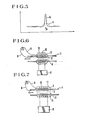
- Fig. 5 is a diagrammatic illustration of the relationship between the distance from a leak point and the voltage level developed;
- Fig. 6 is a schematic cross-sectional view of a gas leak detector according to a further embodiment of this invention; and
- Fig. 7 is a schematic cross-sectional view of a gas leak detector according to a still further embodiment of this invention.
- In this invention, as illustrated cross-sectionally in Fig. 1,
electrodes solid electrolyte 1 which is principally made of Zr02, for example, Zr02-Y203 or Zr02-CaO system. Of theelectrodes electrode 3 provided on the inner wall is applied with a catalytic layer 4 comprising, for example, V2O5-MoO3 supported on γ-Al2O3. - Incidentally, a suitable catalytic system may be readily selected depending on the type of a gas to be detected. In the case of detecting leak of a halogenated hydrocarbon gas represented by CC12F2, CHCIF2 or the like, use of the aforementioned V2O5-MoO3 supported on y-A1203 promises excellent selectivity to the target gas because the oxygen-ion conductive solid electrolyte will develop electromotive forces of the opposite polarity when brought into contact with other organic gases such as CO, C2HSOH and the like.
- When the above-mentioned catalytic layer formed of V2O5-MoO3 supported on y-A1203 is employed, it is preferred to use vanadium (V) in an amount ranging from 0.1 to 50 wt % of the y-A1203 support and molybdenum (Mo) in such an amount as to make the atomic ratio of molybdenum to vanadium be 0.05N0.6. Extremely high sensitivity is available particularly when V=10 wt % and MoN=1/10.
- The
electrodes 2, are connected to a voltmeter V via respective leads 5 and 6. - Using, as an example, a catalyst formed of V205-Mo03 supported on y-A1203, various gases were brought into contact with an oxygen-ion conductive solid electrolyte to determine the polarities of the thus-developed -electromotive forces. Results are shown in the following table.

- On the other hand, the oxygen partial pressure on the
electrode 2 provided on the outer wall of the oxygen-ion conductive solid electrolyte remains practically constant since theelectrode 2 is in direct contact with the atmosphere without catalytic layer. - Namely, in a gas leak detector according to this invention, a target gas is subjected to decomposition upon contact with the catalytic layer 4 while it is introduced into the hollow part of the tubular oxygen-ion conductive solid electrolyte and then charged out of the hollow part. Here, the decomposition results in the consumption of at least a part of oxygen in air, which has been introduced together with the target gas, and oxygen which has been adsorbed in the catalytic layer and porous electrode, thereby leading to a lowered oxygen partial pressure in the vicinity of the electrode on the inner wall of the solid electrolyte.
- As a result, a difference in oxygen partial pressure arises between the
electrode 3 on the inner wall and theelectrode 2 on the outer wall, thereby generating an electromotive force. - A heater 7 is supplied with energy from a
supply 8. The heater 7 may be of any type so long as it can heat the oxygen-ion conductive solid electrolyte to a predetermined temperature. It may for example be arranged near the outer circumference of the detector as illustrated in Fig. 1. Alternatively, it may be provided within the hollow part of the tubular oxygen-ion conductive solid electrolyte (not shown). It is however preferable, from the practical viewpoint, to provide the-heater on the surface of the electrode on the outer wall by burying the -heater-in an- inorganic-cement containing principally at least one of aluminum phosphate and sodium silicate. Use of aluminum phosphate and/or sodium silicate as cement is advantageous because it exhibits excellent adhesiveness to the electrode on the outer wall (or the oxygen-ion conductive solid electrolyte) upon coating same, it is converted to a porous structure having superior gas permeability after dried and sintered, and it maintains a high degree of adhesive strength stably. - On the other hand, the electrode on the outer wall of the tubular oxygen-ion conductive solid electrode, which electrode is brought into contact with a reference gas in the present invention, can be usually maintained in an exposed state to air as shown in Fig. 1. Namely, when comparing the oxygen partial pressure in the interior of the tubular electrolyte with that outside the same tubular electrolyte (i.e., in the atmosphere) as in the present invention, the electrode outside the tubular electrolyte is substantially free from the influence of each target gas. Therefore, the surrounding atmosphere of air may be utilized as the reference gas. If a still higher degree of sensitivity is desired, it may be effective to provide a
cover 10 as cross-sectionally depicted in Fig. 2 so as to prevent theelectrode 2 on the outer wall from being in direct contact with the target gas. Incidentally, thecover 10 may be made of any material such as metal, ceramics or the like so long as the material does not affect adversely on the detection of gas leak. It may be of any configurations suitable to avoid or suppress the direct contact of the target gas to theelectrode 2 on the outer wall. - Preferred embodiments of this invention will hereinafter be described by the following Examples:
- In the structure illustrated as a cross-sectionally in Fig. 1, Zr02 containing 5N8 mol % of Y203 was used as the oxygen-ion conductive
solid electrolyte 1. Platinum paste was baked on theelectrodes electrode 3 on the inner wall. The thus-fabricated detector was heated to about 450°C to determine the detectable lower concentration limit for each of CC12F2 and CHCIF2 as halogenated hydrocarbon gases. - As readily envisaged from Fig. 3, the detectable lower concentration limit for CC12F2 (represented by the curve a) was 6x10⁻⁶ cm3s. On the other hand, CHCIF2 had the detectable lower concentration limit at 8x10⁻⁶ cm3/s (not shown in the diagram).
- A gas leak detector having a prior art structure was also fabricated for the sake of comparison. Namely, as shown cross-sectionally- in Fig. 4,
electrodes 22; 23 were provided respectively on both surfaces of an oxygen-ion conductivesolid electrolyte 21 and a catalytic layer 24 was applied on the surface of theelectrode 22. A measurement was carried out with the gas leak detector in the same manner as in Example 1, theelectrodes - As illustrated in Fig. 2, a
metallic cover 10 was provided with the detector of Example 1 so as to minimize the chance of the target gas to be brought into contact with theelectrode 2 on the outer wall. The thus-fabricated gas leak detector showed the same sensitivity as represented by the curve b in Fig. 3 when the detector was used in a stationary state as in Example 1. However, distinct differences arose in both sensitivity and resolving power between the detector of Example 1 and that of the present example when the detector was scanned along a carrier pipe to suck the target gas as indicated by arrows in Figs. 1 and 2. Results of the above experiment are shown in Fig. 5, in which output signals produced upon contact with the target gas are plotted along the vertical axis while various points along the carrier pipe for the target gas are plotted along the horizontal axis. Letter A indicates the point of gas leak. In Fig. 5, the curve a represents results obtained using the detector of Example 1 and the curve b shows measurement results obtained with the detector of Example 2. - As apparent from the above results, both output and resolving power upon detecting gas leak are improved by the provision of the
cover 10 as in Example 2. - As cross-sectionally illustrated in Fig. 6, a gas leak detector of the same structure as that shown in Fig. 1 was fabricated by providing a
heater 12 on the outer surface of the detector in such a fashion that it was buried in aninorganic cement 11 consisting principally of at least either one of aluminum phosphate and sodium silicate. The thus-fabricated detector showed the same sen- . sitivity as the detector of Example 1. It exhibited excellent physical strength, notably superior resistance to vibrations when employed at high temperatures. - As cross-sectionally shown in Fig. 7, the detector of Example 3 was provided with a
catalytic layer 13 by packing the same catalyst as that employed in Example 1 in a hollow space corresponding to theelectrode 3 on the inner wall. - The thus-fabricated detector showed better detection sensitivity than the detector of Example 3, as indicated by the curve d in Fig. 3. However, it required somewhat longer response time.
- Needless to say, the cover, heater, catalytic layer and other components or parts of the gas leak detector according to this invention can be modified in configuration, materials, etc. as desired, within the scope of the appended claims.
Claims (5)
Applications Claiming Priority (2)
| Application Number | Priority Date | Filing Date | Title |
|---|---|---|---|
| JP150795/81 | 1981-09-25 | ||
| JP56150795A JPS5853752A (en) | 1981-09-25 | 1981-09-25 | Detecting element for gas leak |
Publications (3)
| Publication Number | Publication Date |
|---|---|
| EP0075835A2 EP0075835A2 (en) | 1983-04-06 |
| EP0075835A3 EP0075835A3 (en) | 1983-12-14 |
| EP0075835B1 true EP0075835B1 (en) | 1986-11-20 |
Family
ID=15504594
Family Applications (1)
| Application Number | Title | Priority Date | Filing Date |
|---|---|---|---|
| EP82108705A Expired EP0075835B1 (en) | 1981-09-25 | 1982-09-21 | Gas leak detector |
Country Status (6)
| Country | Link |
|---|---|
| US (1) | US4470882A (en) |
| EP (1) | EP0075835B1 (en) |
| JP (1) | JPS5853752A (en) |
| KR (1) | KR870000260B1 (en) |
| AU (1) | AU541920B2 (en) |
| DE (1) | DE3274387D1 (en) |
Families Citing this family (9)
| Publication number | Priority date | Publication date | Assignee | Title |
|---|---|---|---|---|
| US4674321A (en) * | 1985-12-06 | 1987-06-23 | Ceramatec, Inc. | Leak detector |
| JPH01137853A (en) * | 1987-11-25 | 1989-05-30 | Toshiba Corp | Communication control system |
| US5284569A (en) * | 1990-10-18 | 1994-02-08 | Leybold Inficon Inc. | Miniature gas sensor |
| DE19960174A1 (en) * | 1999-12-14 | 2001-06-28 | Leybold Vakuum Gmbh | Leak detection and leak detection methods and devices suitable for carrying out these methods |
| KR100981321B1 (en) * | 2010-04-07 | 2010-09-10 | 한국기계연구원 | A gas sensor and method for manufacturing thereof |
| US10488065B2 (en) | 2014-12-17 | 2019-11-26 | Carrier Corporation | Leak detection unit for refrigerant system |
| CN106644823B (en) * | 2016-12-21 | 2023-03-28 | 山西大学 | Air tightness testing device and method for coal wall coating |
| US11635339B2 (en) * | 2020-03-13 | 2023-04-25 | Honeywell International Inc. | Gas leakage monitoring system |
| CN115060426A (en) * | 2022-08-16 | 2022-09-16 | 江苏东海半导体股份有限公司 | IGBT sealing performance detection device and detection method |
Family Cites Families (16)
| Publication number | Priority date | Publication date | Assignee | Title |
|---|---|---|---|---|
| NL6901021A (en) * | 1969-01-22 | 1970-07-24 | ||
| DE1930880B2 (en) * | 1969-06-18 | 1980-02-21 | Chemische Werke Huels Ag, 4370 Marl | Process for the production of iso- and / or terephthalic acid dinitriles |
| US3981785A (en) * | 1969-07-18 | 1976-09-21 | Westinghouse Electric Corporation | Electrochemical sensor for reactive gas mixtures |
| US3650934A (en) * | 1969-11-14 | 1972-03-21 | Westinghouse Electric Corp | Oxygen control and measuring apparatus |
| US3871981A (en) * | 1971-09-01 | 1975-03-18 | Bailey Meter Co | In-situ oxygen detector |
| DE2322986A1 (en) * | 1973-05-08 | 1974-11-28 | Gerhard Laier | Hydrocarbon determination in water - by measuring hydrogen/water ratio in solid electrolyte cell |
| US3936794A (en) * | 1974-06-27 | 1976-02-03 | Ford Motor Company | Exhaust gas sensor probe |
| US4059628A (en) * | 1974-12-26 | 1977-11-22 | E. I. Du Pont De Nemours And Company | Preparation of aromatic amines |
| FR2348487A1 (en) * | 1976-04-16 | 1977-11-10 | Renault | Exhaust gas analysis system for IC engine - uses open solid electrolyte detector pipe mounted inside exhaust pipe |
| US4113745A (en) * | 1977-08-29 | 1978-09-12 | The Dow Chemical Company | Catalyst for and method of producing maleic anhydride |
| JPS584985B2 (en) * | 1978-05-10 | 1983-01-28 | 株式会社日立製作所 | gas detection element |
| US4269737A (en) * | 1978-07-25 | 1981-05-26 | Exxon Research & Engineering Company | Method for preparing a group IVB, VB or VIB metal oxide on inorganic refractory oxide support catalyst and the product prepared by said method |
| DD138245B1 (en) * | 1978-08-30 | 1980-12-10 | Moebius Hans Heinrich | DEVICE FOR GAS ANALYSIS WITH GALVANIC FIXED TECTROLYTIC CELLS |
| JPS55132947A (en) * | 1979-04-04 | 1980-10-16 | Ngk Insulators Ltd | Detecting method of halogen gas density and device thereof |
| JPS56150749A (en) * | 1980-04-23 | 1981-11-21 | Ricoh Co Ltd | Electrophotographic receptor |
| US4407778A (en) * | 1980-09-25 | 1983-10-04 | Tokyo Shibaura Denki Kabushiki Kaisha | Freon gas detecting element |
-
1981
- 1981-09-25 JP JP56150795A patent/JPS5853752A/en active Granted
-
1982
- 1982-09-17 AU AU88514/82A patent/AU541920B2/en not_active Ceased
- 1982-09-20 US US06/419,627 patent/US4470882A/en not_active Expired - Fee Related
- 1982-09-21 EP EP82108705A patent/EP0075835B1/en not_active Expired
- 1982-09-21 DE DE8282108705T patent/DE3274387D1/en not_active Expired
- 1982-09-25 KR KR8204328A patent/KR870000260B1/en active
Also Published As
| Publication number | Publication date |
|---|---|
| KR840001715A (en) | 1984-05-16 |
| DE3274387D1 (en) | 1987-01-08 |
| US4470882A (en) | 1984-09-11 |
| JPH0134339B2 (en) | 1989-07-19 |
| EP0075835A2 (en) | 1983-04-06 |
| JPS5853752A (en) | 1983-03-30 |
| EP0075835A3 (en) | 1983-12-14 |
| AU8851482A (en) | 1983-03-31 |
| KR870000260B1 (en) | 1987-02-21 |
| AU541920B2 (en) | 1985-01-31 |
Similar Documents
| Publication | Publication Date | Title |
|---|---|---|
| KR0169126B1 (en) | Miniature gas sensor | |
| EP0075835B1 (en) | Gas leak detector | |
| CA2507428C (en) | Hydrogen gas sensor | |
| US5284569A (en) | Miniature gas sensor | |
| EP0262223B1 (en) | Detector for gas chromatograph | |
| Matsuura | New developments and applications of gas sensors in Japan | |
| JPS62503187A (en) | Detection part of surface ionization sensor of halogen gas leak detector | |
| Huang et al. | Design of an electrochemiluminescence detection system through the regulation of charge density in a microchannel | |
| Maclay et al. | Microfabricated amperometric gas sensors | |
| AU671381B2 (en) | Method and apparatus for testing refrigerant | |
| US4189355A (en) | Method for detection of fluctuation in air/fuel ratio of air-fuel mixture fed to internal combustion engine | |
| US4499054A (en) | Cation emission type halogenated hydrocarbon gas detecting element | |
| KR20010045820A (en) | Toxic gas measuring apparatus and an apparatus for controlling the amount of fuel to use according to the measured toxic gases from vehicles | |
| US20060213772A1 (en) | Sensing element and method of making | |
| US20040226832A1 (en) | Methods of making gas sensors and sensors formed therefrom | |
| US20060016687A1 (en) | Methods of making a ceramic device and a sensor element | |
| EP1656553B1 (en) | Electrochemical method | |
| KR102699679B1 (en) | Complex gas sensor of semiconductor type and combustion type | |
| Kaminski et al. | Oxygen in Gases | |
| JP3647492B2 (en) | Gas sensor | |
| JPS644619B2 (en) | ||
| JPH04286949A (en) | Gas sensor element | |
| Cobb et al. | A novel humidity sensor using yb-doped SrCeO 3 ionic conductor with a au-pd filter | |
| Chviruk et al. | Mass transfer in amperometric gas sensors | |
| SU1193563A1 (en) | Oxygen solion |
Legal Events
| Date | Code | Title | Description |
|---|---|---|---|
| PUAI | Public reference made under article 153(3) epc to a published international application that has entered the european phase |
Free format text: ORIGINAL CODE: 0009012 |
|
| AK | Designated contracting states |
Designated state(s): DE GB NL |
|
| PUAL | Search report despatched |
Free format text: ORIGINAL CODE: 0009013 |
|
| AK | Designated contracting states |
Designated state(s): DE GB NL |
|
| 17P | Request for examination filed |
Effective date: 19840221 |
|
| RAP1 | Party data changed (applicant data changed or rights of an application transferred) |
Owner name: KABUSHIKI KAISHA TOSHIBA |
|
| GRAA | (expected) grant |
Free format text: ORIGINAL CODE: 0009210 |
|
| STAA | Information on the status of an ep patent application or granted ep patent |
Free format text: STATUS: THE PATENT HAS BEEN GRANTED |
|
| AK | Designated contracting states |
Kind code of ref document: B1 Designated state(s): DE GB NL |
|
| REF | Corresponds to: |
Ref document number: 3274387 Country of ref document: DE Date of ref document: 19870108 |
|
| PLBE | No opposition filed within time limit |
Free format text: ORIGINAL CODE: 0009261 |
|
| 26N | No opposition filed | ||
| GBPC | Gb: european patent ceased through non-payment of renewal fee | ||
| GBDL | Gb: delete "european patent ceased" from journal |
Free format text: 5178, PAGE 1477 |
|
| PGFP | Annual fee paid to national office [announced via postgrant information from national office to epo] |
Ref country code: DE Payment date: 19910930 Year of fee payment: 10 |
|
| PGFP | Annual fee paid to national office [announced via postgrant information from national office to epo] |
Ref country code: GB Payment date: 19920911 Year of fee payment: 11 |
|
| PGFP | Annual fee paid to national office [announced via postgrant information from national office to epo] |
Ref country code: NL Payment date: 19920930 Year of fee payment: 11 |
|
| PG25 | Lapsed in a contracting state [announced via postgrant information from national office to epo] |
Ref country code: DE Effective date: 19930602 |
|
| PG25 | Lapsed in a contracting state [announced via postgrant information from national office to epo] |
Ref country code: GB Effective date: 19930921 |
|
| PG25 | Lapsed in a contracting state [announced via postgrant information from national office to epo] |
Ref country code: NL Effective date: 19940401 |
|
| NLV4 | Nl: lapsed or anulled due to non-payment of the annual fee | ||
| GBPC | Gb: european patent ceased through non-payment of renewal fee |
Effective date: 19930921 |