EP0075672B1 - Anordnung eines nahtlosen Farbbandes mit Halteband und Verfahren zu seiner Herstellung - Google Patents
Anordnung eines nahtlosen Farbbandes mit Halteband und Verfahren zu seiner Herstellung Download PDFInfo
- Publication number
- EP0075672B1 EP0075672B1 EP82106658A EP82106658A EP0075672B1 EP 0075672 B1 EP0075672 B1 EP 0075672B1 EP 82106658 A EP82106658 A EP 82106658A EP 82106658 A EP82106658 A EP 82106658A EP 0075672 B1 EP0075672 B1 EP 0075672B1
- Authority
- EP
- European Patent Office
- Prior art keywords
- ribbon
- trailer
- leader
- substrate
- foil
- Prior art date
- Legal status (The legal status is an assumption and is not a legal conclusion. Google has not performed a legal analysis and makes no representation as to the accuracy of the status listed.)
- Expired
Links
Images

Classifications
-
- B—PERFORMING OPERATIONS; TRANSPORTING
- B41—PRINTING; LINING MACHINES; TYPEWRITERS; STAMPS
- B41J—TYPEWRITERS; SELECTIVE PRINTING MECHANISMS, i.e. MECHANISMS PRINTING OTHERWISE THAN FROM A FORME; CORRECTION OF TYPOGRAPHICAL ERRORS
- B41J31/00—Ink ribbons; Renovating or testing ink ribbons
- B41J31/10—Ink ribbons having arrangements to facilitate threading through a machine
-
- B—PERFORMING OPERATIONS; TRANSPORTING
- B41—PRINTING; LINING MACHINES; TYPEWRITERS; STAMPS
- B41J—TYPEWRITERS; SELECTIVE PRINTING MECHANISMS, i.e. MECHANISMS PRINTING OTHERWISE THAN FROM A FORME; CORRECTION OF TYPOGRAPHICAL ERRORS
- B41J33/00—Apparatus or arrangements for feeding ink ribbons or like character-size impression-transfer material
- B41J33/003—Ribbon spools
- B41J33/006—Arrangements to attach the ribbon to the spool
Definitions
- the invention relates to typewriter/printer ribbon structures and manufacturing methods therefor and, more particularly, to a spliceless ribbon structure having leader and trailer and to a method of manufacture therefor.
- the substrate material such as a cast polyethylene is coated in large wide rolls with an ink material which is capable of being transferred from the substrate to the printed page by impact.
- this material is fed from the large wide rolls referred to as jumbo rolls, it is slit by a slitter and wound upon individual ribbon cores for subsequent use on a printer or typewriter. After an appropriate amount of ribbon has been wound upon the cores, the slitter is stopped and a segment of the ribbon stock which remains unslit is cut out and a non-inked material typically spliced into the gap to form a leader and trailer.
- This material is then passed through the slitter to subdivide it in width to the width of the ribbons being spooled and is wound partially onto the spool in the slitter.
- the ribbon stock and slitter are stopped and the ribbon spool wound with ribbon and leader are severed near the center of the leader/ trailerfilm.
- a portion of the material accompanies the ribbon on the spools, thus forming a spliced- on leader.
- the remaining portion of the leader/ trailer material which has been severed is then attached to new empty spools to form the spliced- on trailer and it is then wound along with ribbon onto the spools to the desired diameter.
- the cutting of the ribbon stock and the subsequent splicing in and slitting of the leader/ trailer material may cause misalignment, which may cause the spools not to wind uniformly. When this occurs, the ribbon spool and the ribbon thereon are rejected as improperly wound and discarded, thus increasing the cost of the ultimate product. Additionally, if leader/trailer material is not firmly taped into the bulk ribbon strand, the bond may break, requiring rethreading of the slitter and resulting in the subsequent loss of a large number of ribbons in production.
- the spliced-in leader/ trailer is a length of adhesive tape attached to the non-inked face of the ribbon at the end thereof, thus leaving the inked face of the ribbon exposed.
- the spliced-in leader/ trailer is a composite of foils or webs, which requires the assembly of several separate webs, which composite must then be adhesively attached to the end of the ribbon.
- US-A-3,286,808 thus illustrates spliced-in leaders/ trailers which require the assembly of a plurality of webs or foils in precise controlled locations.
- a ribbon leader is normally a spliced-in assembly and serves to carry the attaching tape, which is used to connect the start of the ribbon to the take-up spool, and further serves to provide a clean handling length of material to protect the operator from ink contamination during the loading of the ribbon into the typewriter.
- a ribbon trailer is a spliced-in assembly of tape and film and serves to carry the attaching tape which is used to attach the end of the ribbon assembly to the supply hub.
- the spliced-in trailer assembly typically provides a visual end of ribbon warning via its contrasting color and further provides a threshold print interruption feature to terminate printing before ribbon feed becomes inhibited by the lack of additional ribbon supply.
- An interruption in feed can have the undesirable effect of causing light and dark characters which require subsequent correction before typing can be continued.
- One common undesirable effect of a contrasting colored trailer material is that the typewriter can impact the material upon ribbon depletion, thereby causing a transferring of the colored material to the typed page which usually cannot be corrected.
- the present invention provides a spliceless ribbon structure and a method of manufacture therefor.
- the ribbon structure according to the invention is of the type having an ink impermeable substrate having a first side and a second side and a marking ink on said second side forming a composite, said composite having an inner end and an outer end when wound on a hub to form a ribbon disc with an uninked leader on the outer end of said wound composite and an uninked trailer on said inner end.
- the ribbon structure of the invention is characterized in that said leader and trailer comprise a laminate of an uninked material adhesively attached throughout their entire length on said second side.
- the method of making and winding small typewriter/printer useable rolls of ribbon having an ink impermeable substrate and a marking material on one surface of said substrate from bulk rolls of said ribbon, and applying adhesively to said ribbon an uninked foil is characterized in that a predetermined length of said foil is applied to said ribbon across its complete width over said marking material to form a laminate, subsequently slitting said ribbon and said laminate, winding said slit ribbon and laminate on a plurality of spools to form typewriter/printer useable rolls of ribbon with a leader and trailer, and severing said rolls within said laminate length.
- the adhesion of the leader/trailer to the ink face of the ribbon structure insures that the ink is encapsulated in the laminate and is thus not capable of transfer to the paper when impacted by a printing element. Inasmuch as there is no colored material available to the typed sheet, no transfer may occur and thereby spoil the text appearance on the typed sheet when the ribbon is exhausted.
- the width of the trailer may be adjusted to provide an adequately long trailer to insure typed interruption before the trailer is pulled from the spool of the ribbon core.
- the length of the leader may be adjusted to provide a length of ink encapsulated ribbon to provide clean loading of the ribbon when required.
- foils as laminates instead of spliced-in leader and trailer assemblies as in the prior art, maintains spliceless integrity of the ribbon for guiding, feeding and slitting and thereby insures enhanced alignment upon passage through the slitter and a reduced number of defective ribbon rolls due to skewed ribbon and pulled apart splices.
- the apparatus and structure are such that the slitting and spooling operations are greatly enhanced due to the elimination of the need to remove a segment or span of the bulk ribbon.
- a further advantage is that the ribbon of the invention provides a precise end of ribbon warning without the possibility of a transfer of either a partial ink layer or color from a trailer thereby spoiling the appearance of the typed copy.
- the ribbon stock 10 comprising an impermeable substrate 12 and an ink layer 14 will pass through a leader/ trailer station 16 illustrated in Fig. 1.
- the ribbon 10 is positioned between an upper platen 18 and a lower platen 20.
- the platens 18 and 20 are flat plates which are moveable into a position where they forcibly engage opposite sides of the ribbon 10.
- platens 18 and 20 are withdrawn and held withdrawn by platen lift control 22 and 24.
- a space sufficient to traverse the ribbon web 10 with carrier 26 is provided.
- Carrier 26 carries thereon at least a roller 28 around which is passed a web of adhesive tape 30 and in the disclosed embodiment carries three rollers 28 and tape 30.
- Adhesive tape 30 is provided from supply spool 32 and accumulated after use on take-up spool 34.
- Take-up spool 34 is powered by drive 36 to wind the consumed ribbon onto the take-up spool 34 as carrier 26 translates from left to right across the path of ribbon 10.
- the translation of carrier 26 will place roller 28 in a position as indicated by the phantom lines with tape span 30 passing around roller 28.
- platen 18 is lowered by platen lift control 22 to provide a solid backing for ribbon 10.
- substrate 12 and ink layer 14 are trapped between adhesive tape 30 and platen 18 with platen 18 providing a resistive backing force against ribbon 10.
- Carrier 26 is caused to translate from right to left by carrier drive 38 which drives the carrier in any conventional manner.
- This drive may be a chain drive, rack and pinion drive, leadscrew drive or any other suitable approach and is not a significant basis for this invention and, therefore, need not be described in detail.
- Foil composite 42 is formed by unreeling foil 56 and at the same time pulling therewith a tape 60 which has adhesive on both sides.
- Foil 56 is provided with an adhesive material on one side which forms the inner surface of the wrap on its supply spool 50.
- platen lift control 24 may be energized to raise platen 20 to trap foil composite 42 and ribbon 10 between platen 20 and platen 18 and forcibly engage the adhesive side of foil composite 42 with the ink side 14 of ribbon 10.
- Foil composite 42 may then be severed by any conventional technique such as hot wire, shear or other severing device.
- the structure of the leader/ trailer has at this point been fabricated together with the ribbon 10 to form a composite laminate.
- This laminate may then be passed onto subsequent processing stations such as the slitter and winder of the type manufactured by The John Dusenbery Corporation of Randolph, New Jersey.
- the ribbon stock 10 is adhesively engaged by the adhesive tape 30 as the tape 30 passes about roller 28.
- Rollers 28 are conveniently commonly mounted upon shaft 52 for ease in movement and control.
- ink layer 14 is adhesively removed from substrate 12 and carried on the adhesive face of tape 30.
- the ribbon stock 10 is as it appears in Fig. 3, greatly enlarged.
- the channels formed into ink layer 14 are those regions of the ink material which were removed by adhesive engagement with tape 30 as described with reference to Fig. 2.
- the carrier 26 in Fig. 1 moves toward the right to pull the tape from engagement with ink layer 14 and remove the ink layer 14 from substrate 12, it also pulls foil composite 42 transverse to the length of ribbon stock 10.
- Foil composite 42 is illustrated in Fig. 3. There may be separate foil composites for the leader and trailer. Face 54 of foil 56 is adhesive and is positioned to engage the ink side 14 of ribbon stock 10. Where foil 56 overlies a region where the ink layer 14 has been disrupted and removed, the adhesive surface 54 of foil 56 will then engage the substrate 12 for a firm adhesive attachment. Carried on the non-adhesive face 58 of foil 56 is a double-faced adhesive tape 60. Double-faced adhesive tape 60 will adhere on one side to the non-adhesive face 58 of foil 56 and will expose the second adhesive face 62 of tape 60.
- the leader portion 64 is primarily for purposes of attaching the end of the ribbon to the take-up spool during final assembly of the ribbon assembly.
- the trailer 66 is primarily adapted for attachment to the supply spool with tape 60 and the extending out away from the supply spool for a finite distance of a non-inked surface on foil 56 to provide an encapsulated ink length of trailer from which printing cannot be accomplished through ink transfer.
- the portion 64 can be lengthened to form an encapsulated ink length of ribbon for clean handling, if required.
- the substrate 12 is transparent to translucent and with the removal of the ink layer 14 in finite bands transverse to the bulk ribbon stock 10, a window 68 of some transmissability to light is created and overlaid subsequently with foil 56.
- This gap in the ink layer and thus the transmissability of light therethrough provides a visual warning to the operator that the end of the ink layer is imminent.
- the length 70 of ribbon stock 10 is waste and results from characteristics of the techniques employed to slit the ribbon stock 10 and may vary from slitting machine type to slitting machine type.
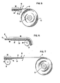
- the ribbon 10 has been wound upon the spool and the leader severed from the bulk supply of the ribbon stock.
- the advantage of extending the foil 56 to either side of the region from which the ink layer 14 had been removed is that upon the complete sandwiching of the foil composite with the ribbon stock 10, a laminated structure results which has substantially enhanced rigidity and handling characteristics than that of the exceedingly thin film ribbon 10 by itself.
- Fig. 6 illustrates the trailer portion 66 of the ribbon 10 adhesively attached by tape 60 to the supply spool 72, with the foil 56 extending leftward from the point of attachment and overlying the ink layer 14 to provide a non- printing surface in conjunction with the end of ribbon warning window 68.
- the length of trailer portion 66 may be varied according to the desires of the person implementing the ribbon spool assembly and the needs of the ribbon feed mechanism upon which the ribbon assembly will be utilized.
- take-up spool 74 is illustrated in bonding contact with the adhesive strip 60 on leader structure 64.
- the extension of foil 56 on one or both sides of the zone from which the ink layer 14 had been removed from substrate 12 adds rigidity through the laminating characteristics to the ribbon 10.
- the foil 56 may be enlarged to provide any desired extended length toward the supply spool. It is also possible that an additional zone of ink removal may be desirable proximate to the edge of foil 56 if the length of the leader portion 64 is extended.
- the leader and trailer structure In addition to simplifying the assembly of the ribbon structure with trailers and leaders, the leader and trailer structure also permit substantially enhanced possibilities for full and complete automation of the assembly of the leader/trailer composite to the bulk ribbon web 10.
- the control of gripper control 44, drives 36 and 38, and platen lift controls 22 and 24 are all conventional automated controls and may be implemented in any one of a number of possible ways according to the desires of the implementer.
- leader laminate section 64 it will display sufficient rigidity for automated handling and assembly, should that function be desirable from the producer's standpoint, inasmuch as substantially better handling characteristics are provided by the laminate than would be by a segment of the exceedingly thin film ribbon 10 in the absence of said laminate structure. Characteristically, the laminate provides a type of bi-metallic action wherein the end will project from the ribbon circumference in a semi-rigid fashion.
Landscapes
- Impression-Transfer Materials And Handling Thereof (AREA)
- Document Processing Apparatus (AREA)
- Joining Of Building Structures In Genera (AREA)
- Machines For Manufacturing Corrugated Board In Mechanical Paper-Making Processes (AREA)
- Mechanical Coupling Of Light Guides (AREA)
- Metal Extraction Processes (AREA)
- Branch Pipes, Bends, And The Like (AREA)
- Accessory Devices And Overall Control Thereof (AREA)
- Printers Characterized By Their Purpose (AREA)
- Joining Of Corner Units Of Frames Or Wings (AREA)
- Separation Using Semi-Permeable Membranes (AREA)
- Golf Clubs (AREA)
Claims (7)
Priority Applications (1)
| Application Number | Priority Date | Filing Date | Title |
|---|---|---|---|
| AT82106658T ATE23488T1 (de) | 1981-09-29 | 1982-07-23 | Anordnung eines nahtlosen farbbandes mit halteband und verfahren zu seiner herstellung. |
Applications Claiming Priority (2)
| Application Number | Priority Date | Filing Date | Title |
|---|---|---|---|
| US30679181A | 1981-09-29 | 1981-09-29 | |
| US306791 | 1981-09-29 |
Publications (3)
| Publication Number | Publication Date |
|---|---|
| EP0075672A2 EP0075672A2 (de) | 1983-04-06 |
| EP0075672A3 EP0075672A3 (en) | 1984-06-06 |
| EP0075672B1 true EP0075672B1 (de) | 1986-11-12 |
Family
ID=23186857
Family Applications (1)
| Application Number | Title | Priority Date | Filing Date |
|---|---|---|---|
| EP82106658A Expired EP0075672B1 (de) | 1981-09-29 | 1982-07-23 | Anordnung eines nahtlosen Farbbandes mit Halteband und Verfahren zu seiner Herstellung |
Country Status (9)
| Country | Link |
|---|---|
| EP (1) | EP0075672B1 (de) |
| JP (1) | JPS5863492A (de) |
| AT (1) | ATE23488T1 (de) |
| AU (1) | AU553869B2 (de) |
| BR (1) | BR8204990A (de) |
| CA (1) | CA1191473A (de) |
| DE (1) | DE3274219D1 (de) |
| ES (1) | ES277011Y (de) |
| MX (1) | MX152423A (de) |
Families Citing this family (2)
| Publication number | Priority date | Publication date | Assignee | Title |
|---|---|---|---|---|
| US4933315A (en) * | 1987-02-20 | 1990-06-12 | Dai Nippon Insatsu Kabushiki Kaisha | Heat transfer sheet |
| US6089768A (en) * | 1998-05-05 | 2000-07-18 | Printronix, Inc. | Print ribbon feeder and detection system |
Family Cites Families (5)
| Publication number | Priority date | Publication date | Assignee | Title |
|---|---|---|---|---|
| BE431113A (de) * | 1938-11-29 | |||
| US2789677A (en) * | 1955-11-14 | 1957-04-23 | Smith Corona Inc | Carbon ribbon supply for typewriters |
| US3286808A (en) * | 1964-06-05 | 1966-11-22 | Ibm | Typewriter ribbon combination |
| JPS4995716A (de) * | 1973-01-19 | 1974-09-11 | ||
| JPS5270007U (de) * | 1975-11-18 | 1977-05-25 |
-
1982
- 1982-07-23 AT AT82106658T patent/ATE23488T1/de active
- 1982-07-23 EP EP82106658A patent/EP0075672B1/de not_active Expired
- 1982-07-23 DE DE8282106658T patent/DE3274219D1/de not_active Expired
- 1982-08-04 CA CA000408728A patent/CA1191473A/en not_active Expired
- 1982-08-17 AU AU87233/82A patent/AU553869B2/en not_active Ceased
- 1982-08-25 BR BR8204990A patent/BR8204990A/pt unknown
- 1982-09-08 JP JP57155307A patent/JPS5863492A/ja active Granted
- 1982-09-28 ES ES1982277011U patent/ES277011Y/es not_active Expired
- 1982-09-29 MX MX194582A patent/MX152423A/es unknown
Also Published As
| Publication number | Publication date |
|---|---|
| ATE23488T1 (de) | 1986-11-15 |
| DE3274219D1 (en) | 1987-01-02 |
| ES277011Y (es) | 1985-02-01 |
| AU553869B2 (en) | 1986-07-31 |
| AU8723382A (en) | 1983-04-14 |
| MX152423A (es) | 1985-07-12 |
| JPS5863492A (ja) | 1983-04-15 |
| ES277011U (es) | 1984-07-01 |
| BR8204990A (pt) | 1983-08-02 |
| EP0075672A3 (en) | 1984-06-06 |
| JPH0260514B2 (de) | 1990-12-17 |
| CA1191473A (en) | 1985-08-06 |
| EP0075672A2 (de) | 1983-04-06 |
Similar Documents
| Publication | Publication Date | Title |
|---|---|---|
| EP0278663B1 (de) | Verfahren zum Formen von Polsterstücken | |
| US4475830A (en) | Spliceless ribbon structure having leader and trailer and method of manufacture therefor | |
| JP3500342B2 (ja) | ラベル列の供給方法と、当該方法に使用するラベルサポート | |
| US6972066B2 (en) | Roll, roll production apparatus and method for producing roll | |
| EP0291767B1 (de) | Längsschneid- und Aufwickelmaschine | |
| JP6040694B2 (ja) | 画像形成装置 | |
| EP0075672B1 (de) | Anordnung eines nahtlosen Farbbandes mit Halteband und Verfahren zu seiner Herstellung | |
| US10384900B2 (en) | Dispenser apparatus and method of use for laminating and dispensing transfer tape in a paper web turn-up system | |
| CN210236602U (zh) | 一种凹印铜版纸的剥离连线机构 | |
| EP0876960A2 (de) | Etikettbehandlungssystem | |
| US10442648B2 (en) | Dispenser apparatus and method of use for laminating and dispensing transfer tape in a paper web turn-up system | |
| JP3666325B2 (ja) | ワイヤーハーネス用巻回シートの供給方法及びその供給装置 | |
| KR20020085809A (ko) | 식별 코딩을 갖는 스트립 또는 테이프 형태의 매체로제조된 롤 및 그 제조 공정 | |
| JPH0789154A (ja) | ラベル印字装置 | |
| US5632849A (en) | Tab applicator for log roll winders | |
| JP2006213010A (ja) | テープカセット | |
| JP3800814B2 (ja) | テープカセット | |
| JP2791739B2 (ja) | 非粘着テープ体の巻取方法 | |
| US6033508A (en) | Method and apparatus for manufacturing ribbon roll | |
| US6224277B1 (en) | Ink ribbon with adhesive for attaching end of ribbon to supply roll | |
| JP2992411B2 (ja) | 転写用リボンカセット | |
| EP0876909A1 (de) | Trennfolienfreie Etiketten und Herstellungsverfahren | |
| JPH09268498A (ja) | プリント用紙及びその製造方法 | |
| JP2001071574A (ja) | ロール紙及び該ロール紙を使用するプリンタ | |
| JPH01299153A (ja) | スリッタマシン |
Legal Events
| Date | Code | Title | Description |
|---|---|---|---|
| PUAI | Public reference made under article 153(3) epc to a published international application that has entered the european phase |
Free format text: ORIGINAL CODE: 0009012 |
|
| AK | Designated contracting states |
Designated state(s): AT BE CH DE FR GB IT LI NL SE |
|
| 17P | Request for examination filed |
Effective date: 19830722 |
|
| PUAL | Search report despatched |
Free format text: ORIGINAL CODE: 0009013 |
|
| AK | Designated contracting states |
Designated state(s): AT BE CH DE FR GB IT LI NL SE |
|
| AK | Designated contracting states |
Designated state(s): AT BE CH DE FR GB IT LI NL SE |
|
| GRAA | (expected) grant |
Free format text: ORIGINAL CODE: 0009210 |
|
| AK | Designated contracting states |
Kind code of ref document: B1 Designated state(s): AT BE CH DE FR GB IT LI NL SE |
|
| REF | Corresponds to: |
Ref document number: 23488 Country of ref document: AT Date of ref document: 19861115 Kind code of ref document: T |
|
| REF | Corresponds to: |
Ref document number: 3274219 Country of ref document: DE Date of ref document: 19870102 |
|
| ET | Fr: translation filed | ||
| ITF | It: translation for a ep patent filed |
Owner name: IBM - DR. ARRABITO MICHELANGELO |
|
| PLBE | No opposition filed within time limit |
Free format text: ORIGINAL CODE: 0009261 |
|
| STAA | Information on the status of an ep patent application or granted ep patent |
Free format text: STATUS: NO OPPOSITION FILED WITHIN TIME LIMIT |
|
| 26N | No opposition filed | ||
| ITTA | It: last paid annual fee | ||
| REG | Reference to a national code |
Ref country code: FR Ref legal event code: GC |
|
| REG | Reference to a national code |
Ref country code: CH Ref legal event code: PUE Owner name: LEXMARK INTERNATIONAL, INC. |
|
| REG | Reference to a national code |
Ref country code: GB Ref legal event code: 732 |
|
| REG | Reference to a national code |
Ref country code: FR Ref legal event code: TP |
|
| ITPR | It: changes in ownership of a european patent |
Owner name: CESSIONE;LEXMARK INTERNATIONAL INC. |
|
| NLS | Nl: assignments of ep-patents |
Owner name: LEXMARK INTERNATIONAL, INC. TE LEXINGTON, KENTUCKY |
|
| ITPR | It: changes in ownership of a european patent |
Owner name: PEGNO;J.P. MORGAN DELAWARE |
|
| REG | Reference to a national code |
Ref country code: CH Ref legal event code: PVP Owner name: J.P. MORGAN DELAWARE |
|
| PGFP | Annual fee paid to national office [announced via postgrant information from national office to epo] |
Ref country code: FR Payment date: 19920610 Year of fee payment: 11 |
|
| PGFP | Annual fee paid to national office [announced via postgrant information from national office to epo] |
Ref country code: DE Payment date: 19920611 Year of fee payment: 11 |
|
| PGFP | Annual fee paid to national office [announced via postgrant information from national office to epo] |
Ref country code: SE Payment date: 19920615 Year of fee payment: 11 Ref country code: CH Payment date: 19920615 Year of fee payment: 11 |
|
| PGFP | Annual fee paid to national office [announced via postgrant information from national office to epo] |
Ref country code: BE Payment date: 19920617 Year of fee payment: 11 Ref country code: AT Payment date: 19920617 Year of fee payment: 11 |
|
| PGFP | Annual fee paid to national office [announced via postgrant information from national office to epo] |
Ref country code: GB Payment date: 19920626 Year of fee payment: 11 |
|
| PGFP | Annual fee paid to national office [announced via postgrant information from national office to epo] |
Ref country code: NL Payment date: 19920731 Year of fee payment: 11 |
|
| PG25 | Lapsed in a contracting state [announced via postgrant information from national office to epo] |
Ref country code: GB Effective date: 19930723 Ref country code: AT Effective date: 19930723 |
|
| PG25 | Lapsed in a contracting state [announced via postgrant information from national office to epo] |
Ref country code: SE Effective date: 19930724 |
|
| PG25 | Lapsed in a contracting state [announced via postgrant information from national office to epo] |
Ref country code: LI Effective date: 19930731 Ref country code: CH Effective date: 19930731 Ref country code: BE Effective date: 19930731 |
|
| BERE | Be: lapsed |
Owner name: LEXMARK INTERNATIONAL INC. Effective date: 19930731 |
|
| PG25 | Lapsed in a contracting state [announced via postgrant information from national office to epo] |
Ref country code: NL Effective date: 19940201 |
|
| NLV4 | Nl: lapsed or anulled due to non-payment of the annual fee | ||
| GBPC | Gb: european patent ceased through non-payment of renewal fee |
Effective date: 19930723 |
|
| PG25 | Lapsed in a contracting state [announced via postgrant information from national office to epo] |
Ref country code: FR Effective date: 19940331 |
|
| REG | Reference to a national code |
Ref country code: CH Ref legal event code: PL |
|
| PG25 | Lapsed in a contracting state [announced via postgrant information from national office to epo] |
Ref country code: DE Effective date: 19940401 |
|
| REG | Reference to a national code |
Ref country code: FR Ref legal event code: ST |
|
| EUG | Se: european patent has lapsed |
Ref document number: 82106658.6 Effective date: 19940210 |