EP0075641A2 - Composite material - Google Patents
Composite material Download PDFInfo
- Publication number
- EP0075641A2 EP0075641A2 EP82100692A EP82100692A EP0075641A2 EP 0075641 A2 EP0075641 A2 EP 0075641A2 EP 82100692 A EP82100692 A EP 82100692A EP 82100692 A EP82100692 A EP 82100692A EP 0075641 A2 EP0075641 A2 EP 0075641A2
- Authority
- EP
- European Patent Office
- Prior art keywords
- latticework
- composite material
- material according
- plastic film
- film
- Prior art date
- Legal status (The legal status is an assumption and is not a legal conclusion. Google has not performed a legal analysis and makes no representation as to the accuracy of the status listed.)
- Granted
Links
Images


Classifications
-
- B—PERFORMING OPERATIONS; TRANSPORTING
- B32—LAYERED PRODUCTS
- B32B—LAYERED PRODUCTS, i.e. PRODUCTS BUILT-UP OF STRATA OF FLAT OR NON-FLAT, e.g. CELLULAR OR HONEYCOMB, FORM
- B32B15/00—Layered products comprising a layer of metal
- B32B15/04—Layered products comprising a layer of metal comprising metal as the main or only constituent of a layer, which is next to another layer of the same or of a different material
- B32B15/08—Layered products comprising a layer of metal comprising metal as the main or only constituent of a layer, which is next to another layer of the same or of a different material of synthetic resin
-
- B—PERFORMING OPERATIONS; TRANSPORTING
- B32—LAYERED PRODUCTS
- B32B—LAYERED PRODUCTS, i.e. PRODUCTS BUILT-UP OF STRATA OF FLAT OR NON-FLAT, e.g. CELLULAR OR HONEYCOMB, FORM
- B32B27/00—Layered products comprising a layer of synthetic resin
- B32B27/12—Layered products comprising a layer of synthetic resin next to a fibrous or filamentary layer
-
- B—PERFORMING OPERATIONS; TRANSPORTING
- B32—LAYERED PRODUCTS
- B32B—LAYERED PRODUCTS, i.e. PRODUCTS BUILT-UP OF STRATA OF FLAT OR NON-FLAT, e.g. CELLULAR OR HONEYCOMB, FORM
- B32B15/00—Layered products comprising a layer of metal
- B32B15/02—Layer formed of wires, e.g. mesh
-
- B—PERFORMING OPERATIONS; TRANSPORTING
- B32—LAYERED PRODUCTS
- B32B—LAYERED PRODUCTS, i.e. PRODUCTS BUILT-UP OF STRATA OF FLAT OR NON-FLAT, e.g. CELLULAR OR HONEYCOMB, FORM
- B32B15/00—Layered products comprising a layer of metal
- B32B15/04—Layered products comprising a layer of metal comprising metal as the main or only constituent of a layer, which is next to another layer of the same or of a different material
- B32B15/043—Layered products comprising a layer of metal comprising metal as the main or only constituent of a layer, which is next to another layer of the same or of a different material of metal
-
- B—PERFORMING OPERATIONS; TRANSPORTING
- B32—LAYERED PRODUCTS
- B32B—LAYERED PRODUCTS, i.e. PRODUCTS BUILT-UP OF STRATA OF FLAT OR NON-FLAT, e.g. CELLULAR OR HONEYCOMB, FORM
- B32B7/00—Layered products characterised by the relation between layers; Layered products characterised by the relative orientation of features between layers, or by the relative values of a measurable parameter between layers, i.e. products comprising layers having different physical, chemical or physicochemical properties; Layered products characterised by the interconnection of layers
- B32B7/04—Interconnection of layers
- B32B7/12—Interconnection of layers using interposed adhesives or interposed materials with bonding properties
-
- B—PERFORMING OPERATIONS; TRANSPORTING
- B32—LAYERED PRODUCTS
- B32B—LAYERED PRODUCTS, i.e. PRODUCTS BUILT-UP OF STRATA OF FLAT OR NON-FLAT, e.g. CELLULAR OR HONEYCOMB, FORM
- B32B2310/00—Treatment by energy or chemical effects
- B32B2310/04—Treatment by energy or chemical effects using liquids, gas or steam
Definitions
- the invention relates to a composite material of the type explained in the preamble of claim 1.
- Composite materials are known in a wide variety of material combinations for different purposes.
- the invention has for its object to provide a composite material that is simple in construction, inexpensive to manufacture and can be used for a wide variety of uses.
- the lattice structure designed as a supporting structure ensures the necessary strength, while the flexible plastic film closes the lattice openings.
- a particularly advantageous embodiment can be seen from subclaim 4.
- the meshwork inserted between the plastic film and the lattice works to support the film.
- the lattice therefore only needs to be dimensioned according to the forces to be absorbed.
- the plastic films applied on both sides are connected to each other not only at the edge, but also between the grid or mesh openings, the durability of the composite material is further increased.
- Claim 10 describes a particularly preferred production method for the composite material according to the invention.
- this method can run more or less automatically.
- Claims 13 and 14 describe an advantageous production line for producing the composite material according to the invention from latticework and film, in which these plastic films are shrunk on.
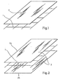
- FIG. 1 An exploded view of a composite material according to the invention can be seen in FIG. 1. It consists of a latticework 1 made of crossed metal bars and a flexible plastic film 2 covering the lattice openings.
- the latticework 1 consists of metal bars connected at right angles crossed. The diameter of the rods and their spacing from one another depends on the later intended use, ie on the forces to be absorbed, the required dimensional stability and the thickness of the film.
- the plastic film 2 was placed on a pre-cut piece of the latticework 1 of the appropriate size and connected to it. The connection was made either by shrinking or welding, by gluing, for example by means of adhesive strips, or by mechanical means, for example by means of binding wire or staples.
- the plastic films 2a and 2b are commercially available shrink films which are stretched over the latticework 1 by the action of heat and are connected to one another and to the lattice work 1.
- the connection points are mainly on the edge and in each or in selected grid! openings.
- Fig. 3 shows a composite material, which is composed of the latticework 1 made of metal and a plastic film 2.
- a mesh 3 is inserted between the latticework 1 and the plastic film 2.
- the mesh 3 consists of a commercially available wire mesh.
- the wire mesh is much finer compared to the latticework 1. Since both the later static forces and the forces that occur during shrinking are completely absorbed by the latticework 1, the mesh 3 can be relatively thin and flexible.
- the mesh 3 takes over the support of the plastic film 2, so that it can hardly be pierced.
- the latticework 1 can be dimensioned solely to absorb static forces, ie the distance and diameter of the metal rods used and their connection depends on the expected load.
- the three materials 1, 2, 3 used are connected to one another analogously as described under FIG. 1.
- FIG. 4 shows a composite material which represents a combination of FIGS. 2 and 3.
- the plastic films 2a and 2b are in turn commercially available shrink films which are connected to one another and to latticework 1 and mesh 2 in the manner described. They firmly enclose the latticework 1 and the mesh 3 between them and thus bring about a non-slip securing of the position of the individual materials of the composite without further precautions.
- FIG. 5 A preferred production line for producing the composite material according to the invention is described in FIG. 5.
- the lower plastic film 2b, the latticework 1, the meshwork 3 and the upper plastic film 2a are pulled together from their respective stocks.
- the supplies are shown as supply rolls 5 to 8. However, it is also possible to pull off the films from rolls, with grids and meshwork being fed as webs.
- the parallel superimposed, mutually aligned layers of the materials used then pass through a shrinking and welding device 9.
- the two plastic films 2a and 2b are joined together at the longitudinal edges by the action of heat, so that they do not retract.
- the shrinking and welding device 9 works with upper and lower rows of flames, each on the upper and the lower plastic film 2a and 2b are directed.
- the stresses in the pre-stretched shrink films are released so that they cool down after cooling.
- the web of the finished composite material is then cut to the required size. Since both foils are connected to one another over the entire surface of the web in the lattice or mesh spaces, the web can be cut as desired without the foils retracting at the cut edges.
- the latticework 1 and also the meshwork 3 can be straightened or smoothed as required, before they are covered with film, by appropriate devices, not shown.
- one or more pairs of pressure rollers made of felt or similar material can also be provided, which additionally press the still soft foils against one another and against the latticework and meshwork.
- the meshwork can consist of a wide variety of materials and types of weave.
- a commercial fly gauze made of metal wires or plastic is just as suitable as one of the usual wire meshes with coarser or finer meshes in the most diverse ties.
- the latticework can be made from thicker, rigid or thinner, bendable bars with a larger or smaller mesh spacing, at right angles or diagonally crossed, braided or superimposed.
- the film can be made from a wide variety of plastics in different thicknesses, colored or transparent.
Abstract
Description
Die Erfindung bezieht sich auf einen Verbundwerkstoff der im Oberbegriff von Anspruch 1 erläuterten Art.The invention relates to a composite material of the type explained in the preamble of
Verbundwerkstoffe sind in den unterschiedlichsten Materialkombinationen für unterschiedliche Verwendungszwecke bekannt.Composite materials are known in a wide variety of material combinations for different purposes.
Die meisten dieser Verbundwerkstoffe sind relativ kompliziert aufgebaut und kostenintensiv im Materialverbrauch und Herstellung.Most of these composites have a relatively complex structure and are costly to use and manufacture.
Der Erfindung liegt die Aufgabe zugrunde, einen Verbundwerkstoff bereitzustellen, der einfach aufgebaut, kostengünstig herstellbar und-für die unterschiedlichsten Verwendungszwecke einsetzbar ist.The invention has for its object to provide a composite material that is simple in construction, inexpensive to manufacture and can be used for a wide variety of uses.
Die Aufgabe wird durch die kennzeichnenden Merkmale des Hauptanspruchs gelöst.The object is achieved by the characterizing features of the main claim.
Das als Traggerüst ausgestaltete Gitterwerk sorgt für die notwendige Festigkeit, während die flexible Kunststoffolie die Gitteröffnungen schließt.The lattice structure designed as a supporting structure ensures the necessary strength, while the flexible plastic film closes the lattice openings.
Besondere Vorteile werden gemäß Anspruch 2 dadurch erreicht, daß das Gitterwerk von beiden Seiten mit der Kunststoffolie bedeckt wird, die das Gitterwerk zwischen sich einschließen. Auf diese Weise wird eine erhöhte Festigkeit und ein verbesserter Korrosionsschutz des Gitterwerkstoffes erreicht.Particular advantages are achieved according to
Die Ausgestaltung des Gitterwerkes 3 aus gekreuzten Metallstäben gibt dem fertigen Verbundwerkstoff die nötige Steifigkeit und Festigkeit.The design of the
Ein besonders vorteilhaftes Ausführungsbeispiel ist aus dem Unteranspruch 4 ersichtlich. Das zwischen die Kunststoffolie und dem Gitterwerk eingeschobene Maschenwerk übernimmt die Unterstützung der Folie. Das Gitterwerk braucht somit lediglich entsprechend den aufzunehmenden Kräften dimensioniert zu werden.A particularly advantageous embodiment can be seen from subclaim 4. The meshwork inserted between the plastic film and the lattice works to support the film. The lattice therefore only needs to be dimensioned according to the forces to be absorbed.
Die Verwendung einer Schrumpfstoffolie nach Anspruch 5 er- leichtert die Herstellung des erfindungsgemäßen Verbundwerkstoffes. iThe use of a shrink material film according to claim 5 facilitates the production of the composite material according to the invention. i
Die Ansprüche 6 bis 8 beschreiben weitere vorteilhafte Befestigungsmöglichkeiten der Kunststoffolie.Claims 6 to 8 describe further advantageous fastening options for the plastic film.
Wenn nach Anspruch 9 die beidseitig aufgebrachten Kunststoffolien nicht nur am Rand, sondern auch zwischen den Gitter- bzw. Maschenöffnungen miteinander verbunden sind, wird die Haltbarkeit des Verbundwerkstoffes weiter erhöht.If, according to claim 9, the plastic films applied on both sides are connected to each other not only at the edge, but also between the grid or mesh openings, the durability of the composite material is further increased.
Anspruch 10 beschreibt ein besonders bevorzugstes Herstellungsverfahren für den erfindungsgemäßen Verbundwerkstoff.Claim 10 describes a particularly preferred production method for the composite material according to the invention.
Durch die Ausgestaltung nach Anspruch 11 kann dieses Verfahren mehr oder weniger automatisch ablaufen.Due to the configuration according to claim 11, this method can run more or less automatically.
Vor Auflegen der Kunststoffolie empfiehlt es sich, gemäß Anspruch 12, durch eine Richteinrichtung das Gitterwerk zu glätten.Before placing the plastic film, it is advisable, according to claim 12, to smooth the latticework by means of a straightening device.
Die Ansprüche 13 und 14 beschreiben eine vorteilhafte Fertigungsstrasse zum Herstellen des erfindungsgemäßen Verbundwerkstoffes aus Gitterwerk und Folie, bei dem diese Kunststoffolien aufgeschrumpft werden.Claims 13 and 14 describe an advantageous production line for producing the composite material according to the invention from latticework and film, in which these plastic films are shrunk on.
Die Erfindung wird nachstehend anhand der Zeichnungen näher erläutert.The invention is explained in more detail below with reference to the drawings.
Es zeigen:
- Fig. 1 eine auseinandergezogene Darstellung des erfindungsgemäßen Verbundwerkstoffes mit einer Folie,
- Fig. 2 eine auseinandergezogene Darstellung des erfindungsgemäßen Verbundwerkstoffes mit beidseitiger Folie,
- Fig. 3 eine auseinandergezogene Darstellung des erfindungsgemäßen Verbundwerkstoffes mit einer Folie und zwischengelegtem Maschenwerk,
- Fig. 4 eine auseinandergezogene Darstellung des Verbundwerkstoffes aus Fig. 3 mit zwei Folien, und
- Fig. 5 eine schematische Darstellung einer Fertigungsstrasse für den erfindungsgemäßen Verbundwerkstoff.
- 1 is an exploded view of the composite material according to the invention with a film,
- 2 is an exploded view of the composite material according to the invention with double-sided film,
- 3 is an exploded view of the composite material according to the invention with a film and interposed meshwork,
- Fig. 4 is an exploded view of the composite material from Fig. 3 with two foils, and
- 5 shows a schematic representation of a production line for the composite material according to the invention.
In Fig. 1 ist ein erfindungsgemäßer Verbundwerkstoff in auseinandergezogener Darstellung ersichtlich. Er besteht aus einem Gitterwerk 1 aus gekreuzten Metallstäben und einer die Gitteröffnungen bedeckenden flexiblen Kunststoffolie 2. Das Gitterwerk 1 besteht aus rechtwinklig gekreuzt verbundenen Metallstäben. Der Durchmesser der Stäbe und ihr Abstand zueinander richtet sich nach dem späteren Verwendungszweck, d.h. je nach den aufzunehmenden Kräften, der geforderten Formstabilität und der Dicke der Folie. Die Kunststoffolie 2 wurde auf ein vorgeschnittenes Stück des Gitterwerks 1 in entsprechender Größe aufgelegt und mit ihm verbunden. Die Verbindung erfolgte entweder durch Schrumpfen oder Schweißen, durch Kleben, beispielsweise durch Klebestreifen, oder durch mechanische Mittel, beispielsweise durch Bindedraht oder Heftklammern.An exploded view of a composite material according to the invention can be seen in FIG. 1. It consists of a
In Fig. 2 ist ein Verbundwerkstoff ersichtlich, bei dem das Gitterwerk 1 von einer oberen 2a und einer unteren 2b Kunststoffolie 2 eingeschlossen ist. Die Kunststofffolien 2a und 2b sind handelsübliche Schrumpffolien, die durch Wärmeeinwirkung über das Gitterwerk 1 gespannt und miteinander und mit dem Gitterwerk 1 verbunden sind. Die Verbindungsstellen liegen hauptsächlich am Rand und in jeder bzw. in ausgewählten Gitter- ! öffnungen.2 shows a composite material in which the
Fig. 3 zeigt einen Verbundwerkstoff, der aus dem Gitterwerk 1 aus Metall und einer Kunststoffolie 2 zusammengesetzt ist. Zwischen das Gitterwerk 1 und die Kunststoffolie 2 ist ein Maschenwerk 3 eingelegt. Das Maschenwerk 3 besteht aus einem handelsüblichen Drahtgitter. Das Drahtgitter ist gegenüber dem Gitterwerk 1 wesentlich feinmaschiger. Da sowohl die späteren statischen Kräfte als auch die Kräfte, die beim Schrumpfen auftreten, vollständig vom Gitterwerk 1 aufgenommen werden, kann das Maschenwerk 3 relativ dünn und flexibel sein. Das Maschenwerk 3 übernimmt die Unterstützung der Kunststoffolie 2, so daß diese kaum noch durchstoßen werden kann. Das Gitterwerk 1 kann demnach allein zur Aufnahme von statischen Kräften dimensioniert werden, d.h. der Abstand und der Durchmesser der verwendeten Metallstäbe und ihre Verbindung richtet sich nach der zu erwartenden Belastung. Die drei verwendeten Werkstoffe 1, 2, 3 werden analog wie unter Fig. 1 beschrieben miteinander verbunden.Fig. 3 shows a composite material, which is composed of the
In Fig. 4 ist ein Verbundwerkstoff ersichtlich, der eine Kombination aus Fig. 2 und Fig. 3 darstellt. Die Kunststoffolien 2a und 2b sind wiederum handelsübliche Schrumpffolien, die in der beschriebenen Weise miteinander und mit Gitterwerk 1 und Maschenwerk 2 verbunden werden. Sie schließen das Gitterwerk 1 und das Maschenwerk 3 fest zwischen sich ein und bewirken damit eine rutschfeste Lagesicherung der einzelnen Werkstoffe des Verbundes ohne weitere Vorkehrungen.FIG. 4 shows a composite material which represents a combination of FIGS. 2 and 3. The
In Fig. 5 ist eine bevorzugte Fertigungsstrasse zur Herstellung des erfindungsgemäßen Verbundwerkstoffes beschrieben. Auf einer bahnförmigen Transporteinrichtung 4 werden übereinander die untere Kunststoffolie 2b, das Gitterwerk 1, das Maschenwerk 3 und die obere Kunststoff folie 2a gemeinsam aus ihren jeweiligen Vorräten abgezogen. Die Vorräte sind als Vorratsrollen 5 bis 8 dargestellt. Es können aber auch nur die Folien von Rollen abgezogen werden, wobei Gitter und Maschenwerk als Bahnen zugestellt werden. Die parallel übereinanderliegenden, zueinander ausgerichteten Schichten der verwendeten Werkstoffe durchlaufen anschließend eine Schrumpf-und Schweißvorrichtung 9. In dieser Vorrichtung 9 werden durch Wärmeeinwirkung die beiden Kunststoffolien 2a und 2b an den Längskanten miteinander verbunden, so daß sie sich nicht zurückziehen. Die Schrumpf- und Schweißvorrichtung 9 arbeitet mit oberen und unteren Flammenreihen, die auf jeweils die obere und die untere Kunststoffolie 2a und 2b gerichtet sind. Durch in Richtung auf die zu verbindenden Werkstoffe eingeblasene Luft, die durch die Flammenreihen erhitzt wird, werden die Folien erweicht und gegeneinander gedrückt, so daß sie in den Gitter- bzw. Maschenzwischenräumen fest miteinander verschweißt werden. Gleichzeitig werden die Spannungen in den vorgereckten Schrumpffolien gelost, so daß sie sich nach dem Abkühlen. fest: um Metallgitter und Maschenwerk legen und beide zwischen sich einschließen. Anschließend wird die Bahn des fertigen Verbundwerkstoffes auf die benötigte Größe abgelängt. Da beide Folien über die gesamte Oberfläche der Bahn jeweils in den Gitter- bzw. Maschenzwischenräumen miteinander verbunden sind, kann die Bahn beliebig geschnitten werden, ohne daß sich die Folien an den Schnittkanten zurückziehen. Das Gitterwerk 1 und auch das Maschenwerk 3 können nach Bedarf, bevor sie mit Folie belegt werden durch entsprechende, nicht dargestellte Einrichtungen gerichtet bzw. geglättet werden. Unmittelbar hinter der Schrumpf- und Schweißvorrichtung können außerdem ein oder mehrere Paare Andrückrollen 'aus Filz oder ähnlichem Material vorgesehen werden, die die noch weichen Folien zusätzlich gegeneinander und gegen Gitterwerk und Maschenwerk drücken.A preferred production line for producing the composite material according to the invention is described in FIG. 5. On a web-shaped transport device 4, the lower
Die Erfindung ist nicht auf die beschriebenen Ausführungsbeispiele beschränkt. Die in den einzelnen Figuren beschriebenen Merkmale können untereinander ausgetauscht werden. Auch die verwendeten Werkstoffe können von der beschriebenen Form abweichen. Beispielsweise kann das Maschenwerk aus den unterschiedlichsten Materialien und Bindungsarten bestehen. So ist eine handelsübliche Fliegengaze aus Metalldrähten oder Kunststoff ebenso geeignet, wie einer der üblichen Maschendrähte mit gröberen oder feineren Maschen in den unterschiedlichsten Bindungen. Das Gitterwerk kann je nach Verwendungszweck aus dickeren, starren oder dünneren, biegbaren Stäben, mit größerem oder kleinerem Maschenabstand, rechtwinklig oder schräg gekreuzt, geflochten oder übereinandergelegt hergestellt werden. Die Folie kann aus den verschiedensten Kunststoffen in verschiedenen Stärken, eingefärbt oder durchsichtig hergestellt werden.The invention is not restricted to the exemplary embodiments described. The features described in the individual figures can be interchanged. The materials used can also deviate from the form described. For example, the meshwork can consist of a wide variety of materials and types of weave. A commercial fly gauze made of metal wires or plastic is just as suitable as one of the usual wire meshes with coarser or finer meshes in the most diverse ties. Depending on the intended use, the latticework can be made from thicker, rigid or thinner, bendable bars with a larger or smaller mesh spacing, at right angles or diagonally crossed, braided or superimposed. The film can be made from a wide variety of plastics in different thicknesses, colored or transparent.
Claims (16)
Priority Applications (9)
| Application Number | Priority Date | Filing Date | Title |
|---|---|---|---|
| AT82100692T ATE36829T1 (en) | 1981-09-28 | 1982-02-01 | COMPOSITE. |
| GR67965A GR78207B (en) | 1981-09-28 | 1982-04-22 | |
| DK198782A DK164399C (en) | 1981-09-28 | 1982-05-04 | ARMED LAMINATE AND PROCEDURE AND APPARATUS FOR MANUFACTURING THE LAMINATE |
| MX19319382A MX159292A (en) | 1981-09-28 | 1982-06-17 | IMPROVEMENTS IN LAMINATED STRUCTURAL AND PROCEDURE FOR ITS OBTAINING |
| BR8204234A BR8204234A (en) | 1981-09-28 | 1982-07-21 | COMPOUND MATERIAL WELL AS A PROCESS AND DEVICE FOR ITS MANUFACTURING |
| AU86244/82A AU551877B2 (en) | 1981-09-28 | 1982-07-21 | Compound material |
| ES516031A ES516031A0 (en) | 1981-09-28 | 1982-09-28 | COMPOSITE MATERIAL. |
| ES1983273577U ES273577Y (en) | 1981-09-28 | 1983-07-15 | GRID DEVICE |
| ES1983276647U ES276647Y (en) | 1981-09-28 | 1983-12-30 | PERFECTED GRID DEVICE. |
Applications Claiming Priority (4)
| Application Number | Priority Date | Filing Date | Title |
|---|---|---|---|
| DE19813138513 DE3138513A1 (en) | 1981-09-28 | 1981-09-28 | Process and apparatus for covering flat bar structures on both sides with plastic films |
| DE3138513 | 1981-09-28 | ||
| DE3142148 | 1981-10-23 | ||
| DE19813142148 DE3142148A1 (en) | 1981-10-23 | 1981-10-23 | Composite material |
Publications (3)
| Publication Number | Publication Date |
|---|---|
| EP0075641A2 true EP0075641A2 (en) | 1983-04-06 |
| EP0075641A3 EP0075641A3 (en) | 1984-04-18 |
| EP0075641B1 EP0075641B1 (en) | 1988-08-31 |
Family
ID=25796378
Family Applications (1)
| Application Number | Title | Priority Date | Filing Date |
|---|---|---|---|
| EP82100692A Expired EP0075641B1 (en) | 1981-09-28 | 1982-02-01 | Composite material |
Country Status (4)
| Country | Link |
|---|---|
| EP (1) | EP0075641B1 (en) |
| CA (1) | CA1201371A (en) |
| DE (1) | DE3278972D1 (en) |
| NZ (1) | NZ201447A (en) |
Cited By (8)
| Publication number | Priority date | Publication date | Assignee | Title |
|---|---|---|---|---|
| US4525964A (en) * | 1982-05-28 | 1985-07-02 | Adolf Diethelm | Structural element for the manufacture of casings, wall disks, boxes and such articles |
| FR2645493A1 (en) * | 1989-04-11 | 1990-10-12 | Renault | AUTOMOTIVE BODY PIECE WITH COMPOSITE STRUCTURE IN PARTICULAR HOOD |
| EP0892127A1 (en) | 1997-07-15 | 1999-01-20 | Willibald Fischer | Arrangement for inducing cracks |
| NL1010629C2 (en) * | 1998-11-23 | 2000-05-24 | Besouw Kunststoffen B V Van | Packaging material resistant to e.g. rodents, comprises a synthetic film reinforced with a flat wire cloth |
| DE202009004864U1 (en) | 2009-05-26 | 2009-08-27 | Peca-Verbundtechnik Gmbh | Permanent formwork with swiveling bottom part |
| EP2857605A1 (en) | 2013-10-07 | 2015-04-08 | Peca Verbundtechnik GmbH | Formwork element |
| DE102017117375A1 (en) | 2017-08-01 | 2019-02-07 | Max Frank Gmbh & Co. Kg | Shuttering element for concrete construction |
| DE102009003749B4 (en) | 2009-04-06 | 2020-07-23 | Max Frank Gmbh & Co. Kg | Composite material for creating a fire protection joint |
Families Citing this family (1)
| Publication number | Priority date | Publication date | Assignee | Title |
|---|---|---|---|---|
| DE102004056332B4 (en) * | 2004-11-22 | 2007-10-31 | Peca-Verbundtechnik Gmbh | Use of a composite material for the insulation of sound and vibration |
Citations (5)
| Publication number | Priority date | Publication date | Assignee | Title |
|---|---|---|---|---|
| US2742391A (en) * | 1946-08-30 | 1956-04-17 | Flex O Glass Inc | Method of making reinforced laminated material |
| US3627613A (en) * | 1969-05-23 | 1971-12-14 | Monsanto Co | Continuous process for preparing composites in sheet form |
| FR2348804A1 (en) * | 1976-04-20 | 1977-11-18 | Trefilunion | Hot gas jets for lamination of mesh between thermoplastic films - to provide heat and pressure for rapid throughput lamination |
| FR2354183A1 (en) * | 1976-06-08 | 1978-01-06 | Weihrauch Drahtwerke | Linked machines for producing metal mesh covered with plastic sheet - for lining mines, earth banks etc. |
| GB2060486A (en) * | 1979-10-18 | 1981-05-07 | Chavannes Marc A | Method and Apparatus for Making Reinforced Laminated and Corrugated Materials |
-
1982
- 1982-02-01 DE DE8282100692T patent/DE3278972D1/en not_active Expired
- 1982-02-01 EP EP82100692A patent/EP0075641B1/en not_active Expired
- 1982-06-24 CA CA000405885A patent/CA1201371A/en not_active Expired
- 1982-07-30 NZ NZ201447A patent/NZ201447A/en unknown
Patent Citations (5)
| Publication number | Priority date | Publication date | Assignee | Title |
|---|---|---|---|---|
| US2742391A (en) * | 1946-08-30 | 1956-04-17 | Flex O Glass Inc | Method of making reinforced laminated material |
| US3627613A (en) * | 1969-05-23 | 1971-12-14 | Monsanto Co | Continuous process for preparing composites in sheet form |
| FR2348804A1 (en) * | 1976-04-20 | 1977-11-18 | Trefilunion | Hot gas jets for lamination of mesh between thermoplastic films - to provide heat and pressure for rapid throughput lamination |
| FR2354183A1 (en) * | 1976-06-08 | 1978-01-06 | Weihrauch Drahtwerke | Linked machines for producing metal mesh covered with plastic sheet - for lining mines, earth banks etc. |
| GB2060486A (en) * | 1979-10-18 | 1981-05-07 | Chavannes Marc A | Method and Apparatus for Making Reinforced Laminated and Corrugated Materials |
Cited By (11)
| Publication number | Priority date | Publication date | Assignee | Title |
|---|---|---|---|---|
| US4525964A (en) * | 1982-05-28 | 1985-07-02 | Adolf Diethelm | Structural element for the manufacture of casings, wall disks, boxes and such articles |
| FR2645493A1 (en) * | 1989-04-11 | 1990-10-12 | Renault | AUTOMOTIVE BODY PIECE WITH COMPOSITE STRUCTURE IN PARTICULAR HOOD |
| EP0392904A1 (en) * | 1989-04-11 | 1990-10-17 | Regie Nationale Des Usines Renault | Body part for an automotive vehicle with a composite structure, in particular a hood |
| EP0892127A1 (en) | 1997-07-15 | 1999-01-20 | Willibald Fischer | Arrangement for inducing cracks |
| NL1010629C2 (en) * | 1998-11-23 | 2000-05-24 | Besouw Kunststoffen B V Van | Packaging material resistant to e.g. rodents, comprises a synthetic film reinforced with a flat wire cloth |
| DE102009003749B4 (en) | 2009-04-06 | 2020-07-23 | Max Frank Gmbh & Co. Kg | Composite material for creating a fire protection joint |
| DE202009004864U1 (en) | 2009-05-26 | 2009-08-27 | Peca-Verbundtechnik Gmbh | Permanent formwork with swiveling bottom part |
| EP2857605A1 (en) | 2013-10-07 | 2015-04-08 | Peca Verbundtechnik GmbH | Formwork element |
| DE102013111056A1 (en) | 2013-10-07 | 2015-04-09 | Peca - Verbundtechnik Gmbh | An element |
| RU2606892C2 (en) * | 2013-10-07 | 2017-01-10 | ПЕКА Фербундтекник ГмбХ | Method of making uneven concrete surfaces |
| DE102017117375A1 (en) | 2017-08-01 | 2019-02-07 | Max Frank Gmbh & Co. Kg | Shuttering element for concrete construction |
Also Published As
| Publication number | Publication date |
|---|---|
| EP0075641B1 (en) | 1988-08-31 |
| NZ201447A (en) | 1986-04-11 |
| CA1201371A (en) | 1986-03-04 |
| DE3278972D1 (en) | 1988-10-06 |
| EP0075641A3 (en) | 1984-04-18 |
Similar Documents
| Publication | Publication Date | Title |
|---|---|---|
| DE3247146C1 (en) | Method and device for the continuous production of laminated materials | |
| DE2236445C3 (en) | Base material for textile substitutes | |
| DE2823669C3 (en) | Heat-deformable synthetic resin laminated sheet and methods for deforming these sheets | |
| DE3801059C2 (en) | Repair patches for vehicle bodies | |
| DE2932698C2 (en) | Device for joining carrier mats and metal foil web sections in the course of the production of laminate panels | |
| EP3496936A1 (en) | Spar cap made of prefabricated elements with laid fabric and method for producing same | |
| DE2361828B2 (en) | Device for joining and forming a fabric from two or more layers of textile fiber fabric | |
| DE2356028B2 (en) | COVER WITH PERFORATED REINFORCEMENT EDGE AND PROCESS FOR THEIR PRODUCTION | |
| DE2825903B2 (en) | Device for folding several webs into one another | |
| EP0075641B1 (en) | Composite material | |
| DE2258369A1 (en) | PROCESS FOR CONTINUOUS SURFACE COATING OF A BASE LAYER | |
| DE2044696C2 (en) | Device for the continuous production of a flat composite web | |
| DE3117137C2 (en) | Preformed, self-supporting vehicle part, in particular vehicle roof lining | |
| DE2524155C2 (en) | Device for the continuous production of a pipe string with a longitudinal seam from a weldable web material | |
| DE3819362A1 (en) | WATERPROOF, WATER VAPOR-PERMEABLE INSERT FOR CLOTHING | |
| DE102007035780A1 (en) | Method for producing a foldable plate | |
| DE3621054A1 (en) | METHOD AND DEVICE FOR CONNECTING FLEXIBLE MATERIALS | |
| DE3142148A1 (en) | Composite material | |
| AT391292B (en) | METHOD FOR PRODUCING A SINGLE OR TWO-SIDED PUNCHING KNIFE FOR NON-METAL MATERIALS | |
| DE3041236A1 (en) | Solar heat collector with fluid chamber - has flexible base and cover plates with woven plastics pad between them | |
| DE2209764A1 (en) | LAMINATES, IN PARTICULAR MULTI-LAYER ADHESIVE FILM, AND METHOD OF MANUFACTURING | |
| DE2541667A1 (en) | METHOD OF MANUFACTURING PRINTED CIRCUIT BOARDS | |
| DE2811151C3 (en) | Process for the production of multilayer composite films | |
| DE968151C (en) | Reflector for irradiation facilities | |
| DE3030430A1 (en) | Torsionally rigid straight flexible plate - is corrugated in both longitudinal and transverse directions |
Legal Events
| Date | Code | Title | Description |
|---|---|---|---|
| PUAI | Public reference made under article 153(3) epc to a published international application that has entered the european phase |
Free format text: ORIGINAL CODE: 0009012 |
|
| AK | Designated contracting states |
Designated state(s): AT BE CH DE FR GB IT LI LU NL SE |
|
| PUAL | Search report despatched |
Free format text: ORIGINAL CODE: 0009013 |
|
| AK | Designated contracting states |
Designated state(s): AT BE CH DE FR GB IT LI LU NL SE |
|
| 17P | Request for examination filed |
Effective date: 19840605 |
|
| GRAA | (expected) grant |
Free format text: ORIGINAL CODE: 0009210 |
|
| AK | Designated contracting states |
Kind code of ref document: B1 Designated state(s): AT BE CH DE FR GB IT LI LU NL SE |
|
| REF | Corresponds to: |
Ref document number: 36829 Country of ref document: AT Date of ref document: 19880915 Kind code of ref document: T |
|
| ITF | It: translation for a ep patent filed |
Owner name: JACOBACCI & PERANI S.P.A. |
|
| GBT | Gb: translation of ep patent filed (gb section 77(6)(a)/1977) | ||
| REF | Corresponds to: |
Ref document number: 3278972 Country of ref document: DE Date of ref document: 19881006 |
|
| ET | Fr: translation filed | ||
| RAP2 | Party data changed (patent owner data changed or rights of a patent transferred) |
Owner name: KIRCHNER-CARL, ANGELIKA |
|
| REG | Reference to a national code |
Ref country code: CH Ref legal event code: PUE Owner name: ANGELIKA KIRCHNER-CARL |
|
| PLBE | No opposition filed within time limit |
Free format text: ORIGINAL CODE: 0009261 |
|
| STAA | Information on the status of an ep patent application or granted ep patent |
Free format text: STATUS: NO OPPOSITION FILED WITHIN TIME LIMIT |
|
| REG | Reference to a national code |
Ref country code: FR Ref legal event code: TP |
|
| 26N | No opposition filed | ||
| NLS | Nl: assignments of ep-patents |
Owner name: ANGELIKA KIRCHNER GEB. CARL TE PRESSIG, BONDSREPUB |
|
| REG | Reference to a national code |
Ref country code: GB Ref legal event code: 732 |
|
| ITPR | It: changes in ownership of a european patent |
Owner name: CESSIONE;ANGELIKA KIRCHNER - CARL |
|
| BECH | Be: change of holder |
Free format text: 880831 *KIRCHNER-CARL ANGELIKA |
|
| ITTA | It: last paid annual fee | ||
| EPTA | Lu: last paid annual fee | ||
| EAL | Se: european patent in force in sweden |
Ref document number: 82100692.1 |
|
| PGFP | Annual fee paid to national office [announced via postgrant information from national office to epo] |
Ref country code: GB Payment date: 20010125 Year of fee payment: 20 |
|
| PGFP | Annual fee paid to national office [announced via postgrant information from national office to epo] |
Ref country code: AT Payment date: 20010220 Year of fee payment: 20 |
|
| PGFP | Annual fee paid to national office [announced via postgrant information from national office to epo] |
Ref country code: SE Payment date: 20010221 Year of fee payment: 20 |
|
| PGFP | Annual fee paid to national office [announced via postgrant information from national office to epo] |
Ref country code: FR Payment date: 20010222 Year of fee payment: 20 Ref country code: BE Payment date: 20010222 Year of fee payment: 20 |
|
| PGFP | Annual fee paid to national office [announced via postgrant information from national office to epo] |
Ref country code: LU Payment date: 20010223 Year of fee payment: 20 |
|
| PGFP | Annual fee paid to national office [announced via postgrant information from national office to epo] |
Ref country code: NL Payment date: 20010227 Year of fee payment: 20 |
|
| PGFP | Annual fee paid to national office [announced via postgrant information from national office to epo] |
Ref country code: CH Payment date: 20010302 Year of fee payment: 20 |
|
| PGFP | Annual fee paid to national office [announced via postgrant information from national office to epo] |
Ref country code: DE Payment date: 20010329 Year of fee payment: 20 |
|
| BE20 | Be: patent expired |
Free format text: 20020201 *KIRCHNER-CARL ANGELIKA |
|
| REG | Reference to a national code |
Ref country code: GB Ref legal event code: IF02 |
|
| PG25 | Lapsed in a contracting state [announced via postgrant information from national office to epo] |
Ref country code: LI Free format text: LAPSE BECAUSE OF EXPIRATION OF PROTECTION Effective date: 20020131 Ref country code: GB Free format text: LAPSE BECAUSE OF EXPIRATION OF PROTECTION Effective date: 20020131 Ref country code: CH Free format text: LAPSE BECAUSE OF EXPIRATION OF PROTECTION Effective date: 20020131 |
|
| PG25 | Lapsed in a contracting state [announced via postgrant information from national office to epo] |
Ref country code: NL Free format text: LAPSE BECAUSE OF EXPIRATION OF PROTECTION Effective date: 20020201 Ref country code: LU Free format text: LAPSE BECAUSE OF EXPIRATION OF PROTECTION Effective date: 20020201 Ref country code: AT Free format text: LAPSE BECAUSE OF EXPIRATION OF PROTECTION Effective date: 20020201 |
|
| REG | Reference to a national code |
Ref country code: GB Ref legal event code: PE20 Effective date: 20020131 |
|
| REG | Reference to a national code |
Ref country code: CH Ref legal event code: PL |
|
| EUG | Se: european patent has lapsed |
Ref document number: 82100692.1 |
|
| NLV7 | Nl: ceased due to reaching the maximum lifetime of a patent |