EP0075572B1 - Conteneurs de fluides - Google Patents
Conteneurs de fluides Download PDFInfo
- Publication number
- EP0075572B1 EP0075572B1 EP19820900979 EP82900979A EP0075572B1 EP 0075572 B1 EP0075572 B1 EP 0075572B1 EP 19820900979 EP19820900979 EP 19820900979 EP 82900979 A EP82900979 A EP 82900979A EP 0075572 B1 EP0075572 B1 EP 0075572B1
- Authority
- EP
- European Patent Office
- Prior art keywords
- container according
- pressure
- fluid
- container
- tubular component
- Prior art date
- Legal status (The legal status is an assumption and is not a legal conclusion. Google has not performed a legal analysis and makes no representation as to the accuracy of the status listed.)
- Expired
Links
Images

Classifications
-
- F—MECHANICAL ENGINEERING; LIGHTING; HEATING; WEAPONS; BLASTING
- F17—STORING OR DISTRIBUTING GASES OR LIQUIDS
- F17C—VESSELS FOR CONTAINING OR STORING COMPRESSED, LIQUEFIED OR SOLIDIFIED GASES; FIXED-CAPACITY GAS-HOLDERS; FILLING VESSELS WITH, OR DISCHARGING FROM VESSELS, COMPRESSED, LIQUEFIED, OR SOLIDIFIED GASES
- F17C13/00—Details of vessels or of the filling or discharging of vessels
- F17C13/12—Arrangements or mounting of devices for preventing or minimising the effect of explosion ; Other safety measures
- F17C13/123—Arrangements or mounting of devices for preventing or minimising the effect of explosion ; Other safety measures for gas bottles, cylinders or reservoirs for tank vehicles or for railway tank wagons
-
- A—HUMAN NECESSITIES
- A62—LIFE-SAVING; FIRE-FIGHTING
- A62C—FIRE-FIGHTING
- A62C13/00—Portable extinguishers which are permanently pressurised or pressurised immediately before use
- A62C13/76—Details or accessories
-
- F—MECHANICAL ENGINEERING; LIGHTING; HEATING; WEAPONS; BLASTING
- F17—STORING OR DISTRIBUTING GASES OR LIQUIDS
- F17C—VESSELS FOR CONTAINING OR STORING COMPRESSED, LIQUEFIED OR SOLIDIFIED GASES; FIXED-CAPACITY GAS-HOLDERS; FILLING VESSELS WITH, OR DISCHARGING FROM VESSELS, COMPRESSED, LIQUEFIED, OR SOLIDIFIED GASES
- F17C1/00—Pressure vessels, e.g. gas cylinder, gas tank, replaceable cartridge
- F17C1/14—Pressure vessels, e.g. gas cylinder, gas tank, replaceable cartridge constructed of aluminium; constructed of non-magnetic steel
-
- F—MECHANICAL ENGINEERING; LIGHTING; HEATING; WEAPONS; BLASTING
- F17—STORING OR DISTRIBUTING GASES OR LIQUIDS
- F17C—VESSELS FOR CONTAINING OR STORING COMPRESSED, LIQUEFIED OR SOLIDIFIED GASES; FIXED-CAPACITY GAS-HOLDERS; FILLING VESSELS WITH, OR DISCHARGING FROM VESSELS, COMPRESSED, LIQUEFIED, OR SOLIDIFIED GASES
- F17C1/00—Pressure vessels, e.g. gas cylinder, gas tank, replaceable cartridge
- F17C1/16—Pressure vessels, e.g. gas cylinder, gas tank, replaceable cartridge constructed of plastics materials
-
- F—MECHANICAL ENGINEERING; LIGHTING; HEATING; WEAPONS; BLASTING
- F17—STORING OR DISTRIBUTING GASES OR LIQUIDS
- F17C—VESSELS FOR CONTAINING OR STORING COMPRESSED, LIQUEFIED OR SOLIDIFIED GASES; FIXED-CAPACITY GAS-HOLDERS; FILLING VESSELS WITH, OR DISCHARGING FROM VESSELS, COMPRESSED, LIQUEFIED, OR SOLIDIFIED GASES
- F17C13/00—Details of vessels or of the filling or discharging of vessels
- F17C13/10—Arrangements for preventing freezing
-
- F—MECHANICAL ENGINEERING; LIGHTING; HEATING; WEAPONS; BLASTING
- F17—STORING OR DISTRIBUTING GASES OR LIQUIDS
- F17C—VESSELS FOR CONTAINING OR STORING COMPRESSED, LIQUEFIED OR SOLIDIFIED GASES; FIXED-CAPACITY GAS-HOLDERS; FILLING VESSELS WITH, OR DISCHARGING FROM VESSELS, COMPRESSED, LIQUEFIED, OR SOLIDIFIED GASES
- F17C2201/00—Vessel construction, in particular geometry, arrangement or size
- F17C2201/01—Shape
- F17C2201/0104—Shape cylindrical
- F17C2201/0109—Shape cylindrical with exteriorly curved end-piece
-
- F—MECHANICAL ENGINEERING; LIGHTING; HEATING; WEAPONS; BLASTING
- F17—STORING OR DISTRIBUTING GASES OR LIQUIDS
- F17C—VESSELS FOR CONTAINING OR STORING COMPRESSED, LIQUEFIED OR SOLIDIFIED GASES; FIXED-CAPACITY GAS-HOLDERS; FILLING VESSELS WITH, OR DISCHARGING FROM VESSELS, COMPRESSED, LIQUEFIED, OR SOLIDIFIED GASES
- F17C2201/00—Vessel construction, in particular geometry, arrangement or size
- F17C2201/01—Shape
- F17C2201/0104—Shape cylindrical
- F17C2201/0114—Shape cylindrical with interiorly curved end-piece
-
- F—MECHANICAL ENGINEERING; LIGHTING; HEATING; WEAPONS; BLASTING
- F17—STORING OR DISTRIBUTING GASES OR LIQUIDS
- F17C—VESSELS FOR CONTAINING OR STORING COMPRESSED, LIQUEFIED OR SOLIDIFIED GASES; FIXED-CAPACITY GAS-HOLDERS; FILLING VESSELS WITH, OR DISCHARGING FROM VESSELS, COMPRESSED, LIQUEFIED, OR SOLIDIFIED GASES
- F17C2201/00—Vessel construction, in particular geometry, arrangement or size
- F17C2201/01—Shape
- F17C2201/0104—Shape cylindrical
- F17C2201/0119—Shape cylindrical with flat end-piece
-
- F—MECHANICAL ENGINEERING; LIGHTING; HEATING; WEAPONS; BLASTING
- F17—STORING OR DISTRIBUTING GASES OR LIQUIDS
- F17C—VESSELS FOR CONTAINING OR STORING COMPRESSED, LIQUEFIED OR SOLIDIFIED GASES; FIXED-CAPACITY GAS-HOLDERS; FILLING VESSELS WITH, OR DISCHARGING FROM VESSELS, COMPRESSED, LIQUEFIED, OR SOLIDIFIED GASES
- F17C2201/00—Vessel construction, in particular geometry, arrangement or size
- F17C2201/05—Size
- F17C2201/056—Small (<1 m3)
-
- F—MECHANICAL ENGINEERING; LIGHTING; HEATING; WEAPONS; BLASTING
- F17—STORING OR DISTRIBUTING GASES OR LIQUIDS
- F17C—VESSELS FOR CONTAINING OR STORING COMPRESSED, LIQUEFIED OR SOLIDIFIED GASES; FIXED-CAPACITY GAS-HOLDERS; FILLING VESSELS WITH, OR DISCHARGING FROM VESSELS, COMPRESSED, LIQUEFIED, OR SOLIDIFIED GASES
- F17C2203/00—Vessel construction, in particular walls or details thereof
- F17C2203/06—Materials for walls or layers thereof; Properties or structures of walls or their materials
- F17C2203/0602—Wall structures; Special features thereof
- F17C2203/0612—Wall structures
- F17C2203/0614—Single wall
- F17C2203/0617—Single wall with one layer
-
- F—MECHANICAL ENGINEERING; LIGHTING; HEATING; WEAPONS; BLASTING
- F17—STORING OR DISTRIBUTING GASES OR LIQUIDS
- F17C—VESSELS FOR CONTAINING OR STORING COMPRESSED, LIQUEFIED OR SOLIDIFIED GASES; FIXED-CAPACITY GAS-HOLDERS; FILLING VESSELS WITH, OR DISCHARGING FROM VESSELS, COMPRESSED, LIQUEFIED, OR SOLIDIFIED GASES
- F17C2203/00—Vessel construction, in particular walls or details thereof
- F17C2203/06—Materials for walls or layers thereof; Properties or structures of walls or their materials
- F17C2203/0602—Wall structures; Special features thereof
- F17C2203/0612—Wall structures
- F17C2203/0614—Single wall
- F17C2203/0619—Single wall with two layers
-
- F—MECHANICAL ENGINEERING; LIGHTING; HEATING; WEAPONS; BLASTING
- F17—STORING OR DISTRIBUTING GASES OR LIQUIDS
- F17C—VESSELS FOR CONTAINING OR STORING COMPRESSED, LIQUEFIED OR SOLIDIFIED GASES; FIXED-CAPACITY GAS-HOLDERS; FILLING VESSELS WITH, OR DISCHARGING FROM VESSELS, COMPRESSED, LIQUEFIED, OR SOLIDIFIED GASES
- F17C2203/00—Vessel construction, in particular walls or details thereof
- F17C2203/06—Materials for walls or layers thereof; Properties or structures of walls or their materials
- F17C2203/0602—Wall structures; Special features thereof
- F17C2203/0612—Wall structures
- F17C2203/0614—Single wall
- F17C2203/0621—Single wall with three layers
-
- F—MECHANICAL ENGINEERING; LIGHTING; HEATING; WEAPONS; BLASTING
- F17—STORING OR DISTRIBUTING GASES OR LIQUIDS
- F17C—VESSELS FOR CONTAINING OR STORING COMPRESSED, LIQUEFIED OR SOLIDIFIED GASES; FIXED-CAPACITY GAS-HOLDERS; FILLING VESSELS WITH, OR DISCHARGING FROM VESSELS, COMPRESSED, LIQUEFIED, OR SOLIDIFIED GASES
- F17C2203/00—Vessel construction, in particular walls or details thereof
- F17C2203/06—Materials for walls or layers thereof; Properties or structures of walls or their materials
- F17C2203/0634—Materials for walls or layers thereof
- F17C2203/0636—Metals
- F17C2203/0639—Steels
- F17C2203/0643—Stainless steels
-
- F—MECHANICAL ENGINEERING; LIGHTING; HEATING; WEAPONS; BLASTING
- F17—STORING OR DISTRIBUTING GASES OR LIQUIDS
- F17C—VESSELS FOR CONTAINING OR STORING COMPRESSED, LIQUEFIED OR SOLIDIFIED GASES; FIXED-CAPACITY GAS-HOLDERS; FILLING VESSELS WITH, OR DISCHARGING FROM VESSELS, COMPRESSED, LIQUEFIED, OR SOLIDIFIED GASES
- F17C2203/00—Vessel construction, in particular walls or details thereof
- F17C2203/06—Materials for walls or layers thereof; Properties or structures of walls or their materials
- F17C2203/0634—Materials for walls or layers thereof
- F17C2203/0636—Metals
- F17C2203/0646—Aluminium
-
- F—MECHANICAL ENGINEERING; LIGHTING; HEATING; WEAPONS; BLASTING
- F17—STORING OR DISTRIBUTING GASES OR LIQUIDS
- F17C—VESSELS FOR CONTAINING OR STORING COMPRESSED, LIQUEFIED OR SOLIDIFIED GASES; FIXED-CAPACITY GAS-HOLDERS; FILLING VESSELS WITH, OR DISCHARGING FROM VESSELS, COMPRESSED, LIQUEFIED, OR SOLIDIFIED GASES
- F17C2203/00—Vessel construction, in particular walls or details thereof
- F17C2203/06—Materials for walls or layers thereof; Properties or structures of walls or their materials
- F17C2203/0634—Materials for walls or layers thereof
- F17C2203/0636—Metals
- F17C2203/0648—Alloys or compositions of metals
-
- F—MECHANICAL ENGINEERING; LIGHTING; HEATING; WEAPONS; BLASTING
- F17—STORING OR DISTRIBUTING GASES OR LIQUIDS
- F17C—VESSELS FOR CONTAINING OR STORING COMPRESSED, LIQUEFIED OR SOLIDIFIED GASES; FIXED-CAPACITY GAS-HOLDERS; FILLING VESSELS WITH, OR DISCHARGING FROM VESSELS, COMPRESSED, LIQUEFIED, OR SOLIDIFIED GASES
- F17C2203/00—Vessel construction, in particular walls or details thereof
- F17C2203/06—Materials for walls or layers thereof; Properties or structures of walls or their materials
- F17C2203/0634—Materials for walls or layers thereof
- F17C2203/0658—Synthetics
- F17C2203/066—Plastics
-
- F—MECHANICAL ENGINEERING; LIGHTING; HEATING; WEAPONS; BLASTING
- F17—STORING OR DISTRIBUTING GASES OR LIQUIDS
- F17C—VESSELS FOR CONTAINING OR STORING COMPRESSED, LIQUEFIED OR SOLIDIFIED GASES; FIXED-CAPACITY GAS-HOLDERS; FILLING VESSELS WITH, OR DISCHARGING FROM VESSELS, COMPRESSED, LIQUEFIED, OR SOLIDIFIED GASES
- F17C2205/00—Vessel construction, in particular mounting arrangements, attachments or identifications means
- F17C2205/01—Mounting arrangements
- F17C2205/0153—Details of mounting arrangements
- F17C2205/018—Supporting feet
-
- F—MECHANICAL ENGINEERING; LIGHTING; HEATING; WEAPONS; BLASTING
- F17—STORING OR DISTRIBUTING GASES OR LIQUIDS
- F17C—VESSELS FOR CONTAINING OR STORING COMPRESSED, LIQUEFIED OR SOLIDIFIED GASES; FIXED-CAPACITY GAS-HOLDERS; FILLING VESSELS WITH, OR DISCHARGING FROM VESSELS, COMPRESSED, LIQUEFIED, OR SOLIDIFIED GASES
- F17C2205/00—Vessel construction, in particular mounting arrangements, attachments or identifications means
- F17C2205/03—Fluid connections, filters, valves, closure means or other attachments
- F17C2205/0302—Fittings, valves, filters, or components in connection with the gas storage device
- F17C2205/0311—Closure means
-
- F—MECHANICAL ENGINEERING; LIGHTING; HEATING; WEAPONS; BLASTING
- F17—STORING OR DISTRIBUTING GASES OR LIQUIDS
- F17C—VESSELS FOR CONTAINING OR STORING COMPRESSED, LIQUEFIED OR SOLIDIFIED GASES; FIXED-CAPACITY GAS-HOLDERS; FILLING VESSELS WITH, OR DISCHARGING FROM VESSELS, COMPRESSED, LIQUEFIED, OR SOLIDIFIED GASES
- F17C2205/00—Vessel construction, in particular mounting arrangements, attachments or identifications means
- F17C2205/03—Fluid connections, filters, valves, closure means or other attachments
- F17C2205/0302—Fittings, valves, filters, or components in connection with the gas storage device
- F17C2205/0323—Valves
- F17C2205/0329—Valves manually actuated
-
- F—MECHANICAL ENGINEERING; LIGHTING; HEATING; WEAPONS; BLASTING
- F17—STORING OR DISTRIBUTING GASES OR LIQUIDS
- F17C—VESSELS FOR CONTAINING OR STORING COMPRESSED, LIQUEFIED OR SOLIDIFIED GASES; FIXED-CAPACITY GAS-HOLDERS; FILLING VESSELS WITH, OR DISCHARGING FROM VESSELS, COMPRESSED, LIQUEFIED, OR SOLIDIFIED GASES
- F17C2205/00—Vessel construction, in particular mounting arrangements, attachments or identifications means
- F17C2205/03—Fluid connections, filters, valves, closure means or other attachments
- F17C2205/0302—Fittings, valves, filters, or components in connection with the gas storage device
- F17C2205/0323—Valves
- F17C2205/0332—Safety valves or pressure relief valves
-
- F—MECHANICAL ENGINEERING; LIGHTING; HEATING; WEAPONS; BLASTING
- F17—STORING OR DISTRIBUTING GASES OR LIQUIDS
- F17C—VESSELS FOR CONTAINING OR STORING COMPRESSED, LIQUEFIED OR SOLIDIFIED GASES; FIXED-CAPACITY GAS-HOLDERS; FILLING VESSELS WITH, OR DISCHARGING FROM VESSELS, COMPRESSED, LIQUEFIED, OR SOLIDIFIED GASES
- F17C2205/00—Vessel construction, in particular mounting arrangements, attachments or identifications means
- F17C2205/03—Fluid connections, filters, valves, closure means or other attachments
- F17C2205/0302—Fittings, valves, filters, or components in connection with the gas storage device
- F17C2205/0323—Valves
- F17C2205/0335—Check-valves or non-return valves
-
- F—MECHANICAL ENGINEERING; LIGHTING; HEATING; WEAPONS; BLASTING
- F17—STORING OR DISTRIBUTING GASES OR LIQUIDS
- F17C—VESSELS FOR CONTAINING OR STORING COMPRESSED, LIQUEFIED OR SOLIDIFIED GASES; FIXED-CAPACITY GAS-HOLDERS; FILLING VESSELS WITH, OR DISCHARGING FROM VESSELS, COMPRESSED, LIQUEFIED, OR SOLIDIFIED GASES
- F17C2205/00—Vessel construction, in particular mounting arrangements, attachments or identifications means
- F17C2205/03—Fluid connections, filters, valves, closure means or other attachments
- F17C2205/0302—Fittings, valves, filters, or components in connection with the gas storage device
- F17C2205/0341—Filters
-
- F—MECHANICAL ENGINEERING; LIGHTING; HEATING; WEAPONS; BLASTING
- F17—STORING OR DISTRIBUTING GASES OR LIQUIDS
- F17C—VESSELS FOR CONTAINING OR STORING COMPRESSED, LIQUEFIED OR SOLIDIFIED GASES; FIXED-CAPACITY GAS-HOLDERS; FILLING VESSELS WITH, OR DISCHARGING FROM VESSELS, COMPRESSED, LIQUEFIED, OR SOLIDIFIED GASES
- F17C2205/00—Vessel construction, in particular mounting arrangements, attachments or identifications means
- F17C2205/03—Fluid connections, filters, valves, closure means or other attachments
- F17C2205/0302—Fittings, valves, filters, or components in connection with the gas storage device
- F17C2205/037—Quick connecting means, e.g. couplings
-
- F—MECHANICAL ENGINEERING; LIGHTING; HEATING; WEAPONS; BLASTING
- F17—STORING OR DISTRIBUTING GASES OR LIQUIDS
- F17C—VESSELS FOR CONTAINING OR STORING COMPRESSED, LIQUEFIED OR SOLIDIFIED GASES; FIXED-CAPACITY GAS-HOLDERS; FILLING VESSELS WITH, OR DISCHARGING FROM VESSELS, COMPRESSED, LIQUEFIED, OR SOLIDIFIED GASES
- F17C2205/00—Vessel construction, in particular mounting arrangements, attachments or identifications means
- F17C2205/03—Fluid connections, filters, valves, closure means or other attachments
- F17C2205/0388—Arrangement of valves, regulators, filters
- F17C2205/0394—Arrangement of valves, regulators, filters in direct contact with the pressure vessel
- F17C2205/0397—Arrangement of valves, regulators, filters in direct contact with the pressure vessel on both sides of the pressure vessel
-
- F—MECHANICAL ENGINEERING; LIGHTING; HEATING; WEAPONS; BLASTING
- F17—STORING OR DISTRIBUTING GASES OR LIQUIDS
- F17C—VESSELS FOR CONTAINING OR STORING COMPRESSED, LIQUEFIED OR SOLIDIFIED GASES; FIXED-CAPACITY GAS-HOLDERS; FILLING VESSELS WITH, OR DISCHARGING FROM VESSELS, COMPRESSED, LIQUEFIED, OR SOLIDIFIED GASES
- F17C2209/00—Vessel construction, in particular methods of manufacturing
- F17C2209/21—Shaping processes
- F17C2209/2109—Moulding
- F17C2209/2118—Moulding by injection
-
- F—MECHANICAL ENGINEERING; LIGHTING; HEATING; WEAPONS; BLASTING
- F17—STORING OR DISTRIBUTING GASES OR LIQUIDS
- F17C—VESSELS FOR CONTAINING OR STORING COMPRESSED, LIQUEFIED OR SOLIDIFIED GASES; FIXED-CAPACITY GAS-HOLDERS; FILLING VESSELS WITH, OR DISCHARGING FROM VESSELS, COMPRESSED, LIQUEFIED, OR SOLIDIFIED GASES
- F17C2209/00—Vessel construction, in particular methods of manufacturing
- F17C2209/21—Shaping processes
- F17C2209/2109—Moulding
- F17C2209/2136—Moulding using wax moulds
-
- F—MECHANICAL ENGINEERING; LIGHTING; HEATING; WEAPONS; BLASTING
- F17—STORING OR DISTRIBUTING GASES OR LIQUIDS
- F17C—VESSELS FOR CONTAINING OR STORING COMPRESSED, LIQUEFIED OR SOLIDIFIED GASES; FIXED-CAPACITY GAS-HOLDERS; FILLING VESSELS WITH, OR DISCHARGING FROM VESSELS, COMPRESSED, LIQUEFIED, OR SOLIDIFIED GASES
- F17C2209/00—Vessel construction, in particular methods of manufacturing
- F17C2209/21—Shaping processes
- F17C2209/2154—Winding
-
- F—MECHANICAL ENGINEERING; LIGHTING; HEATING; WEAPONS; BLASTING
- F17—STORING OR DISTRIBUTING GASES OR LIQUIDS
- F17C—VESSELS FOR CONTAINING OR STORING COMPRESSED, LIQUEFIED OR SOLIDIFIED GASES; FIXED-CAPACITY GAS-HOLDERS; FILLING VESSELS WITH, OR DISCHARGING FROM VESSELS, COMPRESSED, LIQUEFIED, OR SOLIDIFIED GASES
- F17C2209/00—Vessel construction, in particular methods of manufacturing
- F17C2209/22—Assembling processes
- F17C2209/221—Welding
-
- F—MECHANICAL ENGINEERING; LIGHTING; HEATING; WEAPONS; BLASTING
- F17—STORING OR DISTRIBUTING GASES OR LIQUIDS
- F17C—VESSELS FOR CONTAINING OR STORING COMPRESSED, LIQUEFIED OR SOLIDIFIED GASES; FIXED-CAPACITY GAS-HOLDERS; FILLING VESSELS WITH, OR DISCHARGING FROM VESSELS, COMPRESSED, LIQUEFIED, OR SOLIDIFIED GASES
- F17C2209/00—Vessel construction, in particular methods of manufacturing
- F17C2209/22—Assembling processes
- F17C2209/227—Assembling processes by adhesive means
-
- F—MECHANICAL ENGINEERING; LIGHTING; HEATING; WEAPONS; BLASTING
- F17—STORING OR DISTRIBUTING GASES OR LIQUIDS
- F17C—VESSELS FOR CONTAINING OR STORING COMPRESSED, LIQUEFIED OR SOLIDIFIED GASES; FIXED-CAPACITY GAS-HOLDERS; FILLING VESSELS WITH, OR DISCHARGING FROM VESSELS, COMPRESSED, LIQUEFIED, OR SOLIDIFIED GASES
- F17C2209/00—Vessel construction, in particular methods of manufacturing
- F17C2209/23—Manufacturing of particular parts or at special locations
- F17C2209/232—Manufacturing of particular parts or at special locations of walls
-
- F—MECHANICAL ENGINEERING; LIGHTING; HEATING; WEAPONS; BLASTING
- F17—STORING OR DISTRIBUTING GASES OR LIQUIDS
- F17C—VESSELS FOR CONTAINING OR STORING COMPRESSED, LIQUEFIED OR SOLIDIFIED GASES; FIXED-CAPACITY GAS-HOLDERS; FILLING VESSELS WITH, OR DISCHARGING FROM VESSELS, COMPRESSED, LIQUEFIED, OR SOLIDIFIED GASES
- F17C2221/00—Handled fluid, in particular type of fluid
- F17C2221/01—Pure fluids
- F17C2221/011—Oxygen
-
- F—MECHANICAL ENGINEERING; LIGHTING; HEATING; WEAPONS; BLASTING
- F17—STORING OR DISTRIBUTING GASES OR LIQUIDS
- F17C—VESSELS FOR CONTAINING OR STORING COMPRESSED, LIQUEFIED OR SOLIDIFIED GASES; FIXED-CAPACITY GAS-HOLDERS; FILLING VESSELS WITH, OR DISCHARGING FROM VESSELS, COMPRESSED, LIQUEFIED, OR SOLIDIFIED GASES
- F17C2221/00—Handled fluid, in particular type of fluid
- F17C2221/01—Pure fluids
- F17C2221/013—Carbone dioxide
-
- F—MECHANICAL ENGINEERING; LIGHTING; HEATING; WEAPONS; BLASTING
- F17—STORING OR DISTRIBUTING GASES OR LIQUIDS
- F17C—VESSELS FOR CONTAINING OR STORING COMPRESSED, LIQUEFIED OR SOLIDIFIED GASES; FIXED-CAPACITY GAS-HOLDERS; FILLING VESSELS WITH, OR DISCHARGING FROM VESSELS, COMPRESSED, LIQUEFIED, OR SOLIDIFIED GASES
- F17C2221/00—Handled fluid, in particular type of fluid
- F17C2221/01—Pure fluids
- F17C2221/014—Nitrogen
-
- F—MECHANICAL ENGINEERING; LIGHTING; HEATING; WEAPONS; BLASTING
- F17—STORING OR DISTRIBUTING GASES OR LIQUIDS
- F17C—VESSELS FOR CONTAINING OR STORING COMPRESSED, LIQUEFIED OR SOLIDIFIED GASES; FIXED-CAPACITY GAS-HOLDERS; FILLING VESSELS WITH, OR DISCHARGING FROM VESSELS, COMPRESSED, LIQUEFIED, OR SOLIDIFIED GASES
- F17C2221/00—Handled fluid, in particular type of fluid
- F17C2221/01—Pure fluids
- F17C2221/016—Noble gases (Ar, Kr, Xe)
- F17C2221/017—Helium
-
- F—MECHANICAL ENGINEERING; LIGHTING; HEATING; WEAPONS; BLASTING
- F17—STORING OR DISTRIBUTING GASES OR LIQUIDS
- F17C—VESSELS FOR CONTAINING OR STORING COMPRESSED, LIQUEFIED OR SOLIDIFIED GASES; FIXED-CAPACITY GAS-HOLDERS; FILLING VESSELS WITH, OR DISCHARGING FROM VESSELS, COMPRESSED, LIQUEFIED, OR SOLIDIFIED GASES
- F17C2221/00—Handled fluid, in particular type of fluid
- F17C2221/01—Pure fluids
- F17C2221/018—Acetylene
-
- F—MECHANICAL ENGINEERING; LIGHTING; HEATING; WEAPONS; BLASTING
- F17—STORING OR DISTRIBUTING GASES OR LIQUIDS
- F17C—VESSELS FOR CONTAINING OR STORING COMPRESSED, LIQUEFIED OR SOLIDIFIED GASES; FIXED-CAPACITY GAS-HOLDERS; FILLING VESSELS WITH, OR DISCHARGING FROM VESSELS, COMPRESSED, LIQUEFIED, OR SOLIDIFIED GASES
- F17C2221/00—Handled fluid, in particular type of fluid
- F17C2221/03—Mixtures
- F17C2221/032—Hydrocarbons
- F17C2221/033—Methane, e.g. natural gas, CNG, LNG, GNL, GNC, PLNG
-
- F—MECHANICAL ENGINEERING; LIGHTING; HEATING; WEAPONS; BLASTING
- F17—STORING OR DISTRIBUTING GASES OR LIQUIDS
- F17C—VESSELS FOR CONTAINING OR STORING COMPRESSED, LIQUEFIED OR SOLIDIFIED GASES; FIXED-CAPACITY GAS-HOLDERS; FILLING VESSELS WITH, OR DISCHARGING FROM VESSELS, COMPRESSED, LIQUEFIED, OR SOLIDIFIED GASES
- F17C2221/00—Handled fluid, in particular type of fluid
- F17C2221/03—Mixtures
- F17C2221/032—Hydrocarbons
- F17C2221/035—Propane butane, e.g. LPG, GPL
-
- F—MECHANICAL ENGINEERING; LIGHTING; HEATING; WEAPONS; BLASTING
- F17—STORING OR DISTRIBUTING GASES OR LIQUIDS
- F17C—VESSELS FOR CONTAINING OR STORING COMPRESSED, LIQUEFIED OR SOLIDIFIED GASES; FIXED-CAPACITY GAS-HOLDERS; FILLING VESSELS WITH, OR DISCHARGING FROM VESSELS, COMPRESSED, LIQUEFIED, OR SOLIDIFIED GASES
- F17C2223/00—Handled fluid before transfer, i.e. state of fluid when stored in the vessel or before transfer from the vessel
- F17C2223/01—Handled fluid before transfer, i.e. state of fluid when stored in the vessel or before transfer from the vessel characterised by the phase
- F17C2223/0107—Single phase
- F17C2223/0123—Single phase gaseous, e.g. CNG, GNC
-
- F—MECHANICAL ENGINEERING; LIGHTING; HEATING; WEAPONS; BLASTING
- F17—STORING OR DISTRIBUTING GASES OR LIQUIDS
- F17C—VESSELS FOR CONTAINING OR STORING COMPRESSED, LIQUEFIED OR SOLIDIFIED GASES; FIXED-CAPACITY GAS-HOLDERS; FILLING VESSELS WITH, OR DISCHARGING FROM VESSELS, COMPRESSED, LIQUEFIED, OR SOLIDIFIED GASES
- F17C2223/00—Handled fluid before transfer, i.e. state of fluid when stored in the vessel or before transfer from the vessel
- F17C2223/01—Handled fluid before transfer, i.e. state of fluid when stored in the vessel or before transfer from the vessel characterised by the phase
- F17C2223/0146—Two-phase
- F17C2223/0153—Liquefied gas, e.g. LPG, GPL
-
- F—MECHANICAL ENGINEERING; LIGHTING; HEATING; WEAPONS; BLASTING
- F17—STORING OR DISTRIBUTING GASES OR LIQUIDS
- F17C—VESSELS FOR CONTAINING OR STORING COMPRESSED, LIQUEFIED OR SOLIDIFIED GASES; FIXED-CAPACITY GAS-HOLDERS; FILLING VESSELS WITH, OR DISCHARGING FROM VESSELS, COMPRESSED, LIQUEFIED, OR SOLIDIFIED GASES
- F17C2223/00—Handled fluid before transfer, i.e. state of fluid when stored in the vessel or before transfer from the vessel
- F17C2223/03—Handled fluid before transfer, i.e. state of fluid when stored in the vessel or before transfer from the vessel characterised by the pressure level
- F17C2223/035—High pressure (>10 bar)
-
- F—MECHANICAL ENGINEERING; LIGHTING; HEATING; WEAPONS; BLASTING
- F17—STORING OR DISTRIBUTING GASES OR LIQUIDS
- F17C—VESSELS FOR CONTAINING OR STORING COMPRESSED, LIQUEFIED OR SOLIDIFIED GASES; FIXED-CAPACITY GAS-HOLDERS; FILLING VESSELS WITH, OR DISCHARGING FROM VESSELS, COMPRESSED, LIQUEFIED, OR SOLIDIFIED GASES
- F17C2223/00—Handled fluid before transfer, i.e. state of fluid when stored in the vessel or before transfer from the vessel
- F17C2223/03—Handled fluid before transfer, i.e. state of fluid when stored in the vessel or before transfer from the vessel characterised by the pressure level
- F17C2223/036—Very high pressure (>80 bar)
-
- F—MECHANICAL ENGINEERING; LIGHTING; HEATING; WEAPONS; BLASTING
- F17—STORING OR DISTRIBUTING GASES OR LIQUIDS
- F17C—VESSELS FOR CONTAINING OR STORING COMPRESSED, LIQUEFIED OR SOLIDIFIED GASES; FIXED-CAPACITY GAS-HOLDERS; FILLING VESSELS WITH, OR DISCHARGING FROM VESSELS, COMPRESSED, LIQUEFIED, OR SOLIDIFIED GASES
- F17C2223/00—Handled fluid before transfer, i.e. state of fluid when stored in the vessel or before transfer from the vessel
- F17C2223/04—Handled fluid before transfer, i.e. state of fluid when stored in the vessel or before transfer from the vessel characterised by other properties of handled fluid before transfer
- F17C2223/042—Localisation of the removal point
- F17C2223/043—Localisation of the removal point in the gas
- F17C2223/045—Localisation of the removal point in the gas with a dip tube
-
- F—MECHANICAL ENGINEERING; LIGHTING; HEATING; WEAPONS; BLASTING
- F17—STORING OR DISTRIBUTING GASES OR LIQUIDS
- F17C—VESSELS FOR CONTAINING OR STORING COMPRESSED, LIQUEFIED OR SOLIDIFIED GASES; FIXED-CAPACITY GAS-HOLDERS; FILLING VESSELS WITH, OR DISCHARGING FROM VESSELS, COMPRESSED, LIQUEFIED, OR SOLIDIFIED GASES
- F17C2223/00—Handled fluid before transfer, i.e. state of fluid when stored in the vessel or before transfer from the vessel
- F17C2223/04—Handled fluid before transfer, i.e. state of fluid when stored in the vessel or before transfer from the vessel characterised by other properties of handled fluid before transfer
- F17C2223/042—Localisation of the removal point
- F17C2223/046—Localisation of the removal point in the liquid
-
- F—MECHANICAL ENGINEERING; LIGHTING; HEATING; WEAPONS; BLASTING
- F17—STORING OR DISTRIBUTING GASES OR LIQUIDS
- F17C—VESSELS FOR CONTAINING OR STORING COMPRESSED, LIQUEFIED OR SOLIDIFIED GASES; FIXED-CAPACITY GAS-HOLDERS; FILLING VESSELS WITH, OR DISCHARGING FROM VESSELS, COMPRESSED, LIQUEFIED, OR SOLIDIFIED GASES
- F17C2227/00—Transfer of fluids, i.e. method or means for transferring the fluid; Heat exchange with the fluid
- F17C2227/03—Heat exchange with the fluid
- F17C2227/0302—Heat exchange with the fluid by heating
- F17C2227/0309—Heat exchange with the fluid by heating using another fluid
- F17C2227/0316—Water heating
-
- F—MECHANICAL ENGINEERING; LIGHTING; HEATING; WEAPONS; BLASTING
- F17—STORING OR DISTRIBUTING GASES OR LIQUIDS
- F17C—VESSELS FOR CONTAINING OR STORING COMPRESSED, LIQUEFIED OR SOLIDIFIED GASES; FIXED-CAPACITY GAS-HOLDERS; FILLING VESSELS WITH, OR DISCHARGING FROM VESSELS, COMPRESSED, LIQUEFIED, OR SOLIDIFIED GASES
- F17C2227/00—Transfer of fluids, i.e. method or means for transferring the fluid; Heat exchange with the fluid
- F17C2227/03—Heat exchange with the fluid
- F17C2227/0337—Heat exchange with the fluid by cooling
- F17C2227/0341—Heat exchange with the fluid by cooling using another fluid
-
- F—MECHANICAL ENGINEERING; LIGHTING; HEATING; WEAPONS; BLASTING
- F17—STORING OR DISTRIBUTING GASES OR LIQUIDS
- F17C—VESSELS FOR CONTAINING OR STORING COMPRESSED, LIQUEFIED OR SOLIDIFIED GASES; FIXED-CAPACITY GAS-HOLDERS; FILLING VESSELS WITH, OR DISCHARGING FROM VESSELS, COMPRESSED, LIQUEFIED, OR SOLIDIFIED GASES
- F17C2227/00—Transfer of fluids, i.e. method or means for transferring the fluid; Heat exchange with the fluid
- F17C2227/03—Heat exchange with the fluid
- F17C2227/0367—Localisation of heat exchange
- F17C2227/0369—Localisation of heat exchange in or on a vessel
- F17C2227/0376—Localisation of heat exchange in or on a vessel in wall contact
- F17C2227/0381—Localisation of heat exchange in or on a vessel in wall contact integrated in the wall
-
- F—MECHANICAL ENGINEERING; LIGHTING; HEATING; WEAPONS; BLASTING
- F17—STORING OR DISTRIBUTING GASES OR LIQUIDS
- F17C—VESSELS FOR CONTAINING OR STORING COMPRESSED, LIQUEFIED OR SOLIDIFIED GASES; FIXED-CAPACITY GAS-HOLDERS; FILLING VESSELS WITH, OR DISCHARGING FROM VESSELS, COMPRESSED, LIQUEFIED, OR SOLIDIFIED GASES
- F17C2250/00—Accessories; Control means; Indicating, measuring or monitoring of parameters
- F17C2250/03—Control means
- F17C2250/036—Control means using alarms
-
- F—MECHANICAL ENGINEERING; LIGHTING; HEATING; WEAPONS; BLASTING
- F17—STORING OR DISTRIBUTING GASES OR LIQUIDS
- F17C—VESSELS FOR CONTAINING OR STORING COMPRESSED, LIQUEFIED OR SOLIDIFIED GASES; FIXED-CAPACITY GAS-HOLDERS; FILLING VESSELS WITH, OR DISCHARGING FROM VESSELS, COMPRESSED, LIQUEFIED, OR SOLIDIFIED GASES
- F17C2250/00—Accessories; Control means; Indicating, measuring or monitoring of parameters
- F17C2250/04—Indicating or measuring of parameters as input values
- F17C2250/0404—Parameters indicated or measured
- F17C2250/0443—Flow or movement of content
-
- F—MECHANICAL ENGINEERING; LIGHTING; HEATING; WEAPONS; BLASTING
- F17—STORING OR DISTRIBUTING GASES OR LIQUIDS
- F17C—VESSELS FOR CONTAINING OR STORING COMPRESSED, LIQUEFIED OR SOLIDIFIED GASES; FIXED-CAPACITY GAS-HOLDERS; FILLING VESSELS WITH, OR DISCHARGING FROM VESSELS, COMPRESSED, LIQUEFIED, OR SOLIDIFIED GASES
- F17C2250/00—Accessories; Control means; Indicating, measuring or monitoring of parameters
- F17C2250/06—Controlling or regulating of parameters as output values
- F17C2250/0605—Parameters
- F17C2250/0636—Flow or movement of content
-
- F—MECHANICAL ENGINEERING; LIGHTING; HEATING; WEAPONS; BLASTING
- F17—STORING OR DISTRIBUTING GASES OR LIQUIDS
- F17C—VESSELS FOR CONTAINING OR STORING COMPRESSED, LIQUEFIED OR SOLIDIFIED GASES; FIXED-CAPACITY GAS-HOLDERS; FILLING VESSELS WITH, OR DISCHARGING FROM VESSELS, COMPRESSED, LIQUEFIED, OR SOLIDIFIED GASES
- F17C2260/00—Purposes of gas storage and gas handling
- F17C2260/01—Improving mechanical properties or manufacturing
- F17C2260/011—Improving strength
-
- F—MECHANICAL ENGINEERING; LIGHTING; HEATING; WEAPONS; BLASTING
- F17—STORING OR DISTRIBUTING GASES OR LIQUIDS
- F17C—VESSELS FOR CONTAINING OR STORING COMPRESSED, LIQUEFIED OR SOLIDIFIED GASES; FIXED-CAPACITY GAS-HOLDERS; FILLING VESSELS WITH, OR DISCHARGING FROM VESSELS, COMPRESSED, LIQUEFIED, OR SOLIDIFIED GASES
- F17C2260/00—Purposes of gas storage and gas handling
- F17C2260/01—Improving mechanical properties or manufacturing
- F17C2260/012—Reducing weight
-
- F—MECHANICAL ENGINEERING; LIGHTING; HEATING; WEAPONS; BLASTING
- F17—STORING OR DISTRIBUTING GASES OR LIQUIDS
- F17C—VESSELS FOR CONTAINING OR STORING COMPRESSED, LIQUEFIED OR SOLIDIFIED GASES; FIXED-CAPACITY GAS-HOLDERS; FILLING VESSELS WITH, OR DISCHARGING FROM VESSELS, COMPRESSED, LIQUEFIED, OR SOLIDIFIED GASES
- F17C2260/00—Purposes of gas storage and gas handling
- F17C2260/01—Improving mechanical properties or manufacturing
- F17C2260/013—Reducing manufacturing time or effort
-
- F—MECHANICAL ENGINEERING; LIGHTING; HEATING; WEAPONS; BLASTING
- F17—STORING OR DISTRIBUTING GASES OR LIQUIDS
- F17C—VESSELS FOR CONTAINING OR STORING COMPRESSED, LIQUEFIED OR SOLIDIFIED GASES; FIXED-CAPACITY GAS-HOLDERS; FILLING VESSELS WITH, OR DISCHARGING FROM VESSELS, COMPRESSED, LIQUEFIED, OR SOLIDIFIED GASES
- F17C2260/00—Purposes of gas storage and gas handling
- F17C2260/02—Improving properties related to fluid or fluid transfer
- F17C2260/021—Avoiding over pressurising
-
- F—MECHANICAL ENGINEERING; LIGHTING; HEATING; WEAPONS; BLASTING
- F17—STORING OR DISTRIBUTING GASES OR LIQUIDS
- F17C—VESSELS FOR CONTAINING OR STORING COMPRESSED, LIQUEFIED OR SOLIDIFIED GASES; FIXED-CAPACITY GAS-HOLDERS; FILLING VESSELS WITH, OR DISCHARGING FROM VESSELS, COMPRESSED, LIQUEFIED, OR SOLIDIFIED GASES
- F17C2260/00—Purposes of gas storage and gas handling
- F17C2260/02—Improving properties related to fluid or fluid transfer
- F17C2260/023—Avoiding overheating
-
- F—MECHANICAL ENGINEERING; LIGHTING; HEATING; WEAPONS; BLASTING
- F17—STORING OR DISTRIBUTING GASES OR LIQUIDS
- F17C—VESSELS FOR CONTAINING OR STORING COMPRESSED, LIQUEFIED OR SOLIDIFIED GASES; FIXED-CAPACITY GAS-HOLDERS; FILLING VESSELS WITH, OR DISCHARGING FROM VESSELS, COMPRESSED, LIQUEFIED, OR SOLIDIFIED GASES
- F17C2260/00—Purposes of gas storage and gas handling
- F17C2260/03—Dealing with losses
- F17C2260/035—Dealing with losses of fluid
-
- F—MECHANICAL ENGINEERING; LIGHTING; HEATING; WEAPONS; BLASTING
- F17—STORING OR DISTRIBUTING GASES OR LIQUIDS
- F17C—VESSELS FOR CONTAINING OR STORING COMPRESSED, LIQUEFIED OR SOLIDIFIED GASES; FIXED-CAPACITY GAS-HOLDERS; FILLING VESSELS WITH, OR DISCHARGING FROM VESSELS, COMPRESSED, LIQUEFIED, OR SOLIDIFIED GASES
- F17C2260/00—Purposes of gas storage and gas handling
- F17C2260/05—Improving chemical properties
- F17C2260/053—Reducing corrosion
-
- F—MECHANICAL ENGINEERING; LIGHTING; HEATING; WEAPONS; BLASTING
- F17—STORING OR DISTRIBUTING GASES OR LIQUIDS
- F17C—VESSELS FOR CONTAINING OR STORING COMPRESSED, LIQUEFIED OR SOLIDIFIED GASES; FIXED-CAPACITY GAS-HOLDERS; FILLING VESSELS WITH, OR DISCHARGING FROM VESSELS, COMPRESSED, LIQUEFIED, OR SOLIDIFIED GASES
- F17C2270/00—Applications
- F17C2270/01—Applications for fluid transport or storage
- F17C2270/0186—Applications for fluid transport or storage in the air or in space
- F17C2270/0189—Planes
-
- F—MECHANICAL ENGINEERING; LIGHTING; HEATING; WEAPONS; BLASTING
- F17—STORING OR DISTRIBUTING GASES OR LIQUIDS
- F17C—VESSELS FOR CONTAINING OR STORING COMPRESSED, LIQUEFIED OR SOLIDIFIED GASES; FIXED-CAPACITY GAS-HOLDERS; FILLING VESSELS WITH, OR DISCHARGING FROM VESSELS, COMPRESSED, LIQUEFIED, OR SOLIDIFIED GASES
- F17C2270/00—Applications
- F17C2270/02—Applications for medical applications
- F17C2270/025—Breathing
-
- F—MECHANICAL ENGINEERING; LIGHTING; HEATING; WEAPONS; BLASTING
- F17—STORING OR DISTRIBUTING GASES OR LIQUIDS
- F17C—VESSELS FOR CONTAINING OR STORING COMPRESSED, LIQUEFIED OR SOLIDIFIED GASES; FIXED-CAPACITY GAS-HOLDERS; FILLING VESSELS WITH, OR DISCHARGING FROM VESSELS, COMPRESSED, LIQUEFIED, OR SOLIDIFIED GASES
- F17C2270/00—Applications
- F17C2270/05—Applications for industrial use
- F17C2270/0563—Pneumatic applications
-
- F—MECHANICAL ENGINEERING; LIGHTING; HEATING; WEAPONS; BLASTING
- F17—STORING OR DISTRIBUTING GASES OR LIQUIDS
- F17C—VESSELS FOR CONTAINING OR STORING COMPRESSED, LIQUEFIED OR SOLIDIFIED GASES; FIXED-CAPACITY GAS-HOLDERS; FILLING VESSELS WITH, OR DISCHARGING FROM VESSELS, COMPRESSED, LIQUEFIED, OR SOLIDIFIED GASES
- F17C2270/00—Applications
- F17C2270/07—Applications for household use
- F17C2270/0736—Capsules, e.g. CO2
-
- F—MECHANICAL ENGINEERING; LIGHTING; HEATING; WEAPONS; BLASTING
- F17—STORING OR DISTRIBUTING GASES OR LIQUIDS
- F17C—VESSELS FOR CONTAINING OR STORING COMPRESSED, LIQUEFIED OR SOLIDIFIED GASES; FIXED-CAPACITY GAS-HOLDERS; FILLING VESSELS WITH, OR DISCHARGING FROM VESSELS, COMPRESSED, LIQUEFIED, OR SOLIDIFIED GASES
- F17C2270/00—Applications
- F17C2270/07—Applications for household use
- F17C2270/0754—Fire extinguishers
-
- Y—GENERAL TAGGING OF NEW TECHNOLOGICAL DEVELOPMENTS; GENERAL TAGGING OF CROSS-SECTIONAL TECHNOLOGIES SPANNING OVER SEVERAL SECTIONS OF THE IPC; TECHNICAL SUBJECTS COVERED BY FORMER USPC CROSS-REFERENCE ART COLLECTIONS [XRACs] AND DIGESTS
- Y10—TECHNICAL SUBJECTS COVERED BY FORMER USPC
- Y10S—TECHNICAL SUBJECTS COVERED BY FORMER USPC CROSS-REFERENCE ART COLLECTIONS [XRACs] AND DIGESTS
- Y10S220/00—Receptacles
- Y10S220/901—Liquified gas content, cryogenic
-
- Y—GENERAL TAGGING OF NEW TECHNOLOGICAL DEVELOPMENTS; GENERAL TAGGING OF CROSS-SECTIONAL TECHNOLOGIES SPANNING OVER SEVERAL SECTIONS OF THE IPC; TECHNICAL SUBJECTS COVERED BY FORMER USPC CROSS-REFERENCE ART COLLECTIONS [XRACs] AND DIGESTS
- Y10—TECHNICAL SUBJECTS COVERED BY FORMER USPC
- Y10T—TECHNICAL SUBJECTS COVERED BY FORMER US CLASSIFICATION
- Y10T137/00—Fluid handling
- Y10T137/7722—Line condition change responsive valves
- Y10T137/7837—Direct response valves [i.e., check valve type]
- Y10T137/7904—Reciprocating valves
- Y10T137/7922—Spring biased
- Y10T137/7929—Spring coaxial with valve
- Y10T137/7937—Cage-type guide for stemless valves
Definitions
- the present invention relates to containers for the storage of fluids under pressure.
- the present invention is concerned with containers used for storing and dispensing either the so-called "permanent" gases such as nitrogen, oxygen, argon, neon, xenon, helium and the like which are always gaseous at normal climatic temperatures; or those gases that may be liquefied and stored at normal climatic temperatures under the effect of pressure alone, such as carbon dioxide, the FREONS (RTM), butane, propane, nitrous oxide, ammonia and the like.
- the present invention is concerned with containers for storing and dispensing suchlike fluids wherein the said containers are of partly or substantially cylindrical form and wherein the cylindrical part of the container comprises usually a metallic (but sometimes a plastics or other deformable) material.
- Small cylinders containing carbon dioxide are well known and are available under the registered trade marks SPARKLETS and SODASTREAM. Such cylinders normally have capacities between 300 and 405 cubic centimetres and are normally used to supply gaseous carbon dioxide for domestic water carbonators and, more recently, to dispense either gaseous or liquid carbon dioxide for use in pneumatic power devices such as model aircraft motors, power tools, garden pressure sprayers, automatic shavers, automatic starters for petrol-engined lawn mowers, wherein the high-pressure carbon dioxide provides mechanical power.
- pneumatic power devices such as model aircraft motors, power tools, garden pressure sprayers, automatic shavers, automatic starters for petrol-engined lawn mowers, wherein the high-pressure carbon dioxide provides mechanical power.
- a preferred embodiment of the present invention, described later in this specification, is intended for suchlike uses especially.
- the present invention may also be employed in a wide variety of other applications such as fire extinguishers, cylinders containing medical gases, cylinders containing a variety of gases or liquids as already distributed for use in laboratories, and much larger (e.g. 5-50 litre capacity) cylinders such as those used in the distribution of nitrogen, oxygen, propane, butane, carbon dioxide, acetylene, to industrial users for welding, metal-cutting, heating and other uses.
- the cylinder is formed by cold deep-drawing of steel sheet and wall-ironing, followed by neck reduction to permit attachment of the valve assembly.
- the extensive cold working of the steel during this process necessitates subsequent heat treatment of the entire cylinder, which removes much of the strength that had been imparted by the wall-ironing process.
- the cylinder has one or two domed ends which are attached to a central cylindrical metal section by welding-on the domed ends and, sometimes, also has a welded seam in the cylindrical section.
- welding is costly and prone to defects and, furthermore, affects the material properties adjacent to each weld line so that subsequent heat treatment is often necessary, as well as giving rise to contamination of the cylinder interior.
- NL-A-6 615 911 discloses a container of the type to which the present invention relates.
- the present invention seeks to eliminate the heretofore-described disadvantages of current methods of gas cylinder construction. Accordingly the present invention proposes means to avoid all forms of hot-working of the cylinder material, welding, and the heat treatment often now necessary after forming or welding; in consequence the formation of oxides and other corrosion products is avoided, the material of the cylinder can be used in its maximum or optimum strength condition, and the wall thickness, weight and cost of the cylinder can be reduced considerably.
- the present invention seeks to provide forms of pressure-relief integral with the cylinder design, whereby any rise in internal pressure (caused for example by over-filling or exposure to heat) above a predetermined level will be relieved by the venting-off of excess fluid with a high degree of safety and reliability.
- any rise in internal pressure (caused for example by over-filling or exposure to heat) above a predetermined level will be relieved by the venting-off of excess fluid with a high degree of safety and reliability.
- the present invention seeks to provide features such that any fluid being vented from the primary pressure-relief device will produce a chilling effect on the cylinder wall and hence tend to counteract the pressure build-up that caused venting. By this means, unintentional short-term exposure to heat will result in a significantly reduced loss of fluid.
- the present invention in relation to its use in containers for gases such as carbon dioxide which change to solid phase after venting to atmosphere also seeks to provide means firstly to maintain any venting fluid substantially in its gaseous state and secondly to ensure that any phase-change will be to the liquid phase rather than to the solid phase.
- the risk of solid phase formation in the primary pressure-relief device (which, in previous known art, may block or jam the pressure-relief device and render the cylinder dangerous) can be totally eliminated.
- the present invention seeks to provide means to regulate the rate of discharge of fluid during venting of the primary pressure-relief device, so that such venting is relatively gentle and quiet, and also to provide at least one secondary pressure-relief device as a back-up to the primary pressure-relief device and characterised firstly in that the secondary pressure-relief device(s) will vent fluid at a more rapid rate than that of the primary pressure-relief device (and in a more noisy manner so as to attract attention) and secondly in that the secondary pressure-relief device(s) will vent substantially the whole contents of the cylinder and render it unusable for storing further fluid until it is returned to the manufacturer for examination and rectification of any fault in the primary pressure-relief device.
- the present invention seeks to provide a means of construction of fluid cylinders which, including a cylindrical component forming a pressure vessel with one or two open ends, is largely comprised of plastics or metallic components that can inexpensively produced by e.g. injection moulding, diecasting, sintering, etc., with a minimum of machining and labour costs.
- the present invention in addition seeks to provide a means of construction of fluid cylinders which lends itself to automatic or semi-automatic assembly, by means of employing a design allowing axial assembly of substantially all of its components and whereby rotation about the axis of the cylinder (for instance on a lathe adapted for the purpose) allows the cylinder's shell to be trimmed to length and spun into a retention groove.
- the present invention seeks to provide a means allowing a basic standard cylinder to be fitted with, as desired by the end-user, any one of several alternative adaptor assemblies, whereby such adaptor assemblies permit the coupling of the basic standard cylinder to any of a variety of appliances (e.g. water carbonators of various designs, various fire extinguishers, various medical equipments, various welding and industrial equipments) and also permit the dispensing of the cylinder contents in either gaseous or liquid form through, for example, an adaptor assembly fitted with a dispensing nozzle.
- a basic standard cylinder can satisfy a large number of uses and, because the said adaptor assemblies can be easily detached, only the basic standard cylinder need be returned for refilling, thus reducing transportation costs.
- the present invention provides a container of substantially cylindrical shape for storing fluids under pressure consisting of a tubular component made of a deformable material in which at least one open end thereof is closed by engagement with a substantially cylindrical closure member which is inserted into the open end, the closure member having located therein a filling/ emptying device for the container and an outside diameter which is substantially equal to the internal diameter of the tubular component characterised in that the deformable material is capable of at least 7 percent elongation before fracture and in that said closure member further possesses a pressure relief valve assembly including means for effectively preventing the said fluid from solidifying therein.
- the substantially-cylindrical component of the fluid cylinder will comprise tubular metal (such as aluminium alloy, carbon steel, stainless steel, brass, copper or other desired metal) or plastics or other deformable material which, during its manufacture in bulk, has already been treated to produce the desired strength and other material properties including, for the purpose of the present invention, at least 7% (seven per cent) elongation before fracture or cracking.
- tubular metal such as aluminium alloy, carbon steel, stainless steel, brass, copper or other desired metal
- plastics or other deformable material which, during its manufacture in bulk, has already been treated to produce the desired strength and other material properties including, for the purpose of the present invention, at least 7% (seven per cent) elongation before fracture or cracking.
- Such properties can be achieved by bulk processing such as heat treatment and plastics quality control during bulk manufacture rather than during subsequent fluid cylinder manufacture.
- any necessary washing, removal of corrosion products, anodising, plating etc. may also be done during bulk material manufacture, thus obviating the many disadvantage
- the present invention proposes two variations of a common approach whereby the invention may be put into practice: in the first variation, the main substantially-cylindrical component of the fluid cylinder (hereinafter referred to for brevity as the "tubular component") comprises an appropriate length of tube of the chosen 7%-deformable metallic, plastics or other chosen material and which so will have two open ends; in the second variation, the tubular component will have one open end only and may comprise an impact extrusion in aluminium or one of its alloys or copper etc., a deep drawing from sheet metal, an injection-moulded or vacuum-formed plastics component, an e.g.
- thermosetting plastics component a cast or diecast or investment cast or sintered metallic component, and in which one end is closed in the form of a hemisphere, ellipsoid, semi-ellipsoid, part-torisphere or other desired shape.
- the present invention proposes the insertion of a closely-fitting to tightly-fitting substantially-cylindrical closure member (hereinafter referred to as a "top plug") into the or one open end of the tubular component and, in the case of a tubular component with two open ends, the insertion of a closely-fitting to tightly-fitting substantially-cylindrical end member (hereinafter referred to as an "end plug") into the other end.
- a top plug a closely-fitting to tightly-fitting substantially-cylindrical closure member
- top and end plugs are advantageously made from high-strength engineering plastics material such as acetal, polyacetal, polyamide, polyester (such as polybutylene terephthalate or polyethylene terephthalate), polycarbonate or the like as desired for the required strength and chemical compatibility with the fluid to be contained, glass-reinforced if additional strength or dimensional stability is desired, and preferably injection-moulded for ease of production.
- high-strength engineering plastics material such as acetal, polyacetal, polyamide, polyester (such as polybutylene terephthalate or polyethylene terephthalate), polycarbonate or the like as desired for the required strength and chemical compatibility with the fluid to be contained, glass-reinforced if additional strength or dimensional stability is desired, and preferably injection-moulded for ease of production.
- the present invention does not exclude the use of other materials and means of manufacture for the top and any end plugs, and diecast or investment cast or sintered etc. metal, or other plastics or
- top and end plugs shall be closely-fitting to tightly-fitting (with, advantageously, a slight interference fit, e.g. where the outside diameter of the closure member is from 0.2% to 1.0% greater than the internal diameter of the tubular component) in the tubular component, shall preferably be provided each with at least one circumferential seal (which may be a known elastomeric '0' ring or other sealing means, or which may even be an integral part of each top or end plug if made of suitably resilient material) and shall desirably be formed with a circumferential shoulder over which the or each open end of the tubular component may be e.g.
- a circumferential seal which may be a known elastomeric '0' ring or other sealing means, or which may even be an integral part of each top or end plug if made of suitably resilient material
- cold-spun to a lesser diameter, preferably having a spinning groove or cylindrical surface beyond such circumferential shoulder and of approximately 7% less diameter than the shoulder so as to form a firm cylindrical core onto which the or each open end of the tubular component will be cold-spun or otherwise deformed (this process being hereinafter referred to, for brevity, as "cold spun” where such expression is intended to include other means of deformation such as crimping, rolling, swaging and the like) to a slightly lesser diameter so as to grip the cylindrical shoulder and core.
- the cold-spun lip so far described will prove adequate to retain any top or end plugs, especially as the cold-spinning process will increase the strength and stiffness of several metals and alloys by virtue of the approximately-7% cold working imparted to the lip.
- the present invention proposes either a container in which that part of the tubular component which is deformed to provide a lip has a wall which is greater in thickness and thereby stronger than the remaining cylinder wall of the component, and/or means to secure the cold-spun lip and thereby to retain the top plug and any end plug firmly, by providing a retaining band in the form of a cylindrical ring of metal, plastics or other high-strength material, of internal diameter substantially equal to or slightly greater than the outside diameter of the cold-spun lip, and of length appropriate to gripping the cold-spun lip's circumference closely adjacent to the circumferential shoulder.
- Such a retaining band will be fixed in position by using either of two preferred methods: in the case of a retaining band of inside diameter greater than the outside diameter of the cold-spun lip, a gap-filling adhesive such as PLASTIC PADDING (RTM), DEVCON (RTM) or the like is applied to the cold-spun lip and the retaining band slid over it (up to the shoulder or, if the retaining band has an even larger inside diameter, over the shoulder) so that the gap-filling adhesive does fill substantially all of the gap between the cold-spun lip and the retaining band; and in the case of a retaining band of inside diameter equal to or less than the outside diameter of the cold-spun lip, the retaining band will be slightly increased in diameter (by means of a suitable tool of known type or by means of heating so as to expand it temporarily), slid over the cold-spun lip and up to the shoulder, and allowed to shrink back again to grip the cold-spun lip firmly.
- a gap-filling adhesive such as PLASTIC P
- the use of a retaining band as so far described will normally prove adequate for containers holding fluids at pressures up to 100-200 bar (depending on the material and wall thickness of the tubular component).
- the present invention proposes that the retaining band should be provided with a circumferential ridge on its inside surface to engage with a circumferential groove on the outer surface of the cold-spun lip, the retaining band being stretched or heat- expanded to permit assembly and then allowed to shrink so that the ridge engages with the groove.
- the local thinning of the cold-spun lip caused by the said circumferential groove is permissible from the standpoint of strength because, by the nature of the present invention, the cold-spun lip does not experience any significant hoop stress or longitudinal stress arising from the pressure of the contained fluid.
- the said circumferential ridge and the mating circumferential groove should each have a cross-section in the shape of a saw-tooth orientated so that the circumferential ridge acts as a barb to prevent any incipient movement of the cold-spun lip towards the shoulder over which it was cold-spun.
- the filling/emptying device for the container may be of a known type and preferably is located in the top plug (closure member), so that its longitudinal axis lies on or substantially parallel to the longitudinal axis of the tubular component.
- the present invention also discloses firstly a primary pressure-relief device for location in the top plug of the type which will vent excess pressure and then re-seal, by using a poppet that is spring-loaded against an orifice which, when the poppet is just unseated from the orifice, communicates with the interior of the cylinder and allows fluid under pressure to flow from there, usually via one or more scratch grooves in the wall of the poppet valve cylinder, to the exterior of the cylinder.
- Such a pressure-relief device may be one of several known types but, according to the present invention, the said poppet (which term includes any housing to which the poppet per se is fitted) is situated in a cavity which conforms closely to the exterior of the poppet and in which the poppet may move slidably and be guided by the walls of the cavity to move away from and towards the orifice, so that the poppet acts as a loosely-fitting piston of diameter substantially larger than the sealing diameter of the poppet where it seals the orifice.
- dirt escape e.g. either in the wall of the poppet valve cylinder or on the exterior surface of the poppet so as to regulate the rate of flow of the escaping fluid, its fall in pressure from front to back of the poppet, and so the additional force therefrom which provides additional poppet lift.
- a further feature of the primary pressure-relief device is the provision of at least one outlet orifice downstream of the poppet for control of escaping fluid flow rate.
- this feature allows the minimisation of fluid loss during operation of the primary pressure-relief device, by limiting the rate of flow of the escaping fluid and by causing a rise in fluid pressure downstream of the poppet, thereby providing a fluid force on the downstream side of the poppet tending to return the poppet smartly against the orifice so as to reseal it soon after venting first started.
- This feature also allows the action of venting to be relatively gentle and quiet.
- an audible alarm device can be incorporated in the primary pressure relief device at this point, to provide a clear warning that fluid venting is occurring.
- this feature of an outlet orifice provides, furthermore, a means to maintain the fluid pressure in the cavity between the poppet and the outlet orifice at a level higher than that threshold pressure, so ensuring that during venting only gas and maybe liquid phase can exist in that cavity (and be easily discharged therefrom) and that no solid phase can form therein and endanger the reliable operation of the primary pressure-relief device by causing jamming or blockage.
- the primary pressure-relief device as aforesaid may be set to relieve at 90 bar internal pressure, thereby venting gas only when for example the filling ratio exceeds 0.60 and the temperature exceeds 37°C.
- a secondary pressure-relief device also for location in the top plug, of a non-resealing type is further disclosed.
- This secondary device may be of several known types such as a bursting disc or a diaphragm plus shear pin but, in any event, will be designed to relieve all of the fluid contents if the internal pressure rises significantly above the relief pressure of the primary pressure-relief device (which would indicate that either the primary pressure-relief device had failed to operate or that it could not vent fluid sufficiently quickly in the event, for example, that the fluid container had fallen into boiling water or had been caught in a fire) and so render the fluid container harmless and unusable until returned for examination and rectification.
- the secondary device may be designed to operate at 120 bar internal pressure.
- a form of such a secondary pressure-relief device of extremely low cost is disclosed, referred to hereinafter as a "blow ring".
- a blow ring may advantageously comprise a toroidal-ring of elastomeric material such as a well-known '0' ring of nitrile rubber situated in and normally sealing an annular recess communicating on its upstream side with the interior of the fluid container and on its downstream side with the container's exterior.
- the annular recess will have an annular width in the region where the blow ring is normally situated of approximately 60-90% of the uncompressed cross-sectional diameter of the blow ring, thus squeezing the blow ring by about 20% so as to seal the annular recess against escape of contained fluid.
- the annular recess in the region immediately downstream of the normal position of the blow ring is formed, according to the present invention, so that its annular width decreases to approximately 20% to 50% of the blow ring cross-sectional diameter (depending on the desired secondary relief pressure) so as to form an annular "throat" against which the blow ring is urged by the internal fluid pressure.
- a second annular recess or space Downstream of this annular throat, a second annular recess or space is provided of size and shape such that the blow ring will not seal it against escape of contained fluid.
- the blow ring is urged by the internal fluid pressure so as to move partly or substantially through the annular throat, causing a sudden escape of fluid (advantageously in a noisy manner so as to attract attention), substantially emptying all the contents of the container, and normally causing the blow ring to move beyond the annular throat into the second annular recess or space so that, when for example the container is returned for examination, the position therein of the blow ring will indicate that the primary pressure-relief device had failed to vent fluid adequately and that the blow ring had indeed operated.
- the annular form of the secondary pressure-relief device is suggested as only one form according to the present invention and it may take several other forms such as, for example, an elastomeric ball in a frusto-conical recess with a circular throat, an elastomeric or resilient plastics cylinder in a paraboloid recess with an elliptical throat.
- all forms according to the present invention will substantially comprise a first recess communicating with the container interior, a resilient sealing member normally situated in the first recess and sized so as to be squeezed in the first recess by an amount sufficient to seal the first recess against fluid flow from the container interior to the container exterior at internal pressures below a certain relief pressure, a throat downstream of and of a lesser cross-sectional area than the first recess such as to prevent passage therethrough of the resilient sealing member except at internal pressures higher than the certain relief pressure, and a second recess or space downstream of the throat having a size and shape such that the resilient sealing member will not seal it against escape of fluid from the container, the second recess communicating with the container exterior and the resilient sealing member being of such resilience and size as to allow it to move from the first recess and through the throat at a contained fluid pressure higher than the certain relief pressure.
- a further back-up relief device also located in the top plug such as a bursting disc which will burst at a pressure higher than the relief pressure of the primary pressure-relief device and, usually, of the secondary pressure-relief device also.
- bursting discs may be metallic or of a plastics material (e.g. of the same material as the top plug).
- the metallic disc has a skirt portion of a length which is at least 20% of the diameter of the disc. A skirt length of this order provides a more secure fitting for the disc between its retaining plug and the wall of the cylinder in which the pressure relief device is housed.
- the disc is preferably integrally formed with a retaining plug of the same material having a circumferential shoulder abutting a stepped bore, whereby the plastics bursting disc mimics the closure member.
- the present invention recommends only primary and secondary pressure-relief devices as necessary for normal safety levels.
- the secondary pressure relief device described in detail above either or both of the bursting discs described above may be employed.
- the container's wall thickness may be reduced considerably so as to lead to a wall burst pressure of 250 bar rather than typically 500 bar in previous designs, reducing the weight and cost of the container by nearly half.
- the longitudinal axes of the various pressure relief devices should all lie substantially parallel to the longitudinal axis of the tubular component, thus assisting the automatic or semi-automatic assembly of the container.
- a further feature of the present invention is the provision of a narrow conduit communicating between the container interior and the primary pressure-relief device and in heat-exchange relationship with the tubular component forming the main container wall.
- the narrow conduit may be provided in several alternate ways: for instance by a long small-diameter tube helically coiled and held against the inside wall of the tubular component; or a plurality of narrow conduits may be provided by longitudinal grooves formed on the inside of the tubular component during the extrusion of stock metal tube from which the tubular component has been cut (being bounded to form narrow conduits by the tightly-fitting outer surface of the top or end plug(s) pressed into the end(s) of the tubular component); or the top of the end plug(s) may be formed with a narrow helical groove on its (their) outer surface(s) which are bounded by the adjacent tubular component's bore to provide (a) narrow helical conduit(s) communicating as always between the container interior and the orifice of the primary pressure-relief device.
- the tubular component should be of metallic material so that the chilling effect may be thermally conducted throughout the tubular component; alternatively the tubular component may be of plastics material which may advantageously contain e.g. a metallic or carbon-based filler to improve its thermal conductivity.
- the fluid container with multi-purpose capability is achieved by the provision, advantageously integral with the top or end plug (closure member) previously described, of a standardized sealed coupling or shroud to which a variety of adaptors may be quickly and easily attached.
- the material comprising the shroud has greater impact strength and elongation before fracture than has the material comprising the top or end plug (closure member).
- the shroud may comprise the same material as the closure member, in which case it may be integrally connected therewith. In either case, the shroud advantageously incorporates a frangible portion (e.g.
- a frangible portion may be conveniently effected by partially welding the parts together and/or by providing a locally thin-walled neck), so that undue stress, if applied to the fluid container via the shroud as a result of its attachment to some appliance, will cause the shroud or part of it to break away from the closure member, thus relieving the stress on the container.
- the shroud may include a male or female threaded section incorporating a seal or a sealing surface; or the threaded section may be replaced instead by a bayonet coupling, or by a toggle-action coupling, or by a snap-fitting.
- the present invention discloses that, as part of the disclosed method of construction employing at least a top plug (and sometimes an end plug), at least one such plug (closure member) will be formed with an integral or e.g. welded-on shroud rather than requiring a separate coupling to be attached as in the case of existing known fluid cylinders and which currently require expensive additional neck reduction, machining, welding, brazing or soldering, in consequence.
- the base portion of the shroud which extends to cover the outlet orifices of the various pressure relief devices in the closure member is so shaped that fluid when escaping from one or more of the devices is guided to atmosphere in a multi-directional fashion.
- such an arrangement minimises the risk of escaping fluid imposing a net reative "driving force" upon the fluid container, which may cause it to move about in a violent and possibly dangerous manner.
- a heat source to the tubular component may be provided by means of a heat storage substance contained within a coaxial cylindrical jacket or outer sleeve.
- heat storage substance means a substance which undergoes a change in physical, chemical, crystallographic or other state at a temperature above the final operating temperature of the fluid, the change of state resulting in a release of heat.
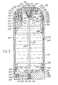
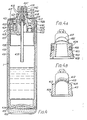
- the fluid cylinder is largely constituted by a tubular component 1 whose one open end is closed by a closure member in the form of a top plug 2.
- the tubular component 1 as shown in Figure 1 is formed by impact extrusion of an aluminium alloy such as the high-strength variety designated HE 30 by the British Standards Institution, although other metallic materials such as aluminium and copper may be impact- extruded - and stronger materials such as steel may be deep-drawn - and employed as the tubular component 1.
- an aluminium alloy such as the high-strength variety designated HE 30 by the British Standards Institution, although other metallic materials such as aluminium and copper may be impact- extruded - and stronger materials such as steel may be deep-drawn - and employed as the tubular component 1.
- Suchlike metallic materials are currently to be preferred for the tubular component, but the present invention does not exclude the alternative use of suitably strong and safe plastics materials such as, for instance, acetals, polyamides and polyesters, of appropriate wall thickness some 3 to 5 times greater than shown in Figure 1 depending particularly on the strength and creep resistance of the plastics material.
- the present invention requires that it should have an elongation before cracking or fracture of at least 7% and preferably 10% or more.
- HE 30 aluminium alloy an elongation of 12% or more is usually specified, being approximately the "42 hard" condition and obtained by partly annealing the fully heat-treated (designated HE 30TF) alloy in an oven at a temperature of 250°C for 30 minutes and by subsequent natural cooling in air at room temperature: this will lead to an ultimate tensile strength of close to 17 tons per square inch and, with a cylindrical wall thickness of 2.7 mm, the tubular component will then exhibit a burst pressure of approximately 250 bar, providing a safety factor of 4.5 in the case of carbon dioxide contained normally at a pressure in the region of 55 bar.
- the minimum 7% elongation specified permits the subsequent lip-spinning process (described later herein) to be performed satisfactorily and, in addition in the extremely unlikely event of bursting of the tubular component, ensures that it will burst by forming a ductile "buttonhole slit" in its cylindrical section and orientated longitudinally -which is a safe mode of bursting that gives rise to very little risk of flying fragments.
- the manufacturing processes used to form the tubular component e.g. impact- extrusion, deep drawing, injection moulding, etc.
- all permit the production of large batches (e.g. 1000 to 50,000 at a time) of the tubular component, which may then be e.g. heat-treated, anodised, plated, washed, etc. in bulk at low cost, obviating the need for and higher cost of undertaking such processes during subsequent cylinder assembly and avoiding all the shortcomings and disadvantages described at the beginning of this specification.
- the top plug 2 is advantageously made by injection moulding of a high-strength, low-creep engineering plastics material such as the polybutylene terephthalate variety of polyester with e.g. 45% glass reinforcement such as RYNITE (Registered Trade Mark) 545, though other plastics such as acetal, polyacetal, polyamide, other polyesters, either with or without reinforcement, may be used provided that the wall thicknesses and other critical dimensions of stressed material are adequate firstly to lead to a top plug burst pressure considerably higher than that of the tubular component at the highest service temperature envisaged and, secondly, to ensure that the creep strain of the material will not exceed some small figure such as 1.0% when the fluid cylinder pressure is held at its highest likely continuous internal pressure i.e.
- a high-strength, low-creep engineering plastics material such as the polybutylene terephthalate variety of polyester with e.g. 45% glass reinforcement such as RYNITE (Registered Trade Mark) 545
- the highest possible venting pressure of the primary pressure-relief device as described later herein for example 91 bar in this embodiment, for a very long period such as 100,000 hours, and at the highest envisaged storage temperature.
- the RYNITE 545 material of the top plug 2 will exhibit a strain of less than 1.0% after 100,000 hours at 60° if stressed to a level of 20 N/cm 2 so, using the accepted formula for a pressure vessel's hemispherical end, the wall thickness W of the notional "Buried hemisphere" indicated by the dashed line 3 in Figure 1 should be at least 5.0 mm for a buried hemisphere outside diameter of 49.0 mm in order that an internal pressure of 91 bar will produce a wall stress of no more than 20 N/mm 2 .
- the actual end wall thickness of the top plug 2 is, to scale, more than 5.0 mm, leading to a stress level much lower than 20 N/m M2 and to a creep strain of much less than 1.0% after 100,000 hours at 60°C.
- the end wall burst pressure, with an end wall thickness W of 5.0 mm, will be approximately 570 bar at 70°C for a material having an ultimate tensile strength of 126 N/mm 2 at that temperature - such as RYNITE 545 - which is much higher than the approximately 250 bar burst pressure of the tubular component 1 and which provides an ample safety factor of over 10 when employed in a carbon dioxide fluid cylinder at a normal 55 bar internal pressure.
- the only other critical dimension of stressed material in the top plug 2 of the Figure 1 embodiment is the shoulder length L, which must be sufficient to reduce the shear stress in the top plug at diameter D (measured at the root of the groove carrying the lip '0' ring 4) to a level low enough to ensure that safety criteria similar to those described heretofore for the wall thickness W in respect of burst pressure and long-term creep strain are met.
- the shear stress at diameter D (which is 49.0 mm in the Figure 1 embodiment) should be no more than 9.0 N/mm 2 to ensure that the creep strain of the shoulder 31 in shear will be less than 1.0% after 100,000 hours storage at 60°C and, assuming a fluid cylinder internal pressure of 91 bar maximum as before, this requires that the shoulder length L should be no less than 12.4 mm, as depicted in the two-thirds-scale drawing of Figure 1.
- the internal pressure causing failure of the shoulder 31 in shear at 70°C (which is chosen for this embodiment as the highest short-term temperature to which the cylinder may be exposed) will then be approximately 570 bar - for a material such as RYNITE 545 having a shear strength of 56 N/mm 2 at 70°C - which preserves the same safety factor of over 10 as for the end wall.
- the top plug 2 carries an '0' ring 5 to prevent fluid escape between it and the tubular component 1, so the lip '0' ring 4 is not essential though recommended in order to reduce the very slow escape of fluid which occurs by permeation through elastomeric materials such as nitrile elastomer which may be used for '0' rings 4, 5 and 6.
- Upstream 'O' ring 6 is provided to seal the lower extremity (as in Figure 1) of the top plug so that the narrow conduit 7 (which advantageously is a moulded helical groove similar to a male thread form providing - when bounded by the inner cylindrical surface of the tubular component 1 - a helical passageway of approximately 0.3-0.6 square millimetres of cross-sectional area for fluid flow) can be supplied with gas phase from the ullage space above the liquid surface 12, by means of the fluid offtake passage 8 which preferably is a hole moulded in the internal spine 10 which projects inward from the tapering inner surface of the top plug 2 as depicted by the dashed line 11.
- a similar crosshole 9 is provided to lead the fluid leaving the narrow conduit 7 to the orifice 13 of the primary pressure-relief device which comprises a poppet 14, advantageously moulded in a hard grade of an abrasion-resisting elastomeric material such as polyurethane elastomer and of substantially cylindrical shape and closely fitting in a cylindrical cavity 17, a compression spring 15 arranged to urge the poppet 14 against the orifice 13, a retaining plug 16 and a venting control plug 18.
- a poppet 14 advantageously moulded in a hard grade of an abrasion-resisting elastomeric material such as polyurethane elastomer and of substantially cylindrical shape and closely fitting in a cylindrical cavity 17, a compression spring 15 arranged to urge the poppet 14 against the orifice 13, a retaining plug 16 and a venting control plug 18.
- the retaining plug 16 is preferably screw-threadedly engaged in the upper (as in Figure 1) section of the cylindrical cavity 17 so that it may be screwed downwards in order to increase the force applied by the compression spring 15 downwards on the poppet 14 - and thence on the orifice 13 - until the poppet will seal the orifice at internal fluid pressures up to a certain level called the "primary venting pressure" which, in this embodiment, will be nominally 87 bar so that, when effects such as temperature expansion of the compression spring, creep and wear etc. are taken into account, the primary venting pressure will never exceed 91 bar.
- the venting control plug 18, preferably moulded in the same e.g.
- RYNITE 545 material as the top plug 2 so as to permit welding together of the two is then advantageously ultrasonically-welded or spin-welded in place to prevent undesired adjustment of the retaining plug 16 and to cause venting fluid to pass through the outlet orifice 19 to the atmosphere.
- the poppet 14 In operation of the primary pressure-relief device, as soon as the internal pressure reaches the primary venting pressure (this usually being caused by exposure to rising temperature) the poppet 14 is pushed off the orifice 13 and the contained fluid (usually gas phase from the space above the liquid surface 12 but occasionally including liquid phase whenever the gas offtake passage 8 is submerged) flows along the narrow conduit 7, the crosshole 9, through the orifice 13, around the poppet 14 and thence through the central hole seen in the retaining plug 16 in Figure 1 and finally through the outlet orifice 19.
- the contained fluid usually gas phase from the space above the liquid surface 12 but occasionally including liquid phase whenever the gas offtake passage 8 is submerged
- any liquid entering the narrow conduit is substantially or completely evaporated, which greatly reduces any risk of damage to or derangement of the primary pressure-relief device by erosion of swelling of the poppet or contraction of the compression spring.
- the pressure drop caused by the narrow conduit has another valuable effect in that, within a very few seconds after the primary pressure-relief valve operates, the fluid pressure in the orifice 13 falls and allows the poppet to be returned smartly to seal the orifice, again tending to conserve the contents of the cylinder.
- This effect is enhanced by the outlet orifice 19 which, being of a carefully-controlled size between e.g. 0.2 and 0.5 mm diameter, causes the pressure in the cavity 17 downstream of the poppet to rise during venting and to assist the compression spring to return the poppet to seal the orifice, by acting on the downstream face of the poppet in the manner of a piston.
- the poppet 14 Prior to this effect (which may take 2-10 seconds or so to act, while the flow rate of the venting fluid equilibrates), the poppet 14, being a relatively close fit in the cavity 17 (due to the presence of scratch grooves, not shown, in the wall of the cavity), will have lifted well clear of the orifice 13 owing to the additional lifting force generated by the upstream fluid- pressure acting on the "piston section" of the poppet - which is of a larger cross-sectional area than the orifice 13 - so as to allow any e.g. dirt or grit to be blown clear of the sealing faces of the poppet and orifice, thereby to prevent damage to those faces.
- This additional lifting effect may be controlled not only by the presence of scratch grooves but also by the provision of substantially- longitudinal channels or passages either in the wall of the cavity or in the exterior surface of the poppet (not shown in Figure 1 but described later herein).
- the outlet orifice 19 also controls the flow rate of venting fluid to a relatively low level, not only to conserve the cylinder's contents, but also in order that venting will be relatively quiet and gentle, so as not to cause any alarm.
- an audible warning device (as described later) can be incorporated in the pressure relief device at this point, if desired.
- the outlet orifice 19 is sized so that, during venting, the pressure in the cavity 17 downstream of the poppet 14 will rise quickly to a level above the said threshold level, causing any solid phase therein to change to liquid phase and thereby to be more easily expelled to atmosphere.
- the primary pressure-relief device achieves a very high degree of safety and reliability throughout the service life of the fluid cylinder, which may be in the region of 10-20 years.
- a secondary pressure-relief device for example, in the form of a "blow ring" 20-suitably comprising a conventional '0' ring of nitrile elastomer - mounted so as to be squeezed approximately 10-40% and to seal a first recess 21 communicating via a plurality of channels 22 with the cylinder interior against fluid flow therefrom at internal pressures up to a "secondary relief pressure", is provided.
- the first recess 21 may advantageously be an annulus which, as shown in Figure 1 tapers to an annular throat 23 which should have an annular width equal to between 0.20 and 0.50 of the uncompressed thickness of the blow ring 20 (depending upon that thickness, the chosen hardness of the blow ring and the desired secondary relief pressure).
- the annular throat is of course disposed on that side of the blow ring that is remote from the cylinder interior (i.e. the "downstream" side), and communicates with a second recess 24 having an annular width greater than the uncompressed thickness of the blow ring (so as not to be sealed by the blow ring) and communicating by a plurality of holes 25 with the cylinder exterior.
- the secondary pressure-relief device is designed to operate at a secondary relief pressure of 108 bar nominally (and never of greater than 124 bar under the effect of manufacturing tolerances and varying hardnesses of the blow ring) and then to vent all of the cylinder's contents in a relatively noisy manner so as to attract attention.
- the blow ring will not reseal automatically and the cylinder must be returned for examination of the reasons for apparent failure of the primary pressure-relief device and for any rectification thereof, before the cylinder may be refilled and returned to service.
- the blow ring is much less prone to interference and thereby provides a dependable back-up to the primary pressure-relief device, ensuring that the internal pressure will never exceed 124 bar in service and thereby maintaining a safety factor of at least 1.6 - even in the rare and extreme circumstances described.
- the features of this type of secondary pressure-relief device may be seen more clearly in the embodiment of Figure 3, described later herein.
- the secondary pressure-relief device is incorporated around the valve assembly 26.
- the secondary pressure relief device may be located elsewhere in the top plug or closure member, in which case the longitudinal axis thereof should, advantageously, lie substantially parallel to the longitudinal axis of the container.
- the valve assembly being of known type, will not be described in detail herein, apart from disclosing the actuating rod 27 which extends through the outlet passage 28 and which, when pressed downwards (as in Figure 1), allows fluid to flow from the interior and out through the outlet passage 28.
- the upper end of the top plug (as in Figure 1) is formed to incorporate an integral male thread 29 (which distinguishes the present invention from known types of gas cylinder having a separate - usually male-threaded - metallic coupling normally welded, brazed or soldered to a metallic cylinder having a neck reduction) which allows the whole cylinder to be screwed into the appliance or other device to be supplied with fluid, normally in such a manner that the actuating rod 27 is depressed so as to allow fluid flow to the appliance or other device.
- an integral male thread 29 which distinguishes the present invention from known types of gas cylinder having a separate - usually male-threaded - metallic coupling normally welded, brazed or soldered to a metallic cylinder having a neck reduction
- a coupling 'O' ring 30, advantageously of nitrile elastomer containing molybdenum disulphide or other lubricant, is provided as shown in order to seal the coupling of the whole cylinder to certain types of appliance or device such as the charging head shown in Figure 2, being specifically an 'O' ring in radial compression so as to seal before the male thread is screwed fully home and the actuating rod is depressed, so as to prevent fluid escape during this coupling process.
- the top plug 2 is provided with an integral circumferential shoulder 31 having a diameter advantageously between 0.2% and 1.0% greater than the internal diameter of the tubular component 1, so as to provide an interference fit between the two when the tubular component is assembled axially onto the top plug.
- a similar or slightly lesser amount of interference is provided over that section of the top plug which comprises the major diameter of the male thread form providing the helical passageway of the narrow conduit 7, so that the said major diameter will be pressed firmly against the bounding inner cylindrical wall surface of the tubular component in order substantially to prevent axial fluid flow therebetween and to constrain the fluid to flow helically along the narrow conduit.
- a retaining groove 32 having a diameter approximately 7% less than that of the circumferential shoulder (in the case of using HE 30 aluminium alloy for the tubular component, and generally in the range of 5-10% less in the case of other materials used for the tubular component) and into which the upper extremity (as in Figure 1) of the tubular component is firmly deformed, advantageously crimping, swaging or by rotating the cylinder about its central axis whilst it is firmly supported in e.g.
- a lathe and by applying a "spinning tool” having a rolling head to roll on and press the upper extremity of the tubular component radially inwards, so as to form a cold-spun lip 33 gripping the retaining groove "core" 32.
- a cold-spun lip as just described may be adequate for fluid cylinders containing fluids at pressure up to e.g. bar (especially where such cylinders are of diameter less than e.g. 30 mm, in which case pressures up to even 200 bar may be safely contained by a cold-spun lip as just described), the embodiment of Figure 1 achieves a much greater degree of safety by employing a retaining band 34, which may be of one of a variety of materials including plastics, cast aluminium or zinc alloy or other metallic material, forged or extruded or machined metallic material, etc.
- the retaining band may be fitted in place by firstly stretching it elastically using e.g. a tool similar to those of known type which are used to stretch and fit '0' rings etc., so that it will slide over the cold-spun lip.
- Another technique, in the case of a metallic retaining band especially, is the use of preheating to expand the retaining band, allowing it to be slid into place whereupon it will cool and contract firmly onto the cold-spun lip.
- the retaining band should embrace substantially or nearly all of the extent of the cold-spun lip and also should be fitted with its downward edge (as in Figure 1) closely adjacent to the circumferential shoulder 31 so as to minimise any incipient tendency of the cold-spun lip to be withdrawn downwards (as in Figure 1) over the circumferential shoulder by the withdrawal force generated on the tubular component 1 by the internal fluid cylinder pressure.
- a retaining band of the type so far described may have a plain cylindrical inside surface (as illustrated later herein, in the Figure 3 embodiment) or, advantageously, its inside surface may be roughened or slightly tapered outwards in a downward direction (as in Figure 1), so as to cause it to grip the cold-spun lip more firmly.
- Suchlike retaining bands will usually be adequate to hold the tubular component firmly in place against internal pressures up to between 200 and 500 bar, depending upon the diameter, material and wall thickness of the tubular component.
- the Figure 1 embodiment is intended for extremely high safety, to which end the retaining band 34 incorporates a circumferential ridge 35 on its inside surface and advantageously having a cross-section in the shape of a saw-tooth orientated as shown in Figure 1 so that the circumferential ridge 35 acts as a barb to prevent any incipient tendency of the cold-spun lip to expand and withdraw over the circumferential shoulder 31, by means of the engagement of the circumferential ridge 35 with a circumferential groove (also having reference numeral 35 in Figure 1) in the outside surface of the cold-spun lip and having a cross-section substantially matching that of the circumferential ridge 35.
- a circumferential groove also having reference numeral 35 in Figure 1
- Such a circumferential groove may of necessity cause a local thinning of the cold-spun lip but the cold-spun lip is on that side of the lip 'O' ring 4 that is remote from the cylinder interior so, even if 'O' ring 5 fails to seal, the cold-spun lip does not have to resist any internal fluid pressure in the manner of the remainder of the cylindrical section of the tubular component 1 which has to resist both a longitudinal stress of a level proportional to the internal fluid pressure and a hoop stress equal to twice that level.
- the circumferential groove may have a depth equal to e.g.
- fluid cylinders of this type of construction invariably fail at a sufficiently high internal pressure owing to the hoop stress in the main cylindrical section of the tubular component reaching a level high enough to cause bursting in the shape of a safe "buttonhole slit", with little or no accompanying damage to or deformation of the cold-spun lip or of its retaining band.
- a tubular component may be employed in which that part which is deformed to provide a lip has a wall which is greater in thickness and thereby stronger than the remaining cylinder wall of the component.
- the lip portion may have a wall thickness up to 80% greater than that of the body portion of the component, which thickness may extend for up to 5 to 10% of the length of the component.
- a retaining band can also be used with a tubular component having a thickened lip.
- a nozzle member 201 (containing a known type of dispensing valve) advantageously injection-moulded in a high-strength plastics material such as acetal, polyacetal, polyester or a grade of polyamide known as "Supertough ZYTEL" (Registered Trade Mark) Grade ST 801 with an integrally-moulded flared portion or shroud 202 which, when the charging head is screw-threadedly engaged by means of its integrally-moulded female thread 203 engaging with the male thread 29 of the top plug 2 of the fluid cylinder shown in Figure 1, conforms closely to the top side of the top plug (as in Figure 1) so as to present a neat appearance, is provided with an integrally-moulded sealing surface 204 to embrace the coupling 'O' ring 30 of Figure 1 and to compress it radially by approximately 20% so as to seal the charging head to the top plug.
- a high-strength plastics material such as acetal, polyacetal, polyester or a grade of poly
- This embracing of the coupling '0' ring 30 by the sealing surface 204 occurs during screw-engagement of the charging head to the top plug approximately 1-2 turns before the actuating probe 205 shown in Figure 2 comes into contact with the actuating rod shown in Figure 1, and the final screwing-down (as in Figures 1 and 2) of the charging head causes the actuating probe 205 to depress the actuating rod 27 and to admit fluid from the fluid cylinder to the interior of the charging head.
- the actuating probe 205 is provided with a central hole and a cross-slotted tip 206 as shown in Figure 2 to permit flow of fluid onwards to the dispensing passage 207.
- the combined assembly of the charging head of Figure 2 and the fluid cylinder of Figure 1 may, when the latter contains a liquefied gas, be inverted so that the charging head may then dispense liquefied gas, instead of dispensing gas phase when in the upright position shown in Figures 1 and 2.
- the shroud 202 impedes access or tampering with the primary pressure relief device and the blow-ring, and ensures that fluid venting therefrom is guided to atmosphere by the shroud in a multi-directional fashion, thereby substantially eliminating any jet reaction which might otherwise cause the fluid .cylinder to move about in a violent and possibly dangerous manner.
- the charging head or shroud of Figure 2 is only one example of several alternative adaptor assemblies incorporating the features disclosed and which may be used to couple the fluid cylinder of Figure 1 to any of a variety of appliances such as fire extinguishers, medical equipments such as anaesthetic and oxygen dispensers, appliances operated by compressed or vapourised gases, and various welding and industrial equipment.
- appliances such as fire extinguishers, medical equipments such as anaesthetic and oxygen dispensers, appliances operated by compressed or vapourised gases, and various welding and industrial equipment.
- a standard cylinder design such as in Figure 1 may satisfy a large number of uses and the said adaptor assemblies may easily be detached, lightening the cylinder to save transportation costs when it is returned for refilling.
- the fluid container illustrated in Figure 4 is similar to that shown in Figure 1 and as described above, and identical or substantially identical features are referred to by the same reference numerals. However, as is readily apparent, there are also significant differences between the two containers and these are described below in detail.
- a secondary pressure relief device is present in the container of Figure 4 in the form of at least one bursting disc shown generally as 401.
- the actual disc may be metallic or of a plastics material and assemblies incorporating examples of such discs are illustrated respectively in Figures 4a and 4b.
- the disc assembly 401 corresponds to the enlarged assembly shown in Figure 4a and takes the form of a part hemispherical thin metal disc 402, usually of copper, nickel or brass, which is shaped over a cylindrical metal or plastics retaining plug 403.
- the disc is formed with a skirt portion 404 which extends over the substantially cylindrical surface 405 of the retaining plug for a distance portion equal to at least 20% of the diameter of the disc.
- An '0' ring 406 provides additional circumferential sealing means to ensure that fluid does not escape from the container via the base of the skirt portion.
- the broken lines 407 show the form of the disc when under excess fluid pressure and immediately prior to bursting.
- FIG. 4b An alternative bursting disc assembly is shown in Figure 4b in which the thin part-hemispherical disc 410 and its retaining plug 411 are integrally formed (e.g. by precision injection molding) from the same plastics material.
- the plastic material is the same as that comprising the top plug or closure member 2, when the disc assembly may be conveniently ultrasonically-welded to its housing at 408.
- the broken lines 412 show the form of the disc when under excess fluid pressure and immediately prior to bursting.
- the integral retaining plug 411 has a circumferential shoulder 413 which abuts and is thereby retained by the stepped bore 439; this mimics the main circumferential shoulder 440 of the top plug or closure member and the lip portion 426 that retains the top plug or closure member and causes the bursting disc assembly to experience the same stress patterns as in the top plug or closure member, further increasing safety.
- both types of secondary pressure relief devices may be present in fluid containers according to the present invention, designed or "set” to burst at different fluid pressures.
- the three pressure relief devices may be housed symmetrically (at 120° spacing) around the upper end of the interior of the top plug or closure member.
- Fluid venting to atmosphere from any of the relief devices contacts the base portion 415 of a shroud indicated generally as 416 which has the effect of spreading the fluid around the top of the top plug, within the gap between the plug and the shroud, thus equalizing the pressure of the fluid, so that on escaping from the shroud via a series of holes 417 symmetrically arranged around the circumference of the shroud, the risk of fluid having a net jet reaction effect upon the container causing it to move about in a possibly dangerous fashion is reduced to a minimum.
- the shroud 416 and the top plug or closure member comprise similar materials e.g. polyesters, of relatively high tensile strength but low elongation and impact strength for the top plug or closure member: and of relatively low tensile strength but high elongation and impact strength for the shroud, in order that the shroud may protect the top plug or closure member against shocks and impacts, so that the two parts may be welded together (by known ultrasonic or spin-welding methods) either at a series of points 418 or to form a continuous annulus to provide a frangible connection.
- similar materials e.g. polyesters, of relatively high tensile strength but low elongation and impact strength for the top plug or closure member: and of relatively low tensile strength but high elongation and impact strength for the shroud, in order that the shroud may protect the top plug or closure member against shocks and impacts, so that the two parts may be welded together (by known ultrasonic or spin-welding methods) either at a
- Such a safety measure allows the shroud 416 to break away from the top plug if subjected to undue stress arising, for example, from the presence of an attached appliance, thus minimizing the risk of the stress being transmitted to and damaging the upper extremity of the top plug and so maintaining the pressure integrity of the container.
- Parts 419 on the shroud represent means for attaching suitable appliances and may conveniently take the form of a threaded section or threaded sleeve.
- a hollow annulus 441 extends within the upper portion of the shroud 416, so as to provide a frangible neck 442 of a relatively thin wall and of low strength so that part 443 may break away safely in the event of excessive loading being applied to the fluid container when installed in an appliance.
- an audible alarm device comprising a flexible sound emitting diaphragm 421 mounted between the cup 422 and plug 423 may be conveniently incorporated downstream of the bleed poppet cylinder 424.
- the tubular component 1 has a lip portion 426 with a greater wall thickness than that of the remainder of the component. Lip portions extending up to 10% of the length of the tubular component and up to 150% greater in thickness than the body portion of the component have been exploited.
- a coaxial cylindrical jacket or sleeve 430 comprising, for example, an impact extruded aluminium alloy provides a container for a heat storage substance 431 in contact with the wall of the tubular component 1.
- the high thermal conductivity of the alloy also permits an easy inflow of heat to the heat storage substance.
- the base 432 of the jacket is flat to allow for freestanding, which shape is also easier to impact extrude than a concave end or convex hemispherical end.
- a centralising ring 433 of a suitable plastics material, having slots 434 to allow for the movement of the heat storage substance, is also provided.
- a gas off-take tube 435 extending to the vicinity of the centre of volume of the container ensures gas only off-take when the container is up to half full of liquid. This arrangement permits the operation of the container when in any attitude.
- a heat storage substance enables the fluid container of the present invention to be exploited as a "power capsule".
- An alternative form of such a capsule designed to maximise the benefit of the heat storage substance provides a gas off-take tube from the orifice 436 with a channel connecting the opening 437 to an extended valve plug 438.
- the cavity created by this extension of the valve plug may be filled with a metal foam, mesh or sintered or porous metal to minimise the collection and retention in the cavity of liquefied gas.
- one of the two secondary pressure relief devices may be replaced by a non-return filling valve of known design (e.g. a steel ball in a tapered tube) to allow for rapid direct filling of the fluid container.
- a tubular component 301 which, in this embodiment, is a length of thin-walled pipe (which may be a metal, metallic alloy or which may comprise metallic strip wound and embedded in a plastics material such as epoxy resin or other thermosetting or thermoplastic material as in the known DUNLOPIPE (Registered Trade Mark) so as to be corrosion-resisting) having two open ends which are closed by a top plug 302 and an end plug 303 which in this embodiment comprise aluminium diecastings and which are tightly-fitting into the tubular component 301 and sealed thereto firstly by the plug 'O' rings 304 and 305 and, secondly for additional leak-tightness, by the lip '0' rings 306 and 307.
- the tubular component in this embodiment (which is intended for containing liquefied carbon dioxide or the like in terms of pressure) has a burst strength of approximately 300 bar, and the top and end plugs have
- the top plug 302 is provided with an upstream 'O' ring 308 to bound a plurality of narrow conduits 309 formed in the outer cylindrical surface of the top plug in the form of several substantially- longitudinal channels bounded by the inner cylindrical surface of the tubular component 301 and having a total cross-sectional area for fluid flow of between approximately 2 and 5 square millimetres communicating between a fluid offtake passage 310 (which is angled as shown to communicate with the ullage space above the liquid surface (as in Figure 3) 311) and a crosshole 312 so as to cause a pressure drop in the range 5 to 50 bar when the primary pressure-relief device operates.
- a fluid offtake passage 310 which is angled as shown to communicate with the ullage space above the liquid surface (as in Figure 3) 311
- a crosshole 312 so as to cause a pressure drop in the range 5 to 50 bar when the primary pressure-relief device operates.
- the primary pressure-relief device comprises an orifice 313 which communicates with the crosshole 312 and which is normally sealed by a poppet 314 pressed downwards (as in Figure 3) by a compression spring 315 which is enclosed and guided slidably (as also is the poppet 314) by the substantially-cylindrical cavity 317.
- a retaining plug 316 having a hole 320 for fluid escape is advantageously screw-threadedly engaged in the upper (as in Figure 3) extension of the cylindrical cavity 317 for adjustment of the compression spring force bearing down on the poppet so that the poppet will seal the orifice against internal fluid pressures up to 100 bar approximately, above which "primary venting pressure" the poppet will lift off the orifice and allow fluid to vent from the interior.
- the poppet 314 (which in this embodiment may advantageously be injection-moulded in "Supertough" ZYTEL (Registered Trade Mark) Grade ST 801 or in HYTREL (Registered Trade Mark) semi- elastomer) is formed with a piston section 321 which is closely-fitting in the cylindrical cavity 317 (subject to the presence of one or more scratch grooves in the wall of the cavity) and which is of approximately three times the diameter of the bottom (as in Figure 3) face of the poppet where it seals the orifice 313.
- "Supertough" ZYTEL Registered Trade Mark
- HYTREL Registered Trade Mark
- Passages 322 for fluid flow may advantageously be moulded in the outer cylindrical surface of the piston section 321 of the poppet (or in the adjacent cylindrical wall) to provide escape channels substantially parallel with the central axis of the poppet for the escape of such solid particles and also to reduce and thereby regulate the extent of the additional poppet lift afforded by the piston section.
- a venting control plug 318 is securely fixed (to prevent tampering with or accidental adjustment of the retaining plug 316) in the upper (as in Figure 3) extremity of the cylindrical cavity 317 and provided with one or more outlet orifices 319 of total cross-sectional area for fluid flow carefully controlled so that, when the poppet is lifted off the orifice 313 by internal cylinder pressure, the fluid pressure in the cylindrical cavity 317 immediately above it (as in Figure 3) will quickly rise above a threshold pressure above which no solid phase deriving from the fluid can exist (i.e.
- the narrow conduit(s) 309 cause, via their stated pressure drop effect on the venting fluid, substantially all of any liquid phase flowing through them to be evaporated so that little if any liquid phase will enter the primary pressure-relief device and either change (transiently) to solid phase or otherwise harm the operation of the primary pressure-relief device by causing e.g. swelling of the poppet or temperature effects on the spring rate of the compression spring.
- any such evaporation of any liquid phase (and the expansion of any subsequent vapour and of the accompanying gas phase from the ullage space above the liquid surface 311) promoted by the stated pressure drop along the narrow conduits 309 will cause the fluid flowing therein to fall in temperature and, by virtue of the heat-exchange relationship between the narrow conduit(s) and the tubular component 301, to chill the tubular component 301.
- This chilling effect will be conducted to the contents of the cylinder, lowering their temperature and pressure slightly (or tending to prevent any rise in those values) and so tending to conserve the contents of the cylinder.
- the outlet orifice 319 also controls the flow rate of venting fluid to a relatively low level, in order to conserve fluid during the short period during which the fluid pressure in the cylindrical cavity 317 builds up and causes the poppet to return smartly to seal the orifice 313 (this smart return action being further enhanced by the fall in pressure at the orifice in consequence of the pressure drop along the narrow conduit(s)), and also in order that such venting will be gentle and quiet.
- a secondary pressure-relief device comprising a blow ring 323, advantageously being a conventional '0' ring moulded in nitrile elastomer with a small addition of molybdenum disulphide or other lubricant so as to ensure its consistent operation as a pressure-relief device, a first recess 324 of generally annular form with an annular width approximately equal to 80% of the thickness of the uncompressed blow ring 323 and tapering down to a throat 325 of annular form (in this embodiment) and width equal to approximately 30 to 40% of the thickness of the uncompressed blow ring and against which the blow ring may be urged by fluid pressure from the cylinder interior communicating with the first recess 324 through a plurality of channels 326, and a second recess 327 of generally annular form (in this embodiment) with an annular width greater than the thickness of the uncompressed blow ring so as not to be sealed by the blow
- a third safety device in the form of a conventional bursting disc 330 advantageously made of aluminium or copper or one of their alloys such as brass and secured in a gas-tight manner in the top plug by a hollow plug 331 screw-threadedly engaged with a female thread in the top plug, is provided so as to burst if the internal pressure rises to approximately 175 bar and in order then to vent all the cylinder's contents to atmosphere.
- a top retaining groove 332 is provided with a diameter approximately 5% less than the inside diameter of the tubular component and into which the upper (as in Figure 3) extremity of the tubular component is spun or otherwise deformed so as to form a cold-spun lip 333 which is then grippingly retained by a top retaining band 334 formed as shown in Figure 3 from advantageously, diecast aluminium or injection-moulded high-strength plastics material such as e.g.
- RYNITE 545 (Registered Trade Mark) and assembled by prior elastic stretching or prior heat-expansion followed by relaxation or cooling so as to grip the cold-spun lip over its whole length and, in particular, at that part of the cold-spun lip closely adjacent to the circumferential shoulder 335 provided on the top plug 302.
- the lower (as in Figure 3) extremity of the tubular component 301 is similarly spun or otherwise deformed firmly into a retaining groove 336 in the end plug 303 so as to form a lower cold-spun lip 337 which, according to another preferred method of the present invention, is held firmly in place by a gap-filling adhesive such as PLASTIC PADDING (Registered Trade Mark) or DEVCON (Registered Trade Mark) or similar hard- setting adhesives based on epoxy or polyester or polyurethane or suchlike compounds which is applied on the outer circumference of the cold-spun lip 337 so as substantially to fill the cavity 338 between the cold-spun lip 337 and the inner cylindrical surface of a lower retaining band 339 which has a diameter significantly larger than that of the cold-spun lip's 337's exterior surface and, in this embodiment, substantially equal to the outer diameter of the tubular component 301 so as to grip it in the region of the lower circumferential shoulder 340.
- a gap-filling adhesive such as PLASTIC P
- This method of retaining the cold-spun lip 337 avoids the need to stretch or heat- expand the lower retaining band 339 prior to fitment or to provide the engaging circumferential ridge and groove of the embodiment shown in Figure 1, and naturally causes the outer surface of the lower retaining band 339 to be proud of the outer surface of the tubular component, enabling it to support another feature of the present invention described as follows.
- An outer sleeve 341 of thin seamed metal sheet or plastics material or the like may, in many applications of the present invention wherein it is desired to withdraw fluid from the cylinder at a high rate or for a protracted period as for instance in the case of its use as a fire extinguisher, be fitted substantially co-axial with the tubular component and supported by the outer surfaces of the lower retaining band 339 and the top retaining band 334, being prevented from downward (as in Figure 3) movement relative to the end plug by a ledge 342 thereon and being sealed against leakage by an upper seal 343 and a lower seal 344, and the annular space between the tubular component and the outer sleeve partly or substantially filled with a heat storage substance 345.
- the action of the heat storage substance 345 is to prevent excessive chilling of the cylinder and its contents - and the excessive fall in internal pressure that would occur in consequence and cause an excessive reduction in the flow rate of withdrawn fluid - by releasing heat to the tubular component.
- the heat released may be the sensible heat of the heat storage substance 345 which in that case should advantageously be a liquid or solid substance of high specific heat such as water or paraffin oil or paraffin wax or lithium metal; or the heat released may be the latent heat of fusion as a liquid charges (i.e.
- liquid suitable for such release of latent heat include, in the case of a fluid cylinder supplying carbon dioxide gas for fire-extinguishing purposes, those having a freezing point between approximately -20°C (at which temperature the vapour pressure of carbon dioxide is 19.7 bar) and approximately +20°C (above which temperature the heat storage substance may not be remelted by heat from the ambient surroundings) are generally to be preferred, and include such substances as water (freezing point 0°C), polyethylene glycols having various freezing points between
- the heat storage substance 345 may be such as to release latent heat of hydration or solution or crystallisation at a certain falling temperature between +20°C and -20°C (for example), such as para-xylene which forms large nodular crystals and releases both latent heat and heat of crystallisation at falling temperatures in the band of +10°C to +8°C approximately.
- Such heat storage substances may be filled into the annular space between the tubular component and the outer sleeve 341 to a high level 346 leaving a little free ullage space above it as shown in Figure 3 to allow for expansion effects, or to a lower level 347 below the upstream 'O' ring 308 so that the chilling effect caused by the narrow conduit(s) 309 may still be conducted by the tubular component 301 to the liquid contents (when their surface level is above the lower level 347; if the liquid surface 311 falls below the level of the upstream '0' ring 308 approximately-and certainly if it falls below the lower level 347 - the chilling effect as aforesaid is no longer needed because the ullage space above the liquid surface is sufficient to prevent any substantial rise in internal pressure and, therefore, to prevent venting of the contents through the primary pressure-relief device) without any impediment by the heat storage substance which would otherwise tend to annul the chilling effect.
- a fluid cylinder containing approximately 3 kilogrammes of largely-liquid carbon dioxide as in the Figure 3 embodiment and used as a fire extinguisher may, by virtue of the heat storage substance 345 and relating features of the present invention, be used to fight a fire continuously and for a protracted period until the contents are substantially exhausted, providing approximately 2000 litres of carbon dioxide gas - sufficient to exclude air from the volume of a small kitchen or garage to an extent sufficient to extinguish e.g. a large cooking-fat fire or a blazing car engine compartment.
- the heat storage substance and relating features only some 500 to 1000 litres of gaseous carbon dioxide may be supplied before the internal cylinder pressure falls to a level insufficient to propel an adequate gas stream at a fire.
- a lower valve 348 of known type normally closes a drain orifice 349 in a gas-tight manner, being normally urged upwards (as in Figure 3) by means of the push-rod 350 connecting it to a plunger 351 guided sealingly through a co-axial bore 364 in the threaded member 329 provided with a rod seal 352 of known type.
- the lower (as in Figure 3) end of the plunger 351 incorporates an upper valve 353 of known type so as to provide a second gas-tight seal (the first being the rod seal 352) against fluid escape during the majority of service when the fluid cylinder is not being used to dispense its contents.
- the sealing diameter of the upper valve 353 is larger than that of the lower valve 348 in order that the internal fluid pressure causes a net upward force on the lower valve so as to keep it and the upper valve normally closed as shown in Figure 3.
- the plunger 351 is secured to a button 354 which, when depressed by hand or other means, opens the lower valve 348 and thus the drain orifice 349 whilst also opening the upper valve 353 so as to annul the upward (as in Figure 3) force exerted on it by the internal fluid pressure and thereby diminish the necessary force to keep the button 354 depressed during dispensing - which might otherwise become excessive and tiring.
- a smaller and tolerable upward return force is provided by the internal fluid force acting on the plunger at the sealing diameter of the rod seal 352, this diameter being approximately 3 to 4.5 mm (i.e.
- the drain orifice 349 communicates with a discharge passage 355 which may conveniently lead dispensed fluid through a filter 356 held in place by a screw-threaded nipple 357 engaging a female thread provided in the end plug 303.
- a gas-tight sealed access plug 358 is preferable fitted by screw-threaded engagement co-axial with the end plug and under (as in Figure 3) the lower valve, and a female-threaded socket 359 having a thread size and form matching that of the male thread 29 in the top plug 2 of the fluid cylinder illustrated in the Figure 1 embodiment and having a sealing surface 360 such as the sealing surface 204 of the charging head illustrated in Figure 2, is provided in the end plug co- axial with the nipple 357.
- a fluid cylinder such as that depicted in the Figure 1 embodiment may be screwed and sealed into the socket 359 (so that the nipple 357, which is hollow and has a cross-slotted tip for fluid flow, depresses the actuating rod 27 and opens the valve assembly 26 of the Figure 1 fluid cylinder) and, when the button 354 is depressed, liquid carbon dioxide (for example) may flow into the Figure 1 fluid cylinder so as to refill it for further use.
- gaseous carbon dioxide may be dispensed into e.g. a Figure 1 fluid cylinder or into the atmosphere by inverting the Figure 3 fluid cylinder and pressing the button 354.
- a tubular stand-pipe 361 may be fitted tightly in the well 362 wherein it is sealed by the well-seal 363 and whereby it is supported substantially co-axial with the push-rod 350, the upper (as in Figure 3) extremity of the stand-pipe 361 opening into the ullage space above the liquid surface 311, from whence gas rather than liquid may be dispensed downwards through the stand-pipe 361 and the drain orifice 349.
Landscapes
- Engineering & Computer Science (AREA)
- Mechanical Engineering (AREA)
- General Engineering & Computer Science (AREA)
- Health & Medical Sciences (AREA)
- Public Health (AREA)
- Business, Economics & Management (AREA)
- Emergency Management (AREA)
- Filling Or Discharging Of Gas Storage Vessels (AREA)
- Safety Valves (AREA)
- Containers And Packaging Bodies Having A Special Means To Remove Contents (AREA)
Claims (48)
Priority Applications (1)
| Application Number | Priority Date | Filing Date | Title |
|---|---|---|---|
| AT82900979T ATE28102T1 (de) | 1981-04-06 | 1982-04-05 | Fluessigkeitsbehaelter. |
Applications Claiming Priority (2)
| Application Number | Priority Date | Filing Date | Title |
|---|---|---|---|
| GB8110733 | 1981-04-06 | ||
| GB8110733 | 1981-04-06 |
Related Child Applications (2)
| Application Number | Title | Priority Date | Filing Date |
|---|---|---|---|
| EP19870100047 Division EP0231745A3 (fr) | 1981-04-06 | 1982-04-05 | Dispositif de sécurité |
| EP87100047.7 Division-Into | 1987-01-04 |
Publications (2)
| Publication Number | Publication Date |
|---|---|
| EP0075572A1 EP0075572A1 (fr) | 1983-04-06 |
| EP0075572B1 true EP0075572B1 (fr) | 1987-07-01 |
Family
ID=10520971
Family Applications (2)
| Application Number | Title | Priority Date | Filing Date |
|---|---|---|---|
| EP19870100047 Ceased EP0231745A3 (fr) | 1981-04-06 | 1982-04-05 | Dispositif de sécurité |
| EP19820900979 Expired EP0075572B1 (fr) | 1981-04-06 | 1982-04-05 | Conteneurs de fluides |
Family Applications Before (1)
| Application Number | Title | Priority Date | Filing Date |
|---|---|---|---|
| EP19870100047 Ceased EP0231745A3 (fr) | 1981-04-06 | 1982-04-05 | Dispositif de sécurité |
Country Status (10)
| Country | Link |
|---|---|
| US (1) | US4854343A (fr) |
| EP (2) | EP0231745A3 (fr) |
| JP (1) | JPH0650160B2 (fr) |
| KR (1) | KR890002990B1 (fr) |
| AU (1) | AU8277982A (fr) |
| DE (1) | DE3276668D1 (fr) |
| IN (1) | IN158417B (fr) |
| IT (1) | IT1150786B (fr) |
| WO (1) | WO1982003441A1 (fr) |
| ZA (1) | ZA822328B (fr) |
Families Citing this family (45)
| Publication number | Priority date | Publication date | Assignee | Title |
|---|---|---|---|---|
| DE3708835C1 (de) * | 1987-03-18 | 1988-06-01 | Total Feuerschutz Gmbh | Feuerloescher |
| WO1992010702A1 (fr) * | 1990-12-10 | 1992-06-25 | Abbott, Martin, John, Blaney +Lm | Recipient pour fluide |
| DE19618452B4 (de) * | 1996-05-08 | 2005-05-12 | Robert Bosch Gmbh | Aggregat zum Fördern von Kraftstoff aus einem Vorratstank zu einer Brennkraftmaschine |
| US5779089A (en) * | 1996-07-26 | 1998-07-14 | Forma Scientific, Inc. | Cryogenic storage apparatus with lid vent |
| FR2786413B1 (fr) * | 1998-12-01 | 2001-11-09 | Oreal | Ensemble de distribution d'une composition multi-phase, utilisation d'un tel ensemble et procede d'utilisation |
| US6499646B1 (en) * | 2000-04-05 | 2002-12-31 | Indian Sugar And General Engineering Corp. | Fusion welded liquefiable gas cylinder with overpressure protection heads and method for making the same |
| JP2003056782A (ja) * | 2001-08-09 | 2003-02-26 | Nissan Motor Co Ltd | 樹脂製コネクタと樹脂製チューブの接続構造 |
| DE10138290B4 (de) * | 2001-08-10 | 2006-07-27 | Air Liquide Deutschland Gmbh | Kaltgasgerät mit vereisungsfreier Düse |
| KR100589450B1 (ko) * | 2003-01-24 | 2006-06-14 | 가부시키가이샤 도요다 지도숏키 | 고압탱크 |
| WO2006026842A1 (fr) * | 2004-08-23 | 2006-03-16 | Delgado Junior Augusto De Jesu | Extincteur fabrique a partir de polymere |
| DE102004041448B3 (de) * | 2004-08-27 | 2005-11-17 | Dräger Medical AG & Co. KGaA | Druckbeständiger Flüssigkeitstank |
| DE102005010282B3 (de) * | 2005-03-07 | 2006-11-02 | Rothenberger Ag | Druckgasquelle mit Brenngasfüllung |
| DE102005010281B3 (de) * | 2005-03-07 | 2006-10-05 | Rothenberger Ag | Druckgasquelle mit Brenngasfüllung |
| GB0516560D0 (en) * | 2005-08-12 | 2005-09-21 | Carr Roger | Fire extinguisher head cap with modified valve |
| US10149935B2 (en) * | 2006-11-27 | 2018-12-11 | Frank Levy | Delivery system and method for the effective and reliable delivery of controlled amounts of a medical fluid |
| US11712510B2 (en) | 2006-11-27 | 2023-08-01 | Frank Levy | Delivery system and method for the effective, reliable and foolproof delivery of controlled amounts of a medical fluid |
| US20180087718A1 (en) * | 2006-11-27 | 2018-03-29 | Frank Levy | Disposable single-use cartridge for holding compressed medical gas |
| US9651197B2 (en) * | 2006-11-27 | 2017-05-16 | Frank Levy | Disposable cartridge for holding compressed medical gas |
| BRPI0702725B1 (pt) * | 2007-03-29 | 2018-05-08 | Augusto De Jesus Delgado Junior | extintor de incêndio com recipiente plástico descartável |
| ITMI20080441A1 (it) * | 2008-03-17 | 2009-09-18 | O D L Srl | Gasatore per acqua con fondelli in plastica |
| JPWO2010044298A1 (ja) * | 2008-10-16 | 2012-03-15 | 株式会社初田製作所 | 消火器、消火剤貯蔵容器、及び消火剤貯蔵容器のプリフォーム |
| US8091203B2 (en) * | 2008-11-21 | 2012-01-10 | GM Global Technology Operations LLC | High pressure tank and method thereof |
| USD658763S1 (en) | 2010-02-02 | 2012-05-01 | 3M Innovative Properties Company | Dental capsule |
| ITCO20110011A1 (it) * | 2011-03-22 | 2012-09-23 | Nuovo Pignone Spa | Recipiente di un apparato di accumulo e rilascio di calore, assieme per accumulo e rilascio di calore, e impianto di produzione di energia |
| US9192798B2 (en) | 2011-10-25 | 2015-11-24 | Kidde Technologies, Inc. | Automatic fire extinguishing system with gaseous and dry powder fire suppression agents |
| US9463341B2 (en) | 2011-10-25 | 2016-10-11 | Kidde Technologies, Inc. | N2/CO2 fire extinguishing system propellant gas mixture |
| US9308406B2 (en) | 2011-10-25 | 2016-04-12 | Kidde Technologies, Inc. | Automatic fire extinguishing system having outlet dimensions sized relative to propellant gas pressure |
| US9302128B2 (en) | 2011-10-25 | 2016-04-05 | Kidde Technologies, Inc. | Automatic fire extinguishing system with internal dip tube |
| WO2013133799A1 (fr) * | 2012-03-06 | 2013-09-12 | International Engine Intellectual Property Company, Llc | Réservoir d'ammoniac embouti à compactage élevé |
| WO2013133801A2 (fr) * | 2012-03-06 | 2013-09-12 | International Engine Intellectual Property Company, Llc | Cartouche d'ammoniac multicouche (à double paroi) |
| US8985561B2 (en) | 2012-06-29 | 2015-03-24 | Bonne O Inc. | Beverage carbonating system and method for carbonating a beverage |
| US9198455B2 (en) | 2012-06-29 | 2015-12-01 | Bonne O Inc. | Carbon dioxide source tablet and beverage carbonating system including the same |
| USD731223S1 (en) | 2013-10-11 | 2015-06-09 | Bonne O Inc. | Beverage carbonation system base |
| FR3017442B1 (fr) * | 2014-02-13 | 2016-07-29 | Air Liquide | Reservoir composite de gaz sous pression et procede de remplissage |
| US10112454B2 (en) * | 2014-11-24 | 2018-10-30 | Continental Automotive Systems, Inc. | Closing cover with integrated pressure retention valve housing for air spring applications |
| CN105290736B (zh) * | 2015-11-20 | 2018-05-04 | 沈阳航天新光集团有限公司 | 高压气瓶前封头封口的加工方法 |
| KR101665540B1 (ko) * | 2016-03-28 | 2016-10-14 | 오제이씨(주) | 가스용기의 안전밸브 |
| KR101693199B1 (ko) | 2016-06-13 | 2017-01-06 | 한국해양과학기술원 | 티타늄 밴드를 포함하는 유리구 내압 용기 |
| EP3299082A1 (fr) | 2016-09-21 | 2018-03-28 | 3M Innovative Properties Company | Ensemble mélangeur et dispositif de distribution de matériau dentaire |
| RU2673927C1 (ru) * | 2017-06-23 | 2018-12-03 | Сергей Петрович Семенищев | Баллон высокого давления |
| USD867519S1 (en) * | 2017-10-02 | 2019-11-19 | Ini Power Systems, Inc. | Fuel tank |
| CN108397547B (zh) * | 2018-05-04 | 2023-07-28 | 阜阳安固锅炉压力容器制造有限公司 | 一种可调压紧式压力容器及其工作方法 |
| US11529594B2 (en) | 2018-11-15 | 2022-12-20 | Bonne O Inc. | Beverage carbonation system and beverage carbonator |
| KR102092499B1 (ko) * | 2019-01-15 | 2020-03-23 | 주식회사 승일 | 과압해소가 가능한 분사용기 및 그의 밸브 어셈블리 |
| JP2022076210A (ja) * | 2020-11-09 | 2022-05-19 | 三菱造船株式会社 | 浮体 |
Family Cites Families (27)
| Publication number | Priority date | Publication date | Assignee | Title |
|---|---|---|---|---|
| BE358090A (fr) * | ||||
| US1022330A (en) * | 1911-01-18 | 1912-04-02 | Joseph D Ramsey | Fluid-pressure regulator. |
| US1550122A (en) * | 1921-08-22 | 1925-08-18 | Earl D Swisher | Heat-indicator alarm |
| US2018543A (en) * | 1933-10-12 | 1935-10-22 | Buirk William | Beer tapping mechanism |
| US2290348A (en) * | 1940-03-06 | 1942-07-21 | Gen Motors Corp | Container |
| US2504470A (en) * | 1945-06-18 | 1950-04-18 | Bendix Aviat Corp | Relief valve |
| FR1274058A (fr) * | 1960-11-21 | 1961-10-20 | Dispositif de sécurité pour distribution de gaz butane | |
| US3229716A (en) * | 1962-08-27 | 1966-01-18 | Fisher Governor Co | Cylinder valve unit |
| US3247967A (en) * | 1963-04-17 | 1966-04-26 | Bendix Corp | Flow divider valve |
| FR1371226A (fr) * | 1963-05-28 | 1964-09-04 | Cie Des Prod Chim Et Raffineri | Récipients pour fluides sous pression |
| FR1409664A (fr) * | 1964-06-17 | 1965-08-27 | Procédé de fabrication de bombes en au moins deux pièces pour des produits à projeter sous pression de gaz | |
| FR1472966A (fr) * | 1964-08-17 | 1967-03-17 | Reynolds Tube Company Ltd | Bouteille ou récipient similaire pour gaz liquéfiés ou comprimés |
| US3308990A (en) * | 1965-03-29 | 1967-03-14 | Air Prod & Chem | Container and dispensing apparatus |
| FR1498933A (fr) * | 1966-11-09 | 1967-10-20 | Soupape de sûreté et de décharge simplifiée | |
| NL6615911A (fr) * | 1966-11-10 | 1968-05-13 | ||
| US3503418A (en) * | 1968-03-04 | 1970-03-31 | American Mach & Foundry | Chemical feeding apparatus |
| FR2037802A5 (en) * | 1969-03-11 | 1970-12-31 | Beutel Gerhard | Bottle for compressed gas |
| FR2041845A5 (en) * | 1969-04-18 | 1971-02-05 | Lafon Georges | Full oil tank whistle indicator |
| FR2067600A5 (en) * | 1969-11-06 | 1971-08-20 | Applic Gaz Sa | Valve system for liquefied gas containers |
| GB1311955A (en) * | 1970-08-04 | 1973-03-28 | Ryan J W | Thermodynamic container |
| US3709241A (en) * | 1970-12-11 | 1973-01-09 | Jones R Mc | Fill limiter, check and safety valve |
| US3817302A (en) * | 1972-05-11 | 1974-06-18 | Imp Eastman Corp | Can tapper with explosion preventing means |
| US3782412A (en) * | 1972-05-11 | 1974-01-01 | Weatherland Co | Unbalanced poppet relief valve |
| US4049017A (en) * | 1976-04-12 | 1977-09-20 | Henry Valve Company | Adjustable relief valve |
| US4140148A (en) * | 1976-11-18 | 1979-02-20 | The Coca-Cola Company | Pressure relief valve for product containers |
| JPS5396516A (en) * | 1977-01-31 | 1978-08-23 | Kureiton Jiyoon | Valve assembly |
| US4350179A (en) * | 1980-09-26 | 1982-09-21 | Bunn Stuart E | Valve assembly with relief groove |
-
1982
- 1982-04-05 ZA ZA822328A patent/ZA822328B/xx unknown
- 1982-04-05 AU AU82779/82A patent/AU8277982A/en not_active Abandoned
- 1982-04-05 IN IN384/CAL/82A patent/IN158417B/en unknown
- 1982-04-05 DE DE8282900979T patent/DE3276668D1/de not_active Expired
- 1982-04-05 EP EP19870100047 patent/EP0231745A3/fr not_active Ceased
- 1982-04-05 JP JP57501145A patent/JPH0650160B2/ja not_active Expired - Lifetime
- 1982-04-05 EP EP19820900979 patent/EP0075572B1/fr not_active Expired
- 1982-04-05 WO PCT/GB1982/000105 patent/WO1982003441A1/fr active IP Right Grant
- 1982-04-06 KR KR8201508A patent/KR890002990B1/ko active
- 1982-04-06 IT IT2061682A patent/IT1150786B/it active
-
1988
- 1988-02-25 US US07/160,276 patent/US4854343A/en not_active Expired - Fee Related
Also Published As
| Publication number | Publication date |
|---|---|
| JPS58500492A (ja) | 1983-03-31 |
| WO1982003441A1 (fr) | 1982-10-14 |
| EP0075572A1 (fr) | 1983-04-06 |
| ZA822328B (en) | 1983-03-30 |
| AU8277982A (en) | 1982-10-19 |
| EP0231745A3 (fr) | 1987-08-26 |
| US4854343A (en) | 1989-08-08 |
| JPH0650160B2 (ja) | 1994-06-29 |
| IT8220616A0 (it) | 1982-04-06 |
| EP0231745A2 (fr) | 1987-08-12 |
| IT1150786B (it) | 1986-12-17 |
| DE3276668D1 (en) | 1987-08-06 |
| KR890002990B1 (ko) | 1989-08-16 |
| KR830009993A (ko) | 1983-12-24 |
| IN158417B (fr) | 1986-11-15 |
Similar Documents
| Publication | Publication Date | Title |
|---|---|---|
| EP0075572B1 (fr) | Conteneurs de fluides | |
| US4436227A (en) | Pump and tap assembly for beverage containers | |
| US4290440A (en) | Quick disconnect coupling with a heat-sensitive cutoff feature | |
| US5329975A (en) | Apparatus for pressurizing containers and carbonating liquids | |
| EP1588091B1 (fr) | Dispositif de vanne non rechargeable | |
| EP0598640B1 (fr) | Soupape anti-remplissage pour récipients non-remplissables | |
| US3081919A (en) | Combination dispensing and excess pressure relief valve | |
| CA1222928A (fr) | Soupape de surete | |
| GB2096299A (en) | Fluid containers | |
| US3472427A (en) | Destructible valve | |
| EP1590597B1 (fr) | Appareil de securite contre la surpression d'un recipient a gaz | |
| US3155292A (en) | Safety valve arrangement for pressurized containers | |
| CA1249532A (fr) | Contenant de surete pour gaz | |
| EP0563333A1 (fr) | Recipient pour fluide | |
| WO2010097593A1 (fr) | Capsule de gaz | |
| US5131275A (en) | Gas pressure gage | |
| US3800979A (en) | Lpg valve assembly | |
| US5022423A (en) | Safety valve | |
| MX2012005696A (es) | Tapon dosificador para recipiente adecuado para contener un fluido bajo presion, recipiente provisto de tal tapon. | |
| US4193514A (en) | Liquid and gas dispensing valve | |
| US6729348B1 (en) | Coupling assembly for petroleum liquefied gas with quick fastening automatic disconnection and retention and relief valve | |
| US6109314A (en) | Tap for compressed or liquefied gas | |
| EP1418372A1 (fr) | Soupape de sécurité à activation thermique | |
| EP0807226B1 (fr) | Dispositif de decharge et de remplissage destine a une bouteille a gaz | |
| CN112161092B (zh) | 一种燃气罐单向通气的进气嘴 |
Legal Events
| Date | Code | Title | Description |
|---|---|---|---|
| PUAI | Public reference made under article 153(3) epc to a published international application that has entered the european phase |
Free format text: ORIGINAL CODE: 0009012 |
|
| 17P | Request for examination filed |
Effective date: 19821116 |
|
| AK | Designated contracting states |
Designated state(s): AT BE CH DE FR LI NL SE |
|
| TCAT | At: translation of patent claims filed | ||
| TCNL | Nl: translation of patent claims filed | ||
| EL | Fr: translation of claims filed | ||
| DET | De: translation of patent claims | ||
| GRAA | (expected) grant |
Free format text: ORIGINAL CODE: 0009210 |
|
| AK | Designated contracting states |
Kind code of ref document: B1 Designated state(s): AT BE CH DE FR LI NL SE |
|
| REF | Corresponds to: |
Ref document number: 28102 Country of ref document: AT Date of ref document: 19870715 Kind code of ref document: T |
|
| REF | Corresponds to: |
Ref document number: 3276668 Country of ref document: DE Date of ref document: 19870806 |
|
| ET | Fr: translation filed | ||
| PLBE | No opposition filed within time limit |
Free format text: ORIGINAL CODE: 0009261 |
|
| STAA | Information on the status of an ep patent application or granted ep patent |
Free format text: STATUS: NO OPPOSITION FILED WITHIN TIME LIMIT |
|
| 26N | No opposition filed | ||
| PGFP | Annual fee paid to national office [announced via postgrant information from national office to epo] |
Ref country code: AT Payment date: 19890308 Year of fee payment: 8 |
|
| PGFP | Annual fee paid to national office [announced via postgrant information from national office to epo] |
Ref country code: CH Payment date: 19890313 Year of fee payment: 8 |
|
| PGFP | Annual fee paid to national office [announced via postgrant information from national office to epo] |
Ref country code: SE Payment date: 19890315 Year of fee payment: 8 |
|
| PGFP | Annual fee paid to national office [announced via postgrant information from national office to epo] |
Ref country code: BE Payment date: 19890328 Year of fee payment: 8 |
|
| PGFP | Annual fee paid to national office [announced via postgrant information from national office to epo] |
Ref country code: NL Payment date: 19890430 Year of fee payment: 8 |
|
| PG25 | Lapsed in a contracting state [announced via postgrant information from national office to epo] |
Ref country code: AT Effective date: 19900405 |
|
| PG25 | Lapsed in a contracting state [announced via postgrant information from national office to epo] |
Ref country code: SE Effective date: 19900406 |
|
| PG25 | Lapsed in a contracting state [announced via postgrant information from national office to epo] |
Ref country code: LI Effective date: 19900430 Ref country code: CH Effective date: 19900430 Ref country code: BE Effective date: 19900430 |
|
| BERE | Be: lapsed |
Owner name: RILETT JOHN WALTER Effective date: 19900430 |
|
| PG25 | Lapsed in a contracting state [announced via postgrant information from national office to epo] |
Ref country code: NL Effective date: 19901101 |
|
| NLV4 | Nl: lapsed or anulled due to non-payment of the annual fee | ||
| REG | Reference to a national code |
Ref country code: CH Ref legal event code: PL |
|
| PGFP | Annual fee paid to national office [announced via postgrant information from national office to epo] |
Ref country code: FR Payment date: 19930430 Year of fee payment: 12 |
|
| PGFP | Annual fee paid to national office [announced via postgrant information from national office to epo] |
Ref country code: DE Payment date: 19930629 Year of fee payment: 12 |
|
| PG25 | Lapsed in a contracting state [announced via postgrant information from national office to epo] |
Ref country code: FR Effective date: 19941229 |
|
| PG25 | Lapsed in a contracting state [announced via postgrant information from national office to epo] |
Ref country code: DE Effective date: 19950103 |
|
| EUG | Se: european patent has lapsed |
Ref document number: 82900979.4 Effective date: 19910115 |
|
| REG | Reference to a national code |
Ref country code: FR Ref legal event code: ST |