EP0075417A2 - Rahmenverbindung - Google Patents
Rahmenverbindung Download PDFInfo
- Publication number
- EP0075417A2 EP0075417A2 EP82304741A EP82304741A EP0075417A2 EP 0075417 A2 EP0075417 A2 EP 0075417A2 EP 82304741 A EP82304741 A EP 82304741A EP 82304741 A EP82304741 A EP 82304741A EP 0075417 A2 EP0075417 A2 EP 0075417A2
- Authority
- EP
- European Patent Office
- Prior art keywords
- arms
- arm
- end portions
- members
- teeth
- Prior art date
- Legal status (The legal status is an assumption and is not a legal conclusion. Google has not performed a legal analysis and makes no representation as to the accuracy of the status listed.)
- Granted
Links
- 238000010276 construction Methods 0.000 claims description 18
- 239000012858 resilient material Substances 0.000 claims description 3
- XAGFODPZIPBFFR-UHFFFAOYSA-N aluminium Chemical compound [Al] XAGFODPZIPBFFR-UHFFFAOYSA-N 0.000 description 4
- 229910052782 aluminium Inorganic materials 0.000 description 4
- 239000004411 aluminium Substances 0.000 description 4
- 238000001125 extrusion Methods 0.000 description 4
- 239000000463 material Substances 0.000 description 2
- 229920003023 plastic Polymers 0.000 description 2
- 239000004033 plastic Substances 0.000 description 2
- 238000005192 partition Methods 0.000 description 1
- 238000005096 rolling process Methods 0.000 description 1
Images

Classifications
-
- F—MECHANICAL ENGINEERING; LIGHTING; HEATING; WEAPONS; BLASTING
- F16—ENGINEERING ELEMENTS AND UNITS; GENERAL MEASURES FOR PRODUCING AND MAINTAINING EFFECTIVE FUNCTIONING OF MACHINES OR INSTALLATIONS; THERMAL INSULATION IN GENERAL
- F16B—DEVICES FOR FASTENING OR SECURING CONSTRUCTIONAL ELEMENTS OR MACHINE PARTS TOGETHER, e.g. NAILS, BOLTS, CIRCLIPS, CLAMPS, CLIPS OR WEDGES; JOINTS OR JOINTING
- F16B7/00—Connections of rods or tubes, e.g. of non-circular section, mutually, including resilient connections
- F16B7/04—Clamping or clipping connections
- F16B7/044—Clamping or clipping connections for rods or tubes being in angled relationship
- F16B7/0446—Clamping or clipping connections for rods or tubes being in angled relationship for tubes using the innerside thereof
- F16B7/0473—Clamping or clipping connections for rods or tubes being in angled relationship for tubes using the innerside thereof with hook-like parts gripping, e.g. by expanding, behind the flanges of a profile
-
- F—MECHANICAL ENGINEERING; LIGHTING; HEATING; WEAPONS; BLASTING
- F16—ENGINEERING ELEMENTS AND UNITS; GENERAL MEASURES FOR PRODUCING AND MAINTAINING EFFECTIVE FUNCTIONING OF MACHINES OR INSTALLATIONS; THERMAL INSULATION IN GENERAL
- F16B—DEVICES FOR FASTENING OR SECURING CONSTRUCTIONAL ELEMENTS OR MACHINE PARTS TOGETHER, e.g. NAILS, BOLTS, CIRCLIPS, CLAMPS, CLIPS OR WEDGES; JOINTS OR JOINTING
- F16B2200/00—Constructional details of connections not covered for in other groups of this subclass
- F16B2200/20—Connections with hook-like parts gripping behind a blind side of an element to be connected
- F16B2200/205—Connections with hook-like parts gripping behind a blind side of an element to be connected the hook being a separate retainer
-
- Y—GENERAL TAGGING OF NEW TECHNOLOGICAL DEVELOPMENTS; GENERAL TAGGING OF CROSS-SECTIONAL TECHNOLOGIES SPANNING OVER SEVERAL SECTIONS OF THE IPC; TECHNICAL SUBJECTS COVERED BY FORMER USPC CROSS-REFERENCE ART COLLECTIONS [XRACs] AND DIGESTS
- Y10—TECHNICAL SUBJECTS COVERED BY FORMER USPC
- Y10T—TECHNICAL SUBJECTS COVERED BY FORMER US CLASSIFICATION
- Y10T403/00—Joints and connections
- Y10T403/55—Member ends joined by inserted section
- Y10T403/557—Expansible section
Definitions
- THIS INVENTION relates to joints for connecting together members of, for example, a framework.
- the arms are of elongate form with curved surfaces at each end.
- the arms are presented to the slot or aperture in a diverging relationship, the arms touching at one end and being spaced apart at the other. It is the touching ends of the arms which are presented to and enter the slot or aperture.
- said surfaces of the arms at said one end roll on one another and said portions move apart into engagement with said wall parts. Such rolling action continues until the arms are parallel and back-to-back.
- Said one member, which is hollow, is then slid over the arms to hold them in their parallel relationship.
- An object of the present invention is to provide a joint which includes a single pair of arms connecting two spaced members to one another.
- first and second members which are spaced apart and each of which has an opening therein bounded by wall parts
- a joint comprising a pair of arms spanning between said members and having'the end portions thereof entered in said openings in the first and second members, there being teeth on said end portions which teeth engage behind said wall parts to prevent the arms being withdrawn from said openings, and means for forcing said arms apart and into engagement with said wall parts.
- one of said arms can have a tapped bore therein, there being a screw in said bore which bears on the other arm to force the arms apart and into engagement with said wall parts.
- a second tapped bore and a second screw can be provided, the screws being spaced apart along the arms.
- those surfaces of the arms which face one another can each be formed with a rib and a groove, the groove of each arm receiving the rib of the other arm when the arms are in juxtaposed relationship.
- a difficulty with a number of the prior art constructions of which applicant is aware is that they are difficult to manipulate as they comprise at least the two members to be joined, the two arms and quite often springs and other components.
- a screw is provided which, when tightened, urges the arms apart. Where springs are provided, these urge the arms together as the screw is slackened so that the arms move together and can be removed from, or inserted in, the aperture or slot.
- Another object of the present invention is to provide a joint in which manipulation is simpler than in the prior art proposals.
- a joint comprising a pair of arms each having one end portion thereof entered in said opening, each of said one end portions including a tooth and the teeth engaging behind said wall parts to prevent withdrawal of said one end portions from said opening, the other end portion of each arm including a further tooth, the further teeth being directed away from one another and there being a clip engaged with said other end portions and preventing said other end portions from moving apart, the clip including two end sections and a connecting section joining said end sections, the end sections each having a recess therein and one of said further teeth being in each recess.
- said clip is of resilient material and further includes a central portion received between those surfaces of said arms which face one another, said central portion including a pair of diverging limbs which bear one on each arm and are deflected towards one another to reduce the angle between them when said one end portions are displaced towards one another.
- the construction can further include a hollow member, said clip and arms, apart from said one end portions, being within said hollow member.
- said other end portions of the arms prefferably have grooves in those surfaces .thereof which are directed away from one another, each of said further teeth lying between the other end of the respective arm and the groove of that arm, and said end sections of the clip including projections which seat in said grooves.
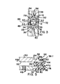
- the vertical member 10 which is preferably an aluminium extrusion, has a central core 14 with four arms 16. radiating from the core. Each arm 16 is at right angles with respect to the adjacent arms. At the outer end of each arm 16 there is a right angled element 18, each limb of each right angled element having a lip 20 extending along the free edge thereof.
- This structure provides four cavities 22 and a slot-like entrance 24 to each cavity. The entrances 24 are bounded by those edges of the elements 18 which have the lips 20 extending therealong.
- the member 12 which is also preferably constituted by an aluminium extrusion, comprises (see particularly Figure 3) a vertical web 26 and two vertically spaced, horizontal flanges 28 protruding from one face of the web 26.
- the web 26 extends both above the top flange 28 and below the bottom flange 28 and has, along each of the free edges thereof, an element 30.
- the elements 30 are at right angles to the web 26 and each has a lip 32 along the free edge thereof.
- each flange 28 there is an element 34 which, in section, is of right angled form.
- an element 34 which, in section, is of right angled form.
- a lip 36 Along one free edge of each element 34 there is a lip 36. It will be seen that the lips 32 and 36 bound two slot-like entrances 38 leading to two cavities 40. Portions 42 of the elements 34 protrude towards one another and bound a slot-like entrance 44 to the main cavity 46 of the member 12.
- reference numerals 48 designate two locking arms which join the members 10 and 12.
- One of these arms can also be seen in Figure 2 and a small portion of each arm can be seen in Figure 1.
- Each arm 48 comprises an outer face 50 and an inner face 52.
- 're-entrant' is meant that the grooves 54 have slot-like entrances which are narrower than inner parts of the grooves.
- a further groove 56 is between each groove 54 and the adjacent end of the arm 48 there is a further groove 56 (see particularly Figure 5).
- Each groove 56 has one bounding face 58 ' which intersects the face 50 at right angles and a face 60 which is oblique zo the face 50, the faces 58 and 60 being so arranged that.the mouth of each groove 56 is wider than its base.
- Protrusions 62 are provided where the faces 58 intersect the faces 50.
- the faces 60 of the grooves 56 intersect curved end faces 64 of the arms 48 to form teeth 66. It. will be noted that the apex of each tooth 66 is set back with respect to the face 50.
- Each face 52 has therein a groove 68 of rectangular cross section and each groove 68 lies just to one side of the centre of its arm.
- the rib 70 has side faces which are at right angles to the face 52 and a top face which is arcuate when viewed in section.
- the groove 68 of each arm 48 receives the rib 70 of the other arm.
- the arms 48 are of the same cross sectional shape, one being rotated through 180° about a transverse central axis with respect to,the other.
- the arms can be produced by extruding an aluminium bar of the desired cross sectional form and then cutting it transversely.
- a spring clip 72 (see particularly Figure 5) of resilient synthetic plastics material secures the arms 48 to one another at the end remote from the member 10 and prevents these ends of the arms 48 moving apart.
- the clip 72 comprises a central portion 76 which lies between the faces 52 and a connecting section in the form of two hook portions 78.
- the hook portions 78 extend from the central portion 76 to beyond the ends of the arms 48 and curve around to join end sections 80 of the clip.
- the end sections 80 lie outwardly of the arms 48 and each includes a projection which seats in the groove 56 and a recess which receives one of the teeth 66.
- the central portion 76 includes two diverging limbs 82 which bear one on each arm 48.
- One of the arms 48 is drilled and tapped at 84 and 86 (see Figure 2) so that it is capable of receiving two Allen screws one of which is shown at 88.
- the single Allen screw, ⁇ when tightened, is normally sufficient to cause the members 10 and 12 to be secured to one another but there are instances where two Allen screws are preferred.
- the arms 48 are pushed into the main cavity 46 of the member 12.
- the member 12 is orientated with respect to the arms 48 so that the Allen screw moves along the entrance 44 to the main cavity 46 (see particularly Figures 2 and 3).
- the Allen screw 88 is turned until its inner end lies within the arm 48.
- the ends of the arms 48 remote from the clip 72 are then squeezed towards one another so that the arms converge and the tips thereof adjacent the teeth 66 touch.
- squeezing is achieved by pressing on the screw 88. Squeezing causes the limbs 82 to be deflected and reduces the angle between them so that a restoring force tending to displace the arms 48 back to their parallel condition comes into existence.
- the arms 48 are then presented to one of the-entrances 24. In their converging condition, the width of the pair of arms, measured across the crests of the teeth 66, is less than that of the entrance 24.
- the teeth 66 enter the cavity 22.
- the portions 82 force the arms apart so that the"lips 20 enter the grooves 56.
- the force exerted by the limbs 82 of the clip 72 is such that there is sufficient friction between the member 10 and the arms 48 to prevent the arms 48 from slipping down the member 10.
- the Allen screw 88 is then tightened so that its inner end moves across the gap between the arms 48 and bears on the other arm to force them apart. This has the effect of forcing the arms 48 into engagement with the elements 18 of the member 10.
- the member 12 can be rotated through 180 0 about its.longitudinal axis with respect to the position shown in Figure 3.
- the Allen screw is inserted.
- the portion 76 and the limbs 82 can be omitted.
- resilient material is not required and a short length of an aluminium or non-resilient synthetic plastics material extrusion suffices.
- a clip of this nature prevents the end portions of the arms 48 from moving apart but exerts no significant restoring force. It will be understood that all the forms of clip disclosed protect the teeth 66 with which they are associated. Should the left hand teeth in Figures 1, 2 and 4 be damaged, then the arms 48 can be turned around and the teeth 66 previously covered by the clip brought into use.
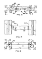
- the members 10.1 and 10.2 can be elongate columns and there can be a series of vertically spaced pairs of arms 48 joining the columns.
- a cover strip 92 ( Figure 6) can be provided.
- the cover strip 92 has two ribs 94 on the rear face thereon, the cross sectional shapes of the ribs 94 being compatible with that of the grooves 54 so that the ribs 94 can snap into the grooves 54 and hold the cover strip 92 in place.
- the arms are enclosed by a member designated 96.
- the cross section of the member 96 can be the same'of that as the member 12 and the member can be of a length such that only those portions of the arms 48 which lie outwardly of the faces 58 protrude therefrom.
- the illustrated and described cross sectional shapes of the members 10 and 12 are by way of example only.
- the-vertical member has a cavity with a slot like entrance into which the arms 48 can be inserted, then the cross sectional shape of the remainder of the vertical member can be of any desired form.
- the lips 32 and 36 of the member 12, which define the entrance 38, will also receive the arms 48.
- the members 10.1 and 10.2 in Figure 6 could, if desired, be replaced by two members having the cross sectional shape of the member 12.
- the member 12 has a main cavity 46 which is capable of receiving the two arms 48, the remaining features of the member can be varied depending on the.additional functions that the member is to perform.
- grooves 68 and ribs 70 are not essential and can be omitted. Likewise, if no cover strip 92 is to be used, then the grooves 54 are not required.
- the arms 48 can, as described, be cut from extruded stock or can be cast in 'left' and 'right' hand forms. For some purposes a single tapped bore 84 or 86 is adequate and this bore can be at the centre of the arm.
- each groove 56 In the angle between the face 58 of each groove 56 and its bottom wall there can be a protruding tooth 56.1 (Figure 5).
- This tooth can only be provided in the die cast form. When the arms 48 are forced apart, the teeth 56.1 bite into the lips 20 to further improve the grip.
- the tooth measured at right angles to the section of Figure 5, is relatively narrow to enhance its ability to bite into the lip.
- Two or more teeth 56.1 can be provided in each groove 56, the teeth 56.1 being spaced apart across the groove 56.
- the illustrated member 12 can be replaced by a tube of rectangular cross section. A hole drilled in its walling receives the Allen screw.
- the arms 48 are cut from two pieces of extruded stock.
- a further extrusion having the cross-sectional shape of the clip 72 is used to hold the two pieces of extruded stock together. When cutting takes place it does so at, for example, 30, 45 or 60 degrees to the edge of the extruded stock.
- the end of the member 12 is cut at the same angle.
Landscapes
- Engineering & Computer Science (AREA)
- General Engineering & Computer Science (AREA)
- Mechanical Engineering (AREA)
- Mutual Connection Of Rods And Tubes (AREA)
- Clamps And Clips (AREA)
- Diaphragms For Electromechanical Transducers (AREA)
- Superconductors And Manufacturing Methods Therefor (AREA)
Priority Applications (1)
| Application Number | Priority Date | Filing Date | Title |
|---|---|---|---|
| AT82304741T ATE25541T1 (de) | 1981-09-18 | 1982-09-09 | Rahmenverbindung. |
Applications Claiming Priority (4)
| Application Number | Priority Date | Filing Date | Title |
|---|---|---|---|
| NZ198408 | 1981-09-18 | ||
| NZ19840881A NZ198408A (en) | 1981-09-18 | 1981-09-18 | Showcase or shelving framework |
| NZ20051382A NZ200513A (en) | 1982-05-04 | 1982-05-04 | Showcase or shelving framework |
| NZ200513 | 1982-05-04 |
Publications (3)
| Publication Number | Publication Date |
|---|---|
| EP0075417A2 true EP0075417A2 (de) | 1983-03-30 |
| EP0075417A3 EP0075417A3 (en) | 1983-06-29 |
| EP0075417B1 EP0075417B1 (de) | 1987-02-25 |
Family
ID=26650490
Family Applications (1)
| Application Number | Title | Priority Date | Filing Date |
|---|---|---|---|
| EP82304741A Expired EP0075417B1 (de) | 1981-09-18 | 1982-09-09 | Rahmenverbindung |
Country Status (10)
| Country | Link |
|---|---|
| US (1) | US4485597A (de) |
| EP (1) | EP0075417B1 (de) |
| AU (1) | AU547899B2 (de) |
| BR (1) | BR8205472A (de) |
| CA (1) | CA1184734A (de) |
| DE (1) | DE3234206A1 (de) |
| DK (1) | DK416782A (de) |
| FI (1) | FI823218L (de) |
| GB (2) | GB2109500B (de) |
| NO (1) | NO823165L (de) |
Cited By (5)
| Publication number | Priority date | Publication date | Assignee | Title |
|---|---|---|---|---|
| FR2585801A1 (fr) * | 1985-08-01 | 1987-02-06 | Ceralnor | Dispositif d'assemblage de profiles comportant des bras basculant autour d'une zone d'articulation |
| FR2665512A1 (fr) * | 1990-07-11 | 1992-02-07 | Technal Sa | Dispositif pour la liaison de trois profiles metalliques. |
| WO1992021887A1 (en) * | 1991-06-05 | 1992-12-10 | Maxibit Ab | Device for attaching an expandable member to a profiled section |
| AT2335U1 (de) * | 1997-04-15 | 1998-08-25 | Wisar Wyser & Anliker Ag | Verbindungselement |
| DE102006022250A1 (de) * | 2006-05-12 | 2007-11-15 | Deutsches Zentrum für Luft- und Raumfahrt e.V. | Haltesystem, Haltevorrichtung und Träger |
Families Citing this family (44)
| Publication number | Priority date | Publication date | Assignee | Title |
|---|---|---|---|---|
| CH654990A5 (de) * | 1981-10-30 | 1986-03-27 | Fehlbaum & Co | Traggestell. |
| US4556337A (en) * | 1983-03-07 | 1985-12-03 | Framelock International Pty. Limited | Connector for framing system |
| GB2137795B (en) * | 1983-04-06 | 1987-04-01 | Michael Peter Gifford Hull | Sign posts |
| US4700469A (en) * | 1986-03-24 | 1987-10-20 | General Motors Corporation | Detachable clamp for fixturing heat exchanger core assemblies for brazing in combination with the heat exchanger core |
| US5319901A (en) * | 1991-06-14 | 1994-06-14 | Goldsworthy W Brandt | Bifurcated column joint system for electrical transmission tower |
| US5285613A (en) * | 1992-01-31 | 1994-02-15 | Goldsworthy W Brandt | Pultruded joint system and tower structure made therewith |
| US4690192A (en) * | 1986-04-29 | 1987-09-01 | Johann Stilling | Replaceable awning |
| US5095677A (en) * | 1986-09-22 | 1992-03-17 | Les Concepts Polystand Inc. | Combination for use in mounting a modular system |
| US4725030A (en) * | 1986-12-29 | 1988-02-16 | Hospital Systems, Inc. | Removable bracket for attachment to rail |
| US4787768A (en) * | 1988-03-02 | 1988-11-29 | Interlock Structures International, Inc. | Fastener apparatus |
| AU619366B2 (en) * | 1988-12-16 | 1992-01-23 | Paul H. Hartman | Radially expandable edge connector system |
| US4942975A (en) * | 1989-07-05 | 1990-07-24 | The United State Of America As Represented By The Secretary Of The Navy | Container connector having a skewed installation configuration |
| US5048995A (en) * | 1990-03-01 | 1991-09-17 | Skyline Displays, Inc. | Coupler for tubular frame members |
| US5067294A (en) * | 1990-07-30 | 1991-11-26 | Mcgowan Bruce | Partition assembly |
| US5209035A (en) * | 1991-01-10 | 1993-05-11 | Steelcase Inc. | Utility panel system |
| US5203135A (en) * | 1991-03-05 | 1993-04-20 | Hamilton Industries, Inc. | Connection for hollow structural members |
| DE4221387C2 (de) * | 1992-06-30 | 1996-02-29 | Mero Raumstruktur Gmbh & Co | Gitterträger, insbesondere für Raumfachwerke |
| US5499885A (en) * | 1993-05-06 | 1996-03-19 | Chapman; William A. | Apparatus for joining structural components |
| ES2121645B1 (es) * | 1994-11-21 | 1999-06-16 | Munoz Carcedo Jose | Construccion metalica modular desmontable y versatil. |
| FR2731246B1 (fr) * | 1995-03-02 | 1997-05-30 | Secalt | Poutre-treillis, notamment pour former un garde-corps porteur de passerelle suspendue |
| US6301846B1 (en) | 1996-12-24 | 2001-10-16 | Steelcase Development Inc. | Knock-down portable partition system |
| US6910306B2 (en) | 1996-12-24 | 2005-06-28 | Steelcase Development Corporation | Knock-down portable partition system |
| US5899035A (en) * | 1997-05-15 | 1999-05-04 | Steelcase, Inc. | Knock-down portable partition system |
| US6546684B2 (en) | 1998-04-15 | 2003-04-15 | Steelcase Development Corporation | Partition panel |
| CA2294426C (en) * | 1997-06-19 | 2006-08-15 | Keith Owen Lewcock | Improvements relating to structural framework systems |
| US6036398A (en) * | 1998-06-22 | 2000-03-14 | Theodorou; Antonis | Extruded frame member for structural connection and method of forming same |
| DE29900957U1 (de) * | 1999-01-21 | 1999-05-20 | Schueco Int Kg | Offenes Hohlprofil |
| CA2287925C (en) * | 1999-10-29 | 2004-06-08 | Force Et Forme | Support post with adjustable accessory supports |
| US6959520B2 (en) * | 2000-07-03 | 2005-11-01 | Hartman Paul H | Demand side management structures |
| US6672026B2 (en) * | 2002-05-03 | 2004-01-06 | Creative Pultrusions, Inc. | Pultruded I-bar with clip fittings enabling automated grating panel assembly |
| DE20212811U1 (de) * | 2002-08-15 | 2003-12-18 | Rixen, Wolfgang, Dipl.-Ing. | Parallelverbinder |
| US20080036179A1 (en) * | 2002-11-27 | 2008-02-14 | Andersen John I | Systems and methods for providing a towing apparatus having an integral ball |
| US6908099B2 (en) * | 2002-11-27 | 2005-06-21 | Andersen Manufacturing, Inc. | Systems and methods for providing aluminum hitch components |
| US7578110B2 (en) * | 2004-06-07 | 2009-08-25 | Jenkins Joseph W | Modular frame connector system |
| KR100886695B1 (ko) | 2008-11-25 | 2009-03-04 | (주)에이.티.아이 | 결합용 홀더를 갖는 알루미늄 프로파일 |
| US8209917B1 (en) * | 2009-05-14 | 2012-07-03 | DeZaio Productions, Inc. | Temporary, non-load bearing wall assembly |
| US8474218B2 (en) * | 2010-09-16 | 2013-07-02 | Robert Spencer Hodgson | Modular inter-locking exterior wall system |
| US8523217B2 (en) | 2011-05-03 | 2013-09-03 | John I. Andersen | Vehicle frame for trailer coupler system |
| AU2011232748B2 (en) * | 2011-10-05 | 2016-05-26 | Danpal Australia Pty Limited | Truss System |
| US8474221B1 (en) | 2012-01-20 | 2013-07-02 | Trident Industries, LLC | Telescoping fiberglass utility pole |
| US9133625B2 (en) * | 2013-12-18 | 2015-09-15 | Moulure Alexandria Moulding | Sheathing element for covering preexisting physical structures |
| US9577571B2 (en) * | 2015-04-17 | 2017-02-21 | Moti Atia | Solar panel mounting apparatus with enhanced strength |
| US10723188B2 (en) | 2016-02-01 | 2020-07-28 | Andersen Manufacturing, Inc. | Lightweight gooseneck-mounted trailer hitch |
| US10662650B2 (en) * | 2017-10-31 | 2020-05-26 | Vention Inc. | T-slot extrusion structure |
Citations (8)
| Publication number | Priority date | Publication date | Assignee | Title |
|---|---|---|---|---|
| FR1361398A (fr) * | 1963-04-02 | 1964-05-22 | Ensemble d'éléments de construction d'ossatures, charpentes ou similaires | |
| FR2000838A1 (de) * | 1968-01-26 | 1969-09-12 | Jankowski Johannes | |
| DE2108342A1 (de) * | 1971-02-22 | 1972-09-07 | Conrad Martin Kg | Rohrverbindung |
| FR2129259A5 (de) * | 1971-03-19 | 1972-10-27 | Nicolas Roger | |
| DE7119423U (de) * | 1973-01-04 | Goetz Metallbau Gmbh | Thermisch isoliertes Verbundprofil | |
| US3966342A (en) * | 1974-10-25 | 1976-06-29 | Seiki Hanbai Co., Ltd. | Interior structure frame assembly |
| FR2297020A1 (fr) * | 1975-01-13 | 1976-08-06 | Sodadi Fabrication Diffusion | Profile metallique pour mobilier |
| FR2508120A1 (fr) * | 1981-06-18 | 1982-12-24 | Provansal Jean Benoit | Piece d'assemblage retractable |
Family Cites Families (5)
| Publication number | Priority date | Publication date | Assignee | Title |
|---|---|---|---|---|
| GB686249A (en) * | 1950-02-17 | 1953-01-21 | Collaro Ltd | Improvements relating to connectors for pipes or tubes |
| US2850304A (en) * | 1955-10-20 | 1958-09-02 | R & B Wagner Inc | Pipe coupling having an internal expanding sleeve |
| DE2103504C3 (de) * | 1971-01-15 | 1974-06-20 | Mannesmann Leichtbau Gmbh, 8000 Muenchen | Verbinder für Profilrohre |
| AT332084B (de) * | 1971-04-13 | 1976-09-10 | Kreusel Ulrich | Eck- oder stumpfverbindung von hohlprofilen fur fenster, turen, gelander od.dgl. |
| HU162416B (de) * | 1971-05-06 | 1973-02-28 |
-
1982
- 1982-09-08 GB GB08225549A patent/GB2109500B/en not_active Expired
- 1982-09-09 EP EP82304741A patent/EP0075417B1/de not_active Expired
- 1982-09-15 DE DE19823234206 patent/DE3234206A1/de not_active Withdrawn
- 1982-09-15 AU AU88421/82A patent/AU547899B2/en not_active Ceased
- 1982-09-15 CA CA000411510A patent/CA1184734A/en not_active Expired
- 1982-09-16 US US06/418,656 patent/US4485597A/en not_active Expired - Fee Related
- 1982-09-17 FI FI823218A patent/FI823218L/fi not_active Application Discontinuation
- 1982-09-17 BR BR8205472A patent/BR8205472A/pt unknown
- 1982-09-17 NO NO823165A patent/NO823165L/no unknown
- 1982-09-17 DK DK416782A patent/DK416782A/da not_active Application Discontinuation
-
1985
- 1985-06-04 GB GB08514020A patent/GB2158545B/en not_active Expired
Patent Citations (8)
| Publication number | Priority date | Publication date | Assignee | Title |
|---|---|---|---|---|
| DE7119423U (de) * | 1973-01-04 | Goetz Metallbau Gmbh | Thermisch isoliertes Verbundprofil | |
| FR1361398A (fr) * | 1963-04-02 | 1964-05-22 | Ensemble d'éléments de construction d'ossatures, charpentes ou similaires | |
| FR2000838A1 (de) * | 1968-01-26 | 1969-09-12 | Jankowski Johannes | |
| DE2108342A1 (de) * | 1971-02-22 | 1972-09-07 | Conrad Martin Kg | Rohrverbindung |
| FR2129259A5 (de) * | 1971-03-19 | 1972-10-27 | Nicolas Roger | |
| US3966342A (en) * | 1974-10-25 | 1976-06-29 | Seiki Hanbai Co., Ltd. | Interior structure frame assembly |
| FR2297020A1 (fr) * | 1975-01-13 | 1976-08-06 | Sodadi Fabrication Diffusion | Profile metallique pour mobilier |
| FR2508120A1 (fr) * | 1981-06-18 | 1982-12-24 | Provansal Jean Benoit | Piece d'assemblage retractable |
Cited By (7)
| Publication number | Priority date | Publication date | Assignee | Title |
|---|---|---|---|---|
| FR2585801A1 (fr) * | 1985-08-01 | 1987-02-06 | Ceralnor | Dispositif d'assemblage de profiles comportant des bras basculant autour d'une zone d'articulation |
| EP0216650A1 (de) * | 1985-08-01 | 1987-04-01 | CERALNOR: Société Anonyme | Profilverbindungsvorrichtung mit an einer Gelenkverbindung kippbaren Armen |
| FR2665512A1 (fr) * | 1990-07-11 | 1992-02-07 | Technal Sa | Dispositif pour la liaison de trois profiles metalliques. |
| WO1992021887A1 (en) * | 1991-06-05 | 1992-12-10 | Maxibit Ab | Device for attaching an expandable member to a profiled section |
| AT2335U1 (de) * | 1997-04-15 | 1998-08-25 | Wisar Wyser & Anliker Ag | Verbindungselement |
| DE102006022250A1 (de) * | 2006-05-12 | 2007-11-15 | Deutsches Zentrum für Luft- und Raumfahrt e.V. | Haltesystem, Haltevorrichtung und Träger |
| DE102006022250B4 (de) * | 2006-05-12 | 2012-10-25 | Deutsches Zentrum für Luft- und Raumfahrt e.V. | Haltesystem |
Also Published As
| Publication number | Publication date |
|---|---|
| NO823165L (no) | 1983-03-21 |
| BR8205472A (pt) | 1983-08-23 |
| AU547899B2 (en) | 1985-11-07 |
| GB2109500B (en) | 1986-01-15 |
| CA1184734A (en) | 1985-04-02 |
| GB8514020D0 (en) | 1985-07-10 |
| GB2158545A (en) | 1985-11-13 |
| EP0075417A3 (en) | 1983-06-29 |
| US4485597A (en) | 1984-12-04 |
| GB2109500A (en) | 1983-06-02 |
| DE3234206A1 (de) | 1983-04-07 |
| GB2158545B (en) | 1986-01-22 |
| DK416782A (da) | 1983-03-19 |
| FI823218L (fi) | 1983-03-19 |
| AU8842182A (en) | 1983-03-24 |
| EP0075417B1 (de) | 1987-02-25 |
| FI823218A0 (fi) | 1982-09-17 |
Similar Documents
| Publication | Publication Date | Title |
|---|---|---|
| EP0075417A2 (de) | Rahmenverbindung | |
| US3592493A (en) | Constructional systems | |
| US5363622A (en) | Fire-rated drywall suspension system | |
| US3901612A (en) | Releaseable joint | |
| CA1133565A (en) | Device for assembling and connecting to one another constructive elements particularly panels for furniture and like | |
| US4365907A (en) | Fastening devices | |
| US4168922A (en) | Frame jointing assembly and the like | |
| US4505083A (en) | Delineated ceiling grid in suspended ceiling | |
| US4653652A (en) | Construction system | |
| US5642957A (en) | Tubular member connector | |
| CA2139051A1 (en) | Connecting mechanism for tubular frame elements | |
| EP0436702A1 (de) | Elastischer streifen und befestigungselement für einen glatt abschliessenden schutzstreifenaufbau | |
| US4348127A (en) | Connector for extruded sections such as picture frame members | |
| US4207014A (en) | Hollow rod joint connection | |
| CA1059290A (en) | Corner jointing assembly and the like | |
| EP0068583B1 (de) | Verbindungseinrichtung zur Verbindung von Platten oder ähnlichen Konstruktionselementen | |
| US4236846A (en) | Tube joint | |
| NZ198408A (en) | Showcase or shelving framework | |
| EP0383427A2 (de) | Reklametafel-Bausatz | |
| EP0169697A1 (de) | Verbindungsanordnung | |
| GB2077879A (en) | Structural joint | |
| US4123180A (en) | Tube connector | |
| EP0165259A1 (de) | Verbindungseinheit für hohlprofile | |
| US4583878A (en) | Framing system | |
| GB2174783A (en) | Jointing system |
Legal Events
| Date | Code | Title | Description |
|---|---|---|---|
| PUAI | Public reference made under article 153(3) epc to a published international application that has entered the european phase |
Free format text: ORIGINAL CODE: 0009012 |
|
| AK | Designated contracting states |
Designated state(s): AT BE CH FR IT LI LU NL SE |
|
| PUAL | Search report despatched |
Free format text: ORIGINAL CODE: 0009013 |
|
| AK | Designated contracting states |
Designated state(s): AT BE CH FR IT LI LU NL SE |
|
| 17P | Request for examination filed |
Effective date: 19831217 |
|
| GRAA | (expected) grant |
Free format text: ORIGINAL CODE: 0009210 |
|
| AK | Designated contracting states |
Kind code of ref document: B1 Designated state(s): AT BE CH FR IT LI LU NL SE |
|
| PG25 | Lapsed in a contracting state [announced via postgrant information from national office to epo] |
Ref country code: LI Effective date: 19870225 Ref country code: CH Effective date: 19870225 Ref country code: AT Effective date: 19870225 |
|
| REF | Corresponds to: |
Ref document number: 25541 Country of ref document: AT Date of ref document: 19870315 Kind code of ref document: T |
|
| PG25 | Lapsed in a contracting state [announced via postgrant information from national office to epo] |
Ref country code: SE Effective date: 19870228 |
|
| ITF | It: translation for a ep patent filed |
Owner name: ING. C. GREGORJ S.P.A. |
|
| ET | Fr: translation filed | ||
| REG | Reference to a national code |
Ref country code: CH Ref legal event code: PL |
|
| PG25 | Lapsed in a contracting state [announced via postgrant information from national office to epo] |
Ref country code: LU Free format text: LAPSE BECAUSE OF NON-PAYMENT OF DUE FEES Effective date: 19870930 |
|
| PGFP | Annual fee paid to national office [announced via postgrant information from national office to epo] |
Ref country code: NL Payment date: 19870930 Year of fee payment: 6 |
|
| PLBE | No opposition filed within time limit |
Free format text: ORIGINAL CODE: 0009261 |
|
| STAA | Information on the status of an ep patent application or granted ep patent |
Free format text: STATUS: NO OPPOSITION FILED WITHIN TIME LIMIT |
|
| 26N | No opposition filed | ||
| PGFP | Annual fee paid to national office [announced via postgrant information from national office to epo] |
Ref country code: FR Payment date: 19890825 Year of fee payment: 8 |
|
| PGFP | Annual fee paid to national office [announced via postgrant information from national office to epo] |
Ref country code: BE Payment date: 19890929 Year of fee payment: 8 |
|
| ITTA | It: last paid annual fee | ||
| PG25 | Lapsed in a contracting state [announced via postgrant information from national office to epo] |
Ref country code: NL Effective date: 19900401 |
|
| NLV4 | Nl: lapsed or anulled due to non-payment of the annual fee | ||
| PG25 | Lapsed in a contracting state [announced via postgrant information from national office to epo] |
Ref country code: BE Effective date: 19900930 |
|
| BERE | Be: lapsed |
Owner name: WORRALLO ANTHONY CHARLES Effective date: 19900930 |
|
| PG25 | Lapsed in a contracting state [announced via postgrant information from national office to epo] |
Ref country code: FR Effective date: 19910530 |
|
| REG | Reference to a national code |
Ref country code: FR Ref legal event code: ST |