EP0075343B1 - Laminar flow element - Google Patents
Laminar flow element Download PDFInfo
- Publication number
- EP0075343B1 EP0075343B1 EP82201059A EP82201059A EP0075343B1 EP 0075343 B1 EP0075343 B1 EP 0075343B1 EP 82201059 A EP82201059 A EP 82201059A EP 82201059 A EP82201059 A EP 82201059A EP 0075343 B1 EP0075343 B1 EP 0075343B1
- Authority
- EP
- European Patent Office
- Prior art keywords
- disks
- grooves
- inlet
- outlet
- openings
- Prior art date
- Legal status (The legal status is an assumption and is not a legal conclusion. Google has not performed a legal analysis and makes no representation as to the accuracy of the status listed.)
- Expired
Links
- 239000012530 fluid Substances 0.000 claims abstract description 50
- 238000011144 upstream manufacturing Methods 0.000 description 9
- 238000005259 measurement Methods 0.000 description 3
- 238000007789 sealing Methods 0.000 description 2
- 238000010276 construction Methods 0.000 description 1
- 230000001419 dependent effect Effects 0.000 description 1
- 238000010586 diagram Methods 0.000 description 1
- 238000005530 etching Methods 0.000 description 1
- 238000009434 installation Methods 0.000 description 1
- 238000012423 maintenance Methods 0.000 description 1
- 238000000034 method Methods 0.000 description 1
- 238000012986 modification Methods 0.000 description 1
- 230000004048 modification Effects 0.000 description 1
- 238000004804 winding Methods 0.000 description 1
Images


Classifications
-
- G—PHYSICS
- G01—MEASURING; TESTING
- G01F—MEASURING VOLUME, VOLUME FLOW, MASS FLOW OR LIQUID LEVEL; METERING BY VOLUME
- G01F1/00—Measuring the volume flow or mass flow of fluid or fluent solid material wherein the fluid passes through a meter in a continuous flow
- G01F1/05—Measuring the volume flow or mass flow of fluid or fluent solid material wherein the fluid passes through a meter in a continuous flow by using mechanical effects
- G01F1/34—Measuring the volume flow or mass flow of fluid or fluent solid material wherein the fluid passes through a meter in a continuous flow by using mechanical effects by measuring pressure or differential pressure
- G01F1/36—Measuring the volume flow or mass flow of fluid or fluent solid material wherein the fluid passes through a meter in a continuous flow by using mechanical effects by measuring pressure or differential pressure the pressure or differential pressure being created by the use of flow constriction
- G01F1/40—Details of construction of the flow constriction devices
Definitions
- the invention relates to a laminar flow element for mounting inside a fluid flow channel, which flow element is built up from flat disks, which are provided with grooves on one side ending in an outlet opening in the disk, which disks are piled up into a package on account of which the grooves form channels of such dimensions that the fluid flows laminar through said channels and the outlet openings together form an outlet channel.
- a laminar flow element of this type is already described in the U.S. Patent 3,851,526.
- Such laminar flow elements are, as illustrated in this American Patent 3,851,526, applied for instance in fluid flow meters, in which the total fluid flow quantity in a fluid flow channel is measured on the basis of a small part of said fluid flow, branched from the main flow through a measuring channel in the form of a thin tube of such dimensions that the flow through said measuring channel is laminar.
- a first requirement for such measurements is, that the fluid flow is divided into a main flow and a measuring flow in such a way that there is a precise relationship between said two flows. To achieve that, the flow in the fluid flow channel itself must be laminar. That is realized by means of a flow element according to the U.S.
- Patent 3,851,526, which is provided with a large number of flow channels in which the flow is laminar.
- Said laminar flow element is placed inside the fluid flow channel in such a way, that the fluid is forced to flow through channels in said flow element.
- a laminar measuring channel is connected to the fluid flow channel.
- the percentage of the fluid flowing through this measuring channel must be accurately known.
- Across the flow element, placed inside the main fluid channel a pressure drop is building up and as long as the flow is laminar the flow velocity is directly proportional to said pressure drop and inversely proportional to the viscosity.
- a fixed relation can be determined between the flow in the measuring channel and the flow in the main flow channel. Details thereof are known to the expert in this field and need no further explanation.
- the disks from which the known flow element illustrated in the U.S. Patent 3,851,526, is built up are provided with grooves running from the edge of the disk to a centrally positioned opening in the disk.
- said disks are positioned with the aid of suitable expedients, for instance centralizing pins which run through further openings, specially intended thereto, or a pin having the same diameter as the central opening onto which the disks are received during assembly.
- the package of the disks which are in this way correctly mutually positioned, is pressed inside the fluid flow channel against a thereto intended shoulder by means of a screw type element, which can be screwed into a part of the wall of the fluid flow channel upstream of said package, which wall part is provided with thread.
- This screw type element has a central bore extending from the upstream end of said element and furthermore a number of radial bores ending at one side into said central bore and ending at the other side in a space outside said screw type upstream of the package of disks.
- the fluid flows through the central bore and through said radial bores of the screw type element into the space between this screw type element and the channel wall and upstream of the package of disks. From said space the fluid flows through the grooves running from the cylindrical outer wall of said package of disks to the central opening of said package. Because this central opening is sealed at the upstream side of said package by the end wall of the screw type element the fluid will flow further downstreams to the fluid flow channel.
- a disadvantage of this construction is that the screw type element pressing the package of disks against the shoulder in the channel wall has a very complicated form because the fluid must be guided through radial openings into this screw type element to the cylindrical outer wall of the package of disks. Furthermore said screw type element takes care of the sealing of the central outlet opening at the upstream side.
- the shape of the channel and the dimensions of the disks must be chosen such, that there is sufficient free space left around said package of disks at the input side of the laminar flow channels through this package.
- the total fluid resistance of this known flow element can be adapted by a suitable choice of the number of disks combined into one package. The greater this number of disks is, the smaller the total flow resistance will be. Based on one type of disks with all the same number of channels only a step by step variation in the flow resistance is possible. Only when disks having different numbers of channels are used it is possible to get a better approximation of a desired value of said flow resistance.
- An object of the invention is now to eliminate at least partly the above mentioned disadvantages and to provde a laminar flow element which can be mounted in a simple way and with simple means and of which the flow resistance value can be adjusted much more accurately, whereas in principle disks of only one and the same type are used.
- a laminar flow element of the above mentioned type which is characterized in that the grooves in the disks run between an excentrically made inlet opening and said outlet opening, which inlet openings together form an inlet channel and that the outer disks of a package do not have grooves and only comprise an inlet respectively outlet opening or openings.
- both the inlet and outlet opening or openings are positioned eccentrically. This gives the possibility of providing one central opening to be used for the mounting means during the assembly of a package of disks, such as a bolt and a nut. From a technical constructional point of view this leads to a very simple configuration.
- each grooved disk comprises one inlet opening and one outlet opening diametrically opposite each other.
- the outer disks of the package only have one eccentrically positioned opening, whereby the opening in the upstream front disk is aligned with the inlet openings of the intermediate disks and the opening in the downstream rear disk is aligned with the outlet openings of the intermediate disks.
- Fig. 1 illustrates a first embodiment of a disk, forming part of the laminar flow element according to the invention.
- Said round disk is provided with two diametrically opposed openings 2 and 3 with grooves 4 running between said openings into one side wall of said disk.
- the openings 2 and 3 in this embodiment have the shape of a crescent but may also have a different shape.
- Said disk has in the center a central square opening 5 which on the one hand functions to maintain said disks in the correct position and on the other hand offers the possibility to connect said disks onto each other for instance by means of a bolt and nut to assemble a package. It is of course also possible to use a round hole 5 and to maintain said disks in the correct position during assemblage by means of one or more adjusting pins.
- FIG. 1b illustrates a partial cross section through the part of a disk containing the grooves 4, especially according to line Ib in Fig. 1a.
- Said grooves can be made in the disk for instance by means of etching, although also other methods may be applied.
- the dimensions of said grooves must be chosen such that, when the disks are placed onto each other and the grooves are forming channels, the flow through said channels is laminar. It is known to the expert in this field how said grooves have to be dimensioned to achieve a laminar flow. More details can be found for instance in said U.S. Patent 3,851,526.
- Fig. 2 shows in a schematic way in which manner a laminar flow element can be built using said disks.
- Two disks of the type as illustrated in Fig. 1, i.e. the disks 12 and 13 are placed onto each other and at the front end rear side the disks 11 and 14 respectively are provided only having an Input opening 15 respectively an output opening 16 and not containing grooves.
- the fluid will enter through the inlet opening 15 of the cover disk 11 and the therewith aligned openings 17 and 18 of the flow disks 12 and 13 respectively.
- the flow resistance of this laminar flow element is dependent on the number of disks assembled together into one package. The larger the number of disks, the smaller the flow resistance. If only disks with one and the same number of grooves are used, then in this way only a step by step variation of the flow resistance is possible.
- Fig. 3a indicates that, because of the configuration of the disks, it is possible to increase the flow resistance by serially linking further packages.
- the disks 21, 22, 23 and 24 are forming a package of disks similar to the package illustrated in Fig. 2.
- the disks 25, 26 and 27 are added forming together with the disk 24 also a . similar package.
- said disks 21 until 27 can be considered as the serially linked configuration of two packages of the type illustrated separately in Fig. 2.
- the total flow resistance of said flow element has been increased.
- This combination can be compared with an electrical resistance network in which groups of mutually parallel resistances are combined into a serial circuit.
- This electrical network illustrated in Fig. 3b is analogue to the combination of flow elements illustrated in Fig. 3a.
- the resistances 31, 32 and 33 and also the resistances 34, 35 and 36 are mutually connected in parallel.
- the combination of the resistances 31-33 is connected in series with the combination of the resistances 34-36.
- Fig. 4 illustrates a second embodiment of a disk which can be used in a flow element according to the invention.
- This disk is provided with four openings 41, 42, 43 and 44, which are made eccentrically in the shown way. Between the openings 41 and 42 a first group of grooves 45 is running and a second group of grooves 46 is running between the openings 43 and 44. Furthermore mounting holes 47 and 48 are present to assemble said disks into a package by means of for instance two bolts and nuts.
- Fig. 5 illustrates in which way a number of disks 40 of the shape illustrated in Fig. 4 can be assembled together into a package and illustrates at the same time how the front and rear cover disks are embodied in this case. Also in this figure it is indicated by means of arrows how the fluid will flow via two parallel ways through the flow element. As appears from this figure the front cover disk 51 has only been provided with the openings 41 and 43, whereas the rear cover disk 54 has only the openings 42 and 44. The intermediate disks 52 and 53 are embodied as illustrated in Fig. 4.
- the openings 41 serve as inlet openings for the upper passageway and the openings 42 serve as outlet openings therefore.
- the openings 43 serve as inlet openings and the fluid leaves the element via the openings 44.
- Fig. 4 offers furthermore the possibility of mounting the laminarflow element in another way into the fluid channel.
- the laminar flow elements described so far, are in principle destined for mounting into a fluid channel itself in a way as is illustrated in Fig. 9.
- Fig. 7 illustrates another way of mounting the laminar flow element into the fluid flow channel.
- a baffle 74 is positioned inside the fluid channel 71 in a way illustrated in Fig. 7.
- an opening is made opposite the baffle 74.
- a package of disks 72 is thereafter placed on the side of the fluid channel 71.
- the means by which this package of disks is mounted are not illustrated in detail.
- baffle 74 closingly rests against the package of disks 72 and that there is a free space 73 underneath said package.
- the fluid is now forced to first pass this package of disks in one way to the free space 73 underneath said package as indicated by arrows and from there to pass the package of disks in a second direction to the downstream side of the fluid flow channel.
- Fig. 6 illustrates for this situation in which way the fluid flows through the package of disks, comprising the front cover disk 61, the intermediate grooved disks 62 and 63 and the rear cover disk 64.
- the fluid flows as is indicated by arrows from the point of entry via the upper way, leaves the package at the right hand top corner and is forced to return via the bottom way.
- Fig. 7 The advantage of mounting the package of disks as is illustrated in Fig. 7 is, that the package is easily accessible for mounting and for maintenance without the necessity to interfere in the fluid channel itself.
- Fig. 8 illustrates a third embodiment of the flow disk according to the invention.
- the disk 81 has in this case four openings 82, 83, 84 and 85.
- the first group of grooves 86 runs between the openings 82 and 83 and a second group of grooves 87 runs between the openings 84 and 85.
- a central square hole 88 is positioned functioning for centering and assembling purposes.
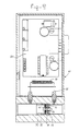
- Fig. 9 finally illustrates an application of the flow element according to the invention in a mass flow meter 97.
- the package of disks 91 is mounted into the channel 90 by means of an externally threaded tube section 92, which is screwed into the left hand part of the channel 90, the inner wall of which is threaded, thereby pushing the package of disks 91 against a shoulder 93 inside said channel.
- an O-ring seal 94 has been placed before the shoulder 93.
- the disks have first been assembled together into a package by means of the bolt 95 and nut 96 and hereafter this package is mounted inside the channel 90 with the aid of the threaded element 92.
- a measuring channel 98 is connected to the flow channel.
- the windings 99 around the measuring channel 98 are delivering signals to the electronic circuit 100. Details of the circuit and details of the actual measurement can be found for instance in the already mentioned U.S. Patent 3,851,526.
Landscapes
- Physics & Mathematics (AREA)
- Fluid Mechanics (AREA)
- General Physics & Mathematics (AREA)
- Measuring Volume Flow (AREA)
- External Artificial Organs (AREA)
Abstract
Description
- The invention relates to a laminar flow element for mounting inside a fluid flow channel, which flow element is built up from flat disks, which are provided with grooves on one side ending in an outlet opening in the disk, which disks are piled up into a package on account of which the grooves form channels of such dimensions that the fluid flows laminar through said channels and the outlet openings together form an outlet channel.
- A laminar flow element of this type is already described in the U.S. Patent 3,851,526. Such laminar flow elements are, as illustrated in this American Patent 3,851,526, applied for instance in fluid flow meters, in which the total fluid flow quantity in a fluid flow channel is measured on the basis of a small part of said fluid flow, branched from the main flow through a measuring channel in the form of a thin tube of such dimensions that the flow through said measuring channel is laminar. A first requirement for such measurements is, that the fluid flow is divided into a main flow and a measuring flow in such a way that there is a precise relationship between said two flows. To achieve that, the flow in the fluid flow channel itself must be laminar. That is realized by means of a flow element according to the U.S. Patent 3,851,526, which is provided with a large number of flow channels in which the flow is laminar. Said laminar flow element is placed inside the fluid flow channel in such a way, that the fluid is forced to flow through channels in said flow element. In front and behind the laminar flow element a laminar measuring channel is connected to the fluid flow channel. To realize an accurate measurement the percentage of the fluid flowing through this measuring channel must be accurately known. Across the flow element, placed inside the main fluid channel a pressure drop is building up and as long as the flow is laminar the flow velocity is directly proportional to said pressure drop and inversely proportional to the viscosity. Depending on the dimensions a fixed relation can be determined between the flow in the measuring channel and the flow in the main flow channel. Details thereof are known to the expert in this field and need no further explanation.
- The disks, from which the known flow element illustrated in the U.S. Patent 3,851,526, is built up are provided with grooves running from the edge of the disk to a centrally positioned opening in the disk. During the installation of the disks inside the fluid flow channel, said disks are positioned with the aid of suitable expedients, for instance centralizing pins which run through further openings, specially intended thereto, or a pin having the same diameter as the central opening onto which the disks are received during assembly. The package of the disks, which are in this way correctly mutually positioned, is pressed inside the fluid flow channel against a thereto intended shoulder by means of a screw type element, which can be screwed into a part of the wall of the fluid flow channel upstream of said package, which wall part is provided with thread. This screw type element has a central bore extending from the upstream end of said element and furthermore a number of radial bores ending at one side into said central bore and ending at the other side in a space outside said screw type upstream of the package of disks.
- During operation the fluid flows through the central bore and through said radial bores of the screw type element into the space between this screw type element and the channel wall and upstream of the package of disks. From said space the fluid flows through the grooves running from the cylindrical outer wall of said package of disks to the central opening of said package. Because this central opening is sealed at the upstream side of said package by the end wall of the screw type element the fluid will flow further downstreams to the fluid flow channel. A disadvantage of this construction is that the screw type element pressing the package of disks against the shoulder in the channel wall has a very complicated form because the fluid must be guided through radial openings into this screw type element to the cylindrical outer wall of the package of disks. Furthermore said screw type element takes care of the sealing of the central outlet opening at the upstream side.
- Furthermore the shape of the channel and the dimensions of the disks must be chosen such, that there is sufficient free space left around said package of disks at the input side of the laminar flow channels through this package.
- Furthermore separate auxiliary means in the form of centralizing elements are necessary during the mounting of a package of disks inside the fluid flow channel.
- The total fluid resistance of this known flow element can be adapted by a suitable choice of the number of disks combined into one package. The greater this number of disks is, the smaller the total flow resistance will be. Based on one type of disks with all the same number of channels only a step by step variation in the flow resistance is possible. Only when disks having different numbers of channels are used it is possible to get a better approximation of a desired value of said flow resistance.
- An object of the invention is now to eliminate at least partly the above mentioned disadvantages and to provde a laminar flow element which can be mounted in a simple way and with simple means and of which the flow resistance value can be adjusted much more accurately, whereas in principle disks of only one and the same type are used.
- This object is reached with a laminar flow element of the above mentioned type which is characterized in that the grooves in the disks run between an excentrically made inlet opening and said outlet opening, which inlet openings together form an inlet channel and that the outer disks of a package do not have grooves and only comprise an inlet respectively outlet opening or openings.
- Thereby it is achieved that the fluid enters the flow element on the frontside without the necessity to guide said fluid first to the cylindrical wall of the element.
- According to a preferred embodiment of the invention both the inlet and outlet opening or openings are positioned eccentrically. This gives the possibility of providing one central opening to be used for the mounting means during the assembly of a package of disks, such as a bolt and a nut. From a technical constructional point of view this leads to a very simple configuration.
- In a further preferred embodiment of the element according to the invention each grooved disk comprises one inlet opening and one outlet opening diametrically opposite each other. Thereby the outer disks of the package only have one eccentrically positioned opening, whereby the opening in the upstream front disk is aligned with the inlet openings of the intermediate disks and the opening in the downstream rear disk is aligned with the outlet openings of the intermediate disks.
- With such an embodied flow element it is possible to place a number of packages of disks onto each other in such a way, that the downstream rear disk of one package at the same time functions as the upstream front disk of the next package succeeding in downstream direction. By this serial linking of packages it is possible to increase the flow resistance of the total combined element. By a correct choice of the number of disks per package and by a correct choice of the number of packages linked in series in this way a large variety of flow resistance values of the laminar flow element can be realized.
- Further advantages and characteristics of the invention will becme clear from the following more detailed description in which reference is made to the attached figures.
- Fig. 1a illustrates a first embodiment of a flow disk for a laminar flow element according to the invention.
- Fig. 1 b illustrates a partial cross section through a disk of Fig. 1a according to line Ib in Fig. 1a.
- Fig. 2 illustrates the composition of a laminar flow element using the disks illustrated in Fig. 1.
- Fig. 3a illustrates the serial linking of packages assembled from disks illustrated in Fig. 1.
- Fig. 3b illustrates the analogue electrical diagram of the flow element according to Fig. 3a.
- Fig. 4 illustrates a second embodiment of the flow disk for a laminar flow element according to the invention.
- Fig. 5 illustrates the composition of a laminar flow element using the disks according to Fig. 4.
- Fig. 6 illustrates a composition of a laminar flow element using the disks according to Fig. 4, destined for other way of mounting.
- Fig. 7 illustrates the application of a laminar flow element according to Fig. 6.
- Fig. 8 illustrates a first embodiment of a flow disk for a laminar flow element according to the invention.
- Fig. 9 illustrates schematically a mass flow meter in which a laminar flow element according to the invention is used.
- Fig. 1 illustrates a first embodiment of a disk, forming part of the laminar flow element according to the invention. Said round disk is provided with two diametrically opposed openings 2 and 3 with grooves 4 running between said openings into one side wall of said disk. The openings 2 and 3 in this embodiment have the shape of a crescent but may also have a different shape. Said disk has in the center a
central square opening 5 which on the one hand functions to maintain said disks in the correct position and on the other hand offers the possibility to connect said disks onto each other for instance by means of a bolt and nut to assemble a package. It is of course also possible to use around hole 5 and to maintain said disks in the correct position during assemblage by means of one or more adjusting pins. Another possibility is to form flat sides at a predetermined edge section which flat sides can be used for centering purposes during assembling of the package. Fig. 1b illustrates a partial cross section through the part of a disk containing the grooves 4, especially according to line Ib in Fig. 1a. Said grooves can be made in the disk for instance by means of etching, although also other methods may be applied. The dimensions of said grooves must be chosen such that, when the disks are placed onto each other and the grooves are forming channels, the flow through said channels is laminar. It is known to the expert in this field how said grooves have to be dimensioned to achieve a laminar flow. More details can be found for instance in said U.S. Patent 3,851,526. - Fig. 2 shows in a schematic way in which manner a laminar flow element can be built using said disks. Two disks of the type as illustrated in Fig. 1, i.e. the
disks disks 11 and 14 respectively are provided only having anInput opening 15 respectively anoutput opening 16 and not containing grooves. As is schematically indicated by means of arrows in Fig. 2 the fluid will enter through the inlet opening 15 of thecover disk 11 and the therewith alignedopenings flow disks disks output openings disks - The flow resistance of this laminar flow element is dependent on the number of disks assembled together into one package. The larger the number of disks, the smaller the flow resistance. If only disks with one and the same number of grooves are used, then in this way only a step by step variation of the flow resistance is possible.
- Fig. 3a indicates that, because of the configuration of the disks, it is possible to increase the flow resistance by serially linking further packages. The
disks disks disk 24 also a . similar package. Together saiddisks 21 until 27 can be considered as the serially linked configuration of two packages of the type illustrated separately in Fig. 2. Also in this figure it is indicated by means of arrows in which way the fluid flows through this flow element. On account of this serial linking of packages the total flow resistance of said flow element has been increased. - This combination can be compared with an electrical resistance network in which groups of mutually parallel resistances are combined into a serial circuit. This electrical network illustrated in Fig. 3b is analogue to the combination of flow elements illustrated in Fig. 3a. The
resistances resistances - A corresponding situation applies to the serial linking of package with laminar flow disks as is illustrated in Fig. 3a. Using only disks having the same number of grooves, it is possible by varying the number of packages linked in series and the number of disks per package, to build up different resistance values, among which many which cannot be realized with one single package of disks.
- Fig. 4 illustrates a second embodiment of a disk which can be used in a flow element according to the invention. This disk is provided with four
openings grooves 46 is running between theopenings holes - Fig. 5 illustrates in which way a number of
disks 40 of the shape illustrated in Fig. 4 can be assembled together into a package and illustrates at the same time how the front and rear cover disks are embodied in this case. Also in this figure it is indicated by means of arrows how the fluid will flow via two parallel ways through the flow element. As appears from this figure thefront cover disk 51 has only been provided with theopenings 41 and 43, whereas the rear cover disk 54 has only theopenings intermediate disks - As is illustrated in Fig. 5 the openings 41 serve as inlet openings for the upper passageway and the
openings 42 serve as outlet openings therefore. For the lower way theopenings 43 serve as inlet openings and the fluid leaves the element via theopenings 44. - Also in this embodiment of the disks it is possible to link a number of packages, if required each with a different number of disks, in series in a way as schematically indicated in Fig. 3a, so that a large number of different resistance values can be realized.
- The embodiment of the disk illustrated in Fig. 4 offers furthermore the possibility of mounting the laminarflow element in another way into the fluid channel. The laminar flow elements described so far, are in principle destined for mounting into a fluid channel itself in a way as is illustrated in Fig. 9. Fig. 7 illustrates another way of mounting the laminar flow element into the fluid flow channel. Inside the fluid channel 71 a
baffle 74 is positioned in a way illustrated in Fig. 7. In the side wall of thefluid channel 71 an opening is made opposite thebaffle 74. In a way which as schematically illustrated in Fig. 7 a package ofdisks 72 is thereafter placed on the side of thefluid channel 71. The means by which this package of disks is mounted are not illustrated in detail. The only important thing is that thebaffle 74 closingly rests against the package ofdisks 72 and that there is afree space 73 underneath said package. The fluid is now forced to first pass this package of disks in one way to thefree space 73 underneath said package as indicated by arrows and from there to pass the package of disks in a second direction to the downstream side of the fluid flow channel. - Fig. 6 illustrates for this situation in which way the fluid flows through the package of disks, comprising the front cover disk 61, the intermediate
grooved disks rear cover disk 64. The fluid flows as is indicated by arrows from the point of entry via the upper way, leaves the package at the right hand top corner and is forced to return via the bottom way. - The advantage of mounting the package of disks as is illustrated in Fig. 7 is, that the package is easily accessible for mounting and for maintenance without the necessity to interfere in the fluid channel itself.
- Fig. 8 illustrates a third embodiment of the flow disk according to the invention. The
disk 81 has in this case fouropenings grooves 86 runs between theopenings grooves 87 runs between theopenings square hole 88 is positioned functioning for centering and assembling purposes. - When a number of these disks is assembled together into a package with an upstream cover disk without grooves and only the
openings openings openings openings - Fig. 9 finally illustrates an application of the flow element according to the invention in a
mass flow meter 97. The package ofdisks 91 is mounted into thechannel 90 by means of an externally threadedtube section 92, which is screwed into the left hand part of thechannel 90, the inner wall of which is threaded, thereby pushing the package ofdisks 91 against ashoulder 93 inside said channel. To obtain a good sealing an O-ring seal 94 has been placed before theshoulder 93. The disks have first been assembled together into a package by means of thebolt 95 and nut 96 and hereafter this package is mounted inside thechannel 90 with the aid of the threadedelement 92. - Before and after the disk package 91 a measuring channel 98 is connected to the flow channel. The windings 99 around the measuring channel 98 are delivering signals to the
electronic circuit 100. Details of the circuit and details of the actual measurement can be found for instance in the already mentioned U.S. Patent 3,851,526. - It will be clear thatthe invention is not limited to the illustrated embodiments, but that also several modifications and changes are possible within the scope of the invention. In the embodiments having a number of groups of grooves, for instance the numbers of grooves in each group can be different, so that the number of possibilities to vary the flow resistance value of a flow element built up from identical disks increases considerably.
- It is also not necessary that the separate grooves in a group are running rectangular, they can also be embodied in a non straight pattern.
Claims (6)
Priority Applications (1)
| Application Number | Priority Date | Filing Date | Title |
|---|---|---|---|
| AT82201059T ATE19432T1 (en) | 1981-09-22 | 1982-08-25 | LAMINAR FLOW ELEMENT. |
Applications Claiming Priority (2)
| Application Number | Priority Date | Filing Date | Title |
|---|---|---|---|
| NL8104354 | 1981-09-22 | ||
| NL8104354A NL8104354A (en) | 1981-09-22 | 1981-09-22 | LAMINARY FLOW ELEMENT. |
Publications (3)
| Publication Number | Publication Date |
|---|---|
| EP0075343A2 EP0075343A2 (en) | 1983-03-30 |
| EP0075343A3 EP0075343A3 (en) | 1984-07-04 |
| EP0075343B1 true EP0075343B1 (en) | 1986-04-23 |
Family
ID=19838101
Family Applications (1)
| Application Number | Title | Priority Date | Filing Date |
|---|---|---|---|
| EP82201059A Expired EP0075343B1 (en) | 1981-09-22 | 1982-08-25 | Laminar flow element |
Country Status (5)
| Country | Link |
|---|---|
| US (1) | US4427030A (en) |
| EP (1) | EP0075343B1 (en) |
| AT (1) | ATE19432T1 (en) |
| DE (1) | DE3270766D1 (en) |
| NL (1) | NL8104354A (en) |
Families Citing this family (28)
| Publication number | Priority date | Publication date | Assignee | Title |
|---|---|---|---|---|
| US4497202A (en) * | 1983-05-31 | 1985-02-05 | Dresser Industries, Inc. | Laminar flowmeter |
| NL9200414A (en) * | 1992-03-06 | 1993-10-01 | Bronkhorst High Tech Bv | LAMINARY FLOW ELEMENT WITH INTEGRATED TURBULENCE FILTER. |
| US5297427A (en) * | 1992-09-03 | 1994-03-29 | Alicat Scientific, Inc. | Wide-range laminar flowmeter |
| US5511416A (en) * | 1993-09-15 | 1996-04-30 | Alicat Scientific, Inc. | Wide range laminar flow element |
| US5490545A (en) * | 1994-08-31 | 1996-02-13 | Michael D. Sokoloff | Vortex connector |
| US5763791A (en) * | 1995-11-01 | 1998-06-09 | The Rosaen Company | Flowmeter |
| US5576498A (en) * | 1995-11-01 | 1996-11-19 | The Rosaen Company | Laminar flow element for a flowmeter |
| US5819803A (en) * | 1996-02-16 | 1998-10-13 | Lebo; Kim W. | Fluid pressure reduction device |
| US5758689A (en) * | 1996-12-12 | 1998-06-02 | Forward Spin Consulting, Inc. | Control valve with partial flow diffuser |
| US7614568B2 (en) * | 2000-08-24 | 2009-11-10 | Microlin, Llc | Device employing gas generating cell for facilitating controlled release of fluid into ambient environment |
| DK1008380T3 (en) | 1998-12-07 | 2004-07-12 | Dsm Ip Assets Bv | Method and apparatus for mixing or dispersing liquids |
| US6308556B1 (en) | 1999-12-17 | 2001-10-30 | Atc, Inc. | Method and apparatus of nondestructive testing a sealed product for leaks |
| US6584828B2 (en) | 1999-12-17 | 2003-07-01 | Atc, Inc. | Method and apparatus of nondestructive testing a sealed product for leaks |
| JP3718631B2 (en) | 2000-11-30 | 2005-11-24 | ニイガタ・メーソンネーラン株式会社 | Steam conversion valve |
| JP2002168407A (en) | 2000-11-30 | 2002-06-14 | Niigata Masoneilan Co Ltd | Steam desuperheating device |
| JP3817132B2 (en) | 2000-11-30 | 2006-08-30 | ニイガタ・メーソンネーラン株式会社 | Steam conversion valve |
| DE10148901B4 (en) * | 2001-09-24 | 2004-05-06 | Binder Engineering Gmbh | Flow rectifier module and flow rectifier |
| US7431045B2 (en) * | 2002-08-28 | 2008-10-07 | Horiba Stec, Co., Ltd. | Flow restrictor |
| US8376312B2 (en) | 2003-08-28 | 2013-02-19 | Horiba, Ltd. | Flow restrictor |
| JP4713397B2 (en) * | 2006-01-18 | 2011-06-29 | 株式会社リコー | Microchannel structure and microdroplet generation system |
| US20070246113A1 (en) * | 2006-04-21 | 2007-10-25 | Red Valve Company, Inc. | First flush passive flow control valve |
| DE102006050229A1 (en) * | 2006-10-17 | 2008-04-30 | Martin Stocker | Flow element e.g. laminar flow element, for fluid flow meter device, has fasteners adjustable relative to their compressive force on cover- and base plates, such that surfaces rest in contact region in closed, dimensional and fixed manner |
| US8113390B2 (en) * | 2007-04-18 | 2012-02-14 | Microlin, Llc | Gas generation dispenser apparatus and method for on-demand fluid delivery |
| US8939435B2 (en) | 2011-06-03 | 2015-01-27 | Microlin, Llc | Device for delivery of volatile liquids to gaseous environment utilizing a gas generating cell |
| US9690301B2 (en) * | 2012-09-10 | 2017-06-27 | Reno Technologies, Inc. | Pressure based mass flow controller |
| US9188990B2 (en) * | 2011-10-05 | 2015-11-17 | Horiba Stec, Co., Ltd. | Fluid mechanism, support member constituting fluid mechanism and fluid control system |
| US9878293B2 (en) * | 2012-02-17 | 2018-01-30 | SoftOx Solutions AS | Mixing device |
| JP2017514679A (en) * | 2014-05-09 | 2017-06-08 | ダウ グローバル テクノロジーズ エルエルシー | Static mixer |
Family Cites Families (7)
| Publication number | Priority date | Publication date | Assignee | Title |
|---|---|---|---|---|
| US2118295A (en) | 1935-12-26 | 1938-05-24 | Zenith Carburetor Company | Pressure reducing device |
| US3434500A (en) | 1964-12-23 | 1969-03-25 | Dresser Ind | Fluid pressure reducer |
| US3856049A (en) | 1971-09-23 | 1974-12-24 | Leslie Co | Multiple stage restrictor |
| GB1386417A (en) | 1972-03-03 | 1975-03-05 | Fairey Filtration Ltd | Sampling valves |
| US3851526A (en) | 1973-04-09 | 1974-12-03 | Tylan Corp | Fluid flowmeter |
| SU746156A1 (en) | 1976-11-09 | 1980-07-07 | Предприятие П/Я А-7755 | Adjustable throttle |
| US4079754A (en) | 1977-01-14 | 1978-03-21 | Sargent Industries, Inc. | Apparatus for eliminating noise in the flow of fluids |
-
1981
- 1981-09-22 NL NL8104354A patent/NL8104354A/en not_active Application Discontinuation
-
1982
- 1982-04-01 US US06/364,475 patent/US4427030A/en not_active Expired - Lifetime
- 1982-08-25 AT AT82201059T patent/ATE19432T1/en not_active IP Right Cessation
- 1982-08-25 DE DE8282201059T patent/DE3270766D1/en not_active Expired
- 1982-08-25 EP EP82201059A patent/EP0075343B1/en not_active Expired
Also Published As
| Publication number | Publication date |
|---|---|
| US4427030A (en) | 1984-01-24 |
| NL8104354A (en) | 1983-04-18 |
| ATE19432T1 (en) | 1986-05-15 |
| EP0075343A3 (en) | 1984-07-04 |
| EP0075343A2 (en) | 1983-03-30 |
| DE3270766D1 (en) | 1986-05-28 |
Similar Documents
| Publication | Publication Date | Title |
|---|---|---|
| US4427030A (en) | Laminar flow element | |
| US3851526A (en) | Fluid flowmeter | |
| US5576498A (en) | Laminar flow element for a flowmeter | |
| US5357793A (en) | Fluid metering apparatus | |
| US5866822A (en) | Pressure sensor plate having a plurality of measuring diaphragms distributed in a matrix | |
| USRE31570E (en) | Fluid flowmeter | |
| US6779395B2 (en) | Device for measuring the flow of a gas or a liquid in a bypass | |
| US6073483A (en) | Device for measuring the viscosity of a fluid | |
| US4461173A (en) | Multirange flowmeter | |
| US4450718A (en) | Flow meter including improved laminar flow restrictor device therefor | |
| US5295394A (en) | Bypass unit for a flowmeter sensor | |
| WO2000037806A1 (en) | Precision laminar flow element for use in thermal mass flow sensors and flow controllers | |
| US4384472A (en) | Apparatus for measuring viscosities and density of fluids | |
| DE3823449A1 (en) | MEASURING DEVICE FOR DETECTING PRESSURE AND TEMPERATURE | |
| FI78177B (en) | ANORDNING FOER MAETNING AV VOLYMSTROEMMEN AV EN GAS I EN KANAL. | |
| DE10330776A1 (en) | Thermal type flow rate detector | |
| US6928865B2 (en) | Thermal flowmeter having a laminate structure | |
| US5279155A (en) | Mass airflow sensor | |
| WO1995008065A1 (en) | Wide range laminar flow element | |
| GB2123564A (en) | Fluid flow measurement | |
| DE19906100C2 (en) | Thermal flow sensor in microsystem technology | |
| DE68911767T2 (en) | Heat flow meter. | |
| DE69737681T2 (en) | FLOWMETERS | |
| DE19908664A1 (en) | Gas meter | |
| US1254871A (en) | Meter. |
Legal Events
| Date | Code | Title | Description |
|---|---|---|---|
| PUAI | Public reference made under article 153(3) epc to a published international application that has entered the european phase |
Free format text: ORIGINAL CODE: 0009012 |
|
| AK | Designated contracting states |
Designated state(s): AT BE CH DE FR GB IT LI LU NL SE |
|
| PUAL | Search report despatched |
Free format text: ORIGINAL CODE: 0009013 |
|
| AK | Designated contracting states |
Designated state(s): AT BE CH DE FR GB IT LI LU NL SE |
|
| 17P | Request for examination filed |
Effective date: 19840514 |
|
| GRAA | (expected) grant |
Free format text: ORIGINAL CODE: 0009210 |
|
| AK | Designated contracting states |
Kind code of ref document: B1 Designated state(s): AT BE CH DE FR GB IT LI LU NL SE |
|
| REF | Corresponds to: |
Ref document number: 19432 Country of ref document: AT Date of ref document: 19860515 Kind code of ref document: T |
|
| ITF | It: translation for a ep patent filed | ||
| ET | Fr: translation filed | ||
| REF | Corresponds to: |
Ref document number: 3270766 Country of ref document: DE Date of ref document: 19860528 |
|
| PLBE | No opposition filed within time limit |
Free format text: ORIGINAL CODE: 0009261 |
|
| STAA | Information on the status of an ep patent application or granted ep patent |
Free format text: STATUS: NO OPPOSITION FILED WITHIN TIME LIMIT |
|
| 26N | No opposition filed | ||
| ITTA | It: last paid annual fee | ||
| EPTA | Lu: last paid annual fee | ||
| EAL | Se: european patent in force in sweden |
Ref document number: 82201059.1 |
|
| PGFP | Annual fee paid to national office [announced via postgrant information from national office to epo] |
Ref country code: NL Payment date: 20010831 Year of fee payment: 20 |
|
| PGFP | Annual fee paid to national office [announced via postgrant information from national office to epo] |
Ref country code: DE Payment date: 20011022 Year of fee payment: 20 |
|
| PGFP | Annual fee paid to national office [announced via postgrant information from national office to epo] |
Ref country code: GB Payment date: 20011024 Year of fee payment: 20 |
|
| PGFP | Annual fee paid to national office [announced via postgrant information from national office to epo] |
Ref country code: FR Payment date: 20011025 Year of fee payment: 20 |
|
| PGFP | Annual fee paid to national office [announced via postgrant information from national office to epo] |
Ref country code: SE Payment date: 20011026 Year of fee payment: 20 Ref country code: AT Payment date: 20011026 Year of fee payment: 20 |
|
| PGFP | Annual fee paid to national office [announced via postgrant information from national office to epo] |
Ref country code: CH Payment date: 20011029 Year of fee payment: 20 |
|
| PGFP | Annual fee paid to national office [announced via postgrant information from national office to epo] |
Ref country code: LU Payment date: 20011108 Year of fee payment: 20 |
|
| PGFP | Annual fee paid to national office [announced via postgrant information from national office to epo] |
Ref country code: BE Payment date: 20011119 Year of fee payment: 20 |
|
| BE20 | Be: patent expired |
Free format text: 20020825 *BRONKHORST HIGH-TECH B.V. |
|
| REG | Reference to a national code |
Ref country code: GB Ref legal event code: IF02 |
|
| PG25 | Lapsed in a contracting state [announced via postgrant information from national office to epo] |
Ref country code: LI Free format text: LAPSE BECAUSE OF EXPIRATION OF PROTECTION Effective date: 20020824 Ref country code: GB Free format text: LAPSE BECAUSE OF EXPIRATION OF PROTECTION Effective date: 20020824 Ref country code: CH Free format text: LAPSE BECAUSE OF EXPIRATION OF PROTECTION Effective date: 20020824 |
|
| PG25 | Lapsed in a contracting state [announced via postgrant information from national office to epo] |
Ref country code: NL Free format text: LAPSE BECAUSE OF EXPIRATION OF PROTECTION Effective date: 20020825 Ref country code: LU Free format text: LAPSE BECAUSE OF EXPIRATION OF PROTECTION Effective date: 20020825 Ref country code: AT Free format text: LAPSE BECAUSE OF EXPIRATION OF PROTECTION Effective date: 20020825 |
|
| REG | Reference to a national code |
Ref country code: CH Ref legal event code: PL |
|
| REG | Reference to a national code |
Ref country code: GB Ref legal event code: PE20 Effective date: 20020824 |
|
| EUG | Se: european patent has lapsed |
Ref document number: 82201059.1 |
|
| NLV7 | Nl: ceased due to reaching the maximum lifetime of a patent |
Effective date: 20020825 |