EP0074902A1 - Verfahren und Schaltung zur Erzeugung eines abgedruckten Trägers und zur Steuerung eines Automaten - Google Patents
Verfahren und Schaltung zur Erzeugung eines abgedruckten Trägers und zur Steuerung eines Automaten Download PDFInfo
- Publication number
- EP0074902A1 EP0074902A1 EP82401653A EP82401653A EP0074902A1 EP 0074902 A1 EP0074902 A1 EP 0074902A1 EP 82401653 A EP82401653 A EP 82401653A EP 82401653 A EP82401653 A EP 82401653A EP 0074902 A1 EP0074902 A1 EP 0074902A1
- Authority
- EP
- European Patent Office
- Prior art keywords
- motor
- totalizer
- support
- pulses
- impressed
- Prior art date
- Legal status (The legal status is an assumption and is not a legal conclusion. Google has not performed a legal analysis and makes no representation as to the accuracy of the status listed.)
- Withdrawn
Links
Images
Classifications
-
- G—PHYSICS
- G05—CONTROLLING; REGULATING
- G05B—CONTROL OR REGULATING SYSTEMS IN GENERAL; FUNCTIONAL ELEMENTS OF SUCH SYSTEMS; MONITORING OR TESTING ARRANGEMENTS FOR SUCH SYSTEMS OR ELEMENTS
- G05B19/00—Program-control systems
- G05B19/02—Program-control systems electric
- G05B19/42—Recording and playback systems, i.e. in which the program is recorded from a cycle of operations, e.g. the cycle of operations being manually controlled, after which this record is played back on the same machine
- G05B19/427—Teaching successive positions by tracking the position of a joystick or handle to control the positioning servo of the tool head, leader-follower control
-
- G—PHYSICS
- G05—CONTROLLING; REGULATING
- G05B—CONTROL OR REGULATING SYSTEMS IN GENERAL; FUNCTIONAL ELEMENTS OF SUCH SYSTEMS; MONITORING OR TESTING ARRANGEMENTS FOR SUCH SYSTEMS OR ELEMENTS
- G05B2219/00—Program-control systems
- G05B2219/30—Nc systems
- G05B2219/34—Director, elements to supervisory
- G05B2219/34101—Data compression, look ahead segment calculation, max segment lenght
Definitions
- the subject of the invention is a method and a circuit for the production of a support impressed by signals representing control instructions of a PLC.
- the invention also covers a circuit for the operation of an automaton from an impressed support according to the method of the invention:
- automaton is to be taken here in its most general sense; it designates any apparatus or device or robot comprising an extreme member such as a clamp which must occupy in space predetermined successive positions under the effect of at least two motors each assigned to a movement of a determined nature of this extreme member .
- the automaton When the automaton operates alone, it acts in accordance with signals which have previously served to impress a medium which successively reproduces them. These signals control the operation of the motors so that the extreme member describes as precisely as possible a predetermined trajectory. The latter is the result of the simultaneous play of the motors.
- These can be of any type (electric motors, pressurized fluid cylinders, etc.).
- the impressed support which carries the control signals of these movements is an essential element for the good functioning of the automaton. It is obvious that it is advantageous to produce this impressed support so that it contains all the necessary information and that it occupies the smallest volume, or the shortest length.
- a method used until now consists in impressing the support by signals representing the coordinates of the two points of departure and arrival of a series of displacements and by signals representing the coordinates of very numerous spaced intermediate points.
- a variant brought to this process consists in adding a sensor to each of the joints where the rotational or pivoting movements occur; signals are picked up at a high rate using these sensors to impress the support and record the coordinates of the successive relative positions of these joints.
- Another known method consists in using sensors of the inertia type to obtain signals representative of the accelerations and speeds along three reference axes of the movements of the extreme organ; the support is printed using these signals or using signals derived therefrom after mathematical processing.
- the main purpose of the invention is to provide a process for producing an impressed support for controlling an automaton whose length, or bulk, is reduced to the strictest necessary value.
- the invention also relates to the circuits which are used for the implementation of this method and for the automatic operation of the automaton from signals coming from the impressed support.
- a secondary aim of the invention is to achieve a process as specified above which makes it possible to make the impressed support in accordance with the learning method or without the use of the latter if desired.
- pulses are produced by each generator at a frequency assigned a mark and chosen from several predetermined values marked respectively, the number of these values identified by the frequency being in correspondence with predetermined distinct values of the operating speed of the corresponding motor.
- a clock is triggered and the duration for which the pulse generators have operated without change at each of the frequencies identified that is determined from this clock 'They provide.
- the support is impressed by successive blocks of signals; the first block includes the reference of each frequency of the pulses emitted by each generator intended for each motor of the automaton and the duration of emission of these frequencies until a change does not occur.
- the impressed support obtained carries a series of blocks of signals which each include, after each change, the mark of the new value of the frequency transmitted to a motor when this frequency has undergone a change and the duration during which the new situation thus created subsists without new change.
- the quantity stored on the impressed support is considerably restricted.
- the number of predetermined frequency values can be chosen from a set of 2 P values so that a code with p binary elements can be used, p being of low value.
- the instantaneous movement can be represented by a vector with n components.
- the method of the invention consists in memorizing these successive vectors during the instruction or learning phase of the automaton by adding to them a time parameter measured by the clock, coded using m binary elements, representing the time during which these n components have remained constant. Each duration of the n components which remain constant corresponds to a block of signals.
- the signals of the successive blocks are sent to the pulse generators so that they emit control pulses from the motors at the frequency recorded for the duration recorded.
- these pulses are first sent to a totalizer and then, after the output of this totalizer, they are sent to the motor concerned.
- a digital-analog converter is interposed between the totalizer and the motor. It is advantageous, as will be explained below, to use a totalizer which can be loaded in parallel.
- the frequency marks when recording the frequency marks, we add a binary element indicative of sign ⁇ or - which corresponds to the running direction of the corresponding motor. Upon return, the totalizer counts or counts according to the sign. The cumulative total of pulses it contains is equivalent to a position setpoint of the motor with which it is associated.
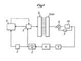
- a motor Ml which acts on a mobile element of an automaton is controlled by a human operator H under the direct control of its view V by means of a lever 2 with two opposite directions of movement.
- a clock 3 is triggered by lever 2 when a series of movements begins. This clock 3 is connected to a central unit 4 where a support is printed.
- the lever 2 is also connected to a variable frequency pulse generator 5 which is also connected to the central unit 4.
- the pulse generator 5 is also connected to a counter-down counter 6 whose outputs are combined with a 7 DAC digital to analog converter.
- the latter is connected to a position reference circuit 8 which is connected to the motor Ml directly and by a position detector 9.
- the orders given by means of the lever 2 are transmitted to the motor Ml via the generator 5 d ' frequency pulses variable at a predetermined frequency depending on the position of lever 2.
- the pulses are transmitted to it through the converter 7 DAC.
- the support is made up by recording therein the duration of operation of the clock 3 during each period during which the generator 5 delivers the same signal.
- the central unit 4 is connected, as indicated in broken lines, to the generator 5 to control it in accordance with the signals carried by the impressed support.
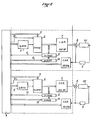
- Figure 2 shows real circuits in an automaton with two motors Ml, M2.
- the central unit 4 comprises a current microcomputer card with programmable clock available commercially under the reference INTEL SBC 80-24.
- the clock on this card plays the role of clock 3 and is used to determine the time between any modification of each component of the PLC speed vector.
- the outputs of the converter are monitored at a frequency of 10 ms, for example.
- the programmable frequency generator known commercially under the reference INTEL 8253 (1 ⁇ 3) can be adopted as the pulse generator.
- the totalizer is, in this example, 12 binary digits, known under the reference 3 x74193 T.T.L. It counts or it counts according to the binary element of sign mentioned above. This information is supplied to it from the central unit 4 by a line 10.
- the converter 7 DAC is of the type known under the reference DAC 80.
- an accelerated pace can be obtained by acting on the base clock of the programmable frequency generators.
- the value can be chosen by the operator in a range of speeds. The rehearsal pace can therefore be set and changed with ease.
- the circuits of FIG. 2 also include, for each motor M1, M2, a digital comparator 12 (with 12 binary elements for example), connected to the central unit 4 by a line 13, connected to the outputs of the totalizer 6 with the converter 7 CNA. You can use the TTL3 x7485 comparator.
- This comparator 12 is combined with a register 14 to 12 binary elements (for example an INTEL 2 x8282 register) which is also connected to the central unit 4.
- This register 14 can be preloaded from the central unit 4 to a value to which corresponds a predetermined position of the motor Ml or M2.
- the comparator 12 finds the same value between the totalizer 6 and the register 14, it sends to the central unit 4 a stop command.
Landscapes
- Physics & Mathematics (AREA)
- General Physics & Mathematics (AREA)
- Engineering & Computer Science (AREA)
- Automation & Control Theory (AREA)
- Control Of Stepping Motors (AREA)
- Control Of Electric Motors In General (AREA)
Applications Claiming Priority (2)
| Application Number | Priority Date | Filing Date | Title |
|---|---|---|---|
| FR8117388 | 1981-09-15 | ||
| FR8117388A FR2512979A1 (fr) | 1981-09-15 | 1981-09-15 | Procede et circuit pour la realisation d'un support impressionne et pour la commande d'un automate |
Publications (1)
| Publication Number | Publication Date |
|---|---|
| EP0074902A1 true EP0074902A1 (de) | 1983-03-23 |
Family
ID=9262151
Family Applications (1)
| Application Number | Title | Priority Date | Filing Date |
|---|---|---|---|
| EP82401653A Withdrawn EP0074902A1 (de) | 1981-09-15 | 1982-09-10 | Verfahren und Schaltung zur Erzeugung eines abgedruckten Trägers und zur Steuerung eines Automaten |
Country Status (3)
| Country | Link |
|---|---|
| EP (1) | EP0074902A1 (de) |
| DE (1) | DE74902T1 (de) |
| FR (1) | FR2512979A1 (de) |
Citations (1)
| Publication number | Priority date | Publication date | Assignee | Title |
|---|---|---|---|---|
| US3736580A (en) * | 1972-04-24 | 1973-05-29 | Tokyo Seimitisu Sokki Kk | Play back - machine control (position information storage and reproduction device) |
-
1981
- 1981-09-15 FR FR8117388A patent/FR2512979A1/fr active Granted
-
1982
- 1982-09-10 EP EP82401653A patent/EP0074902A1/de not_active Withdrawn
- 1982-09-10 DE DE1982401653 patent/DE74902T1/de active Pending
Patent Citations (1)
| Publication number | Priority date | Publication date | Assignee | Title |
|---|---|---|---|---|
| US3736580A (en) * | 1972-04-24 | 1973-05-29 | Tokyo Seimitisu Sokki Kk | Play back - machine control (position information storage and reproduction device) |
Also Published As
| Publication number | Publication date |
|---|---|
| FR2512979A1 (fr) | 1983-03-18 |
| FR2512979B1 (de) | 1983-12-23 |
| DE74902T1 (de) | 1983-08-18 |
Similar Documents
| Publication | Publication Date | Title |
|---|---|---|
| FR2513925A1 (fr) | Manipulateur pour deplacer le centre d'un outil d'element fonctionnel vers plusieurs positions | |
| CH617400A5 (de) | ||
| FR2474190A1 (fr) | Dispositif et procede de commande d'une machine comportant un outil d'usinage d'une piece | |
| FR2703620A1 (fr) | Système de commande multitâche pour un robot. | |
| CH639584A5 (fr) | Automate susceptible d'apprentissage. | |
| FR2548693A1 (fr) | Dispositif d'entrainement en rotation pour predelivreur-mesureur de trame, sur une machine a tisser sans navette | |
| FR2569681A1 (fr) | Systeme et procede de servocommande pour la fabrication de recipients en verre | |
| EP0011260A1 (de) | Verfahren zum Positionieren eines beweglichen Körpers | |
| EP0074902A1 (de) | Verfahren und Schaltung zur Erzeugung eines abgedruckten Trägers und zur Steuerung eines Automaten | |
| US3654613A (en) | Programmed manipulator apparatus with artificial end-of-program facilities | |
| FR2495797A1 (fr) | Systeme de pilotage automatique d'un vehicule terrestre autonome | |
| EP0114141A2 (de) | Verfahren zur automatischen Steuerung einer Schleifmaschine mit drehbarem Schleifkopf zum Schleifen von Glasplattenrändern und Vorrichtung zur Anwendung desselben | |
| FR2523901A1 (fr) | Machine de compostage automatisee et unite de compostage pour une telle machine | |
| EP0272959B1 (de) | Verfahren zur Wiedergabe einer aufgenommenen bewegenden Szene, insbesondere auf Videodisk, und seine Verwendung als Fahrsimulator | |
| FR2511629A1 (fr) | Systeme electrique de commande pour la limitation de la course sans butee sur des machines-outils, en particulier des machines a roder | |
| FR2515161A1 (fr) | Dispositif de mesure de course, notamment dispositif de mesure de hauteur pour des appareils elevateurs | |
| FR2694461A1 (fr) | Disposition permettant la commande d'un moteur d'alimentation en feuilles utilisé dans une imprimante. | |
| FR2509600A1 (fr) | Installation de radiodiagnostic pour des radiographies en couches | |
| FR2503971A1 (fr) | Appareil d'enregistrement et de reproduction d'un signal video | |
| FR2386886A1 (fr) | Appareil pour la commande de la vitesse d'une bande, en particulier, d'une bande magnetique pour cassette | |
| EP1559816A2 (de) | Fachbildungsvorrichtung, Webmaschine mit einer solchen Vorrichtung und durch diese Vorrichtung ausgeführtes Verfahren | |
| FR2547085A1 (fr) | Procede et dispositif pour l'execution d'operations d'entree de parametres et de sortie de parametres a l'aide des moyens d'affichage et d'enregistrement d'un enregistreur de route | |
| GB2030727A (en) | Bridge crane control | |
| EP0102277B1 (de) | Bearbeitungsvorrichtung bei kontinuierlichem Bewegungsablauf mit dimensionaler Steuerung | |
| FR2507841A1 (fr) | Procede pour amortir les oscillations d'un moteur pas a pas |
Legal Events
| Date | Code | Title | Description |
|---|---|---|---|
| PUAI | Public reference made under article 153(3) epc to a published international application that has entered the european phase |
Free format text: ORIGINAL CODE: 0009012 |
|
| 17P | Request for examination filed |
Effective date: 19820917 |
|
| AK | Designated contracting states |
Designated state(s): AT BE CH DE GB IT LI LU NL SE |
|
| ITCL | It: translation for ep claims filed |
Representative=s name: BARZANO' E ZANARDO MILANO S.P.A. |
|
| TCNL | Nl: translation of patent claims filed | ||
| TCAT | At: translation of patent claims filed | ||
| DET | De: translation of patent claims | ||
| STAA | Information on the status of an ep patent application or granted ep patent |
Free format text: STATUS: THE APPLICATION IS DEEMED TO BE WITHDRAWN |
|
| 18D | Application deemed to be withdrawn |
Effective date: 19851120 |
|
| RIN1 | Information on inventor provided before grant (corrected) |
Inventor name: BERLAND, RICHARD Inventor name: ROUX, SERGE |