EP0074801A1 - Chauffe-eau - Google Patents
Chauffe-eau Download PDFInfo
- Publication number
- EP0074801A1 EP0074801A1 EP82304736A EP82304736A EP0074801A1 EP 0074801 A1 EP0074801 A1 EP 0074801A1 EP 82304736 A EP82304736 A EP 82304736A EP 82304736 A EP82304736 A EP 82304736A EP 0074801 A1 EP0074801 A1 EP 0074801A1
- Authority
- EP
- European Patent Office
- Prior art keywords
- heater
- water
- heating unit
- printed circuit
- temperature
- Prior art date
- Legal status (The legal status is an assumption and is not a legal conclusion. Google has not performed a legal analysis and makes no representation as to the accuracy of the status listed.)
- Granted
Links
- XLYOFNOQVPJJNP-UHFFFAOYSA-N water Substances O XLYOFNOQVPJJNP-UHFFFAOYSA-N 0.000 title claims abstract description 83
- 238000010438 heat treatment Methods 0.000 title claims abstract description 68
- 239000011159 matrix material Substances 0.000 claims description 12
- 230000001105 regulatory effect Effects 0.000 claims description 4
- 239000007787 solid Substances 0.000 claims description 2
- 230000003247 decreasing effect Effects 0.000 claims 1
- 229910052751 metal Inorganic materials 0.000 abstract description 3
- 239000002184 metal Substances 0.000 abstract description 3
- 238000010276 construction Methods 0.000 description 3
- 230000000712 assembly Effects 0.000 description 2
- 238000000429 assembly Methods 0.000 description 2
- 235000014443 Pyrus communis Nutrition 0.000 description 1
- 239000004411 aluminium Substances 0.000 description 1
- 229910052782 aluminium Inorganic materials 0.000 description 1
- XAGFODPZIPBFFR-UHFFFAOYSA-N aluminium Chemical compound [Al] XAGFODPZIPBFFR-UHFFFAOYSA-N 0.000 description 1
- 239000010425 asbestos Substances 0.000 description 1
- 238000006243 chemical reaction Methods 0.000 description 1
- 230000001276 controlling effect Effects 0.000 description 1
- 238000001816 cooling Methods 0.000 description 1
- 238000010586 diagram Methods 0.000 description 1
- 239000011521 glass Substances 0.000 description 1
- 239000008236 heating water Substances 0.000 description 1
- 238000007654 immersion Methods 0.000 description 1
- 239000012774 insulation material Substances 0.000 description 1
- 238000000034 method Methods 0.000 description 1
- 238000012544 monitoring process Methods 0.000 description 1
- 229910052895 riebeckite Inorganic materials 0.000 description 1
- 238000011144 upstream manufacturing Methods 0.000 description 1
- 238000003466 welding Methods 0.000 description 1
Images


Classifications
-
- F—MECHANICAL ENGINEERING; LIGHTING; HEATING; WEAPONS; BLASTING
- F24—HEATING; RANGES; VENTILATING
- F24H—FLUID HEATERS, e.g. WATER OR AIR HEATERS, HAVING HEAT-GENERATING MEANS, e.g. HEAT PUMPS, IN GENERAL
- F24H1/00—Water heaters, e.g. boilers, continuous-flow heaters or water-storage heaters
- F24H1/10—Continuous-flow heaters, i.e. heaters in which heat is generated only while the water is flowing, e.g. with direct contact of the water with the heating medium
- F24H1/101—Continuous-flow heaters, i.e. heaters in which heat is generated only while the water is flowing, e.g. with direct contact of the water with the heating medium using electric energy supply
- F24H1/102—Continuous-flow heaters, i.e. heaters in which heat is generated only while the water is flowing, e.g. with direct contact of the water with the heating medium using electric energy supply with resistance
-
- F—MECHANICAL ENGINEERING; LIGHTING; HEATING; WEAPONS; BLASTING
- F24—HEATING; RANGES; VENTILATING
- F24H—FLUID HEATERS, e.g. WATER OR AIR HEATERS, HAVING HEAT-GENERATING MEANS, e.g. HEAT PUMPS, IN GENERAL
- F24H15/00—Control of fluid heaters
- F24H15/20—Control of fluid heaters characterised by control inputs
- F24H15/212—Temperature of the water
-
- F—MECHANICAL ENGINEERING; LIGHTING; HEATING; WEAPONS; BLASTING
- F24—HEATING; RANGES; VENTILATING
- F24H—FLUID HEATERS, e.g. WATER OR AIR HEATERS, HAVING HEAT-GENERATING MEANS, e.g. HEAT PUMPS, IN GENERAL
- F24H15/00—Control of fluid heaters
- F24H15/30—Control of fluid heaters characterised by control outputs; characterised by the components to be controlled
- F24H15/355—Control of heat-generating means in heaters
- F24H15/37—Control of heat-generating means in heaters of electric heaters
-
- F—MECHANICAL ENGINEERING; LIGHTING; HEATING; WEAPONS; BLASTING
- F24—HEATING; RANGES; VENTILATING
- F24H—FLUID HEATERS, e.g. WATER OR AIR HEATERS, HAVING HEAT-GENERATING MEANS, e.g. HEAT PUMPS, IN GENERAL
- F24H9/00—Details
- F24H9/20—Arrangement or mounting of control or safety devices
- F24H9/2007—Arrangement or mounting of control or safety devices for water heaters
- F24H9/2014—Arrangement or mounting of control or safety devices for water heaters using electrical energy supply
-
- H—ELECTRICITY
- H05—ELECTRIC TECHNIQUES NOT OTHERWISE PROVIDED FOR
- H05B—ELECTRIC HEATING; ELECTRIC LIGHT SOURCES NOT OTHERWISE PROVIDED FOR; CIRCUIT ARRANGEMENTS FOR ELECTRIC LIGHT SOURCES, IN GENERAL
- H05B3/00—Ohmic-resistance heating
- H05B3/10—Heater elements characterised by the composition or nature of the materials or by the arrangement of the conductor
Definitions
- This invention relates to apparatus for heating water for domestic or commercial purposes and being provided with a supply of water, for example, cold water under pressure from a water main.
- Hot water supplies are usually provided from a tank or other storage container, in which there is heating means such as an electrical immersion heater or a coil through which hot water heated by a boiler is circulated. Heat exchange by such methods is relatively slow and inefficient, due to gassification, i.e. water bubbles adhering to the heater element, and also the storage of the hot water is wasteful.
- heating means such as an electrical immersion heater or a coil through which hot water heated by a boiler is circulated.
- Heat exchange by such methods is relatively slow and inefficient, due to gassification, i.e. water bubbles adhering to the heater element, and also the storage of the hot water is wasteful.
- water heating apparatus comprising an inlet duct, an outlet duct, and a water heating unit between the inlet and outlet ducts, the heating unit including a printed circuit heater means.
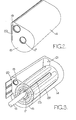
- this shows a water heating apparatus for use for example in a domestic situation for providing a supply of hot water and being supplied from a cold water main supply.
- the apparatus as shown in Figure 1 includes an inlet section 10 and an outlet section 11 and a body section 12, containing the heating means of the appliance, situated between the inlet and outlet sections. Part of the casing has been removed for clarity and it is to be understood that the external shape of the apparatus may take any other form instead of the generally rectangular configuration shdwn.
- the body section 12 can also be other than rectangular,for example it can be of pear-shaped cross-section, as shown in Figures 2 and 3.
- control 13 On the inlet section 10 there can be mounted a control 13 by means of which the temperature of the water delivered can be regulated, as will be described.
- Figures 2 to 5 show the construction and arrangement of various parts of a first embodiment of water heating apparatus, to fit into a casing in the form of Figure 1 or in any suitable alternative form.
- Figures 2 and 3 show a metallic body 14 of generally pear shape in transverse cross-section.
- the body has end walls 15, 16 respectively and in the end wall 15, which is the inlet end of the body, .there is provided a generally central hole 17.
- the hole 17 is threaded to receive an adaptor plug supporting a cold water inlet pipe 18 which, in use, is arranged to receive pressurised cold or relatively cold water from, for example, the main supply. If required the inlet could incorporate a non-return valve.
- the wall 15 also contains a further threaded hole 19, which is plugged, in use, and a slot 20.
- the end wall 16 has a hole 21, longitudinally aligned with the hole 19, and which is threaded like the hole 17, to receive an adaptor plug 23 ( Figures 6 and 7), similar to that fitted in the hole 17, and carrying an outlet pipe 24.
- the inlet pipe 18 extends to the interior surface of the end wall 16 where it is closed. However the pipe 18 has an axially extending slot 25 in its surface to allow the cold water to flow therefrom into a spirally arranged heater unit 26 shown in Figure 3.
- the heater unit shown best in Figures 4 and 5, is in the form of an electrical printed circuit heater 27 sandwiched between a pair of metal plates and rolled into a spiral. Connections 28 for supplying power to and for controlling the heater are provided on a longitudinal extension part at one corner 29 of the heater unit which protrudes through the slot 20. A glass or metal laminate, i.e. aluminium can be provided around the outside of the heater unit.
- the heater unit is a spiral, in this example of four turns, means that the surface area of the heater unit contacted by the water, as well as the contact time is significantly increased as compared to conventional heater units such as heating coils. This increases the efficiency of the heater, whilst enabling it to be kept relatively short and compact, thus allowing the water heating apparatus itself to be made compactly and less expensively. It has also been found that this construction of heater substantially reduces gassification, further improving the heating -ef$ciency.
- Figure 6 shows a first example of an assembled body 14, inlet and outlet pipes 18, 24 heater unit 26 and associated controls for water heating apparatus of the invention.
- a casing 30 is shown schematically around the body 14, and this can contain asbestos or the like as heat insulation material.
- Electrical connection lines 31, 32 are taken from a power supply (to be described in Figure 10) to the connections 28 on the corner extension 29 of the heater unit.
- An override or cut-out sensor 33 is fitted on the body 14 to monitor the temperature of the water entering the outlet pipe 24 and to operate if a predetermined maximum value is exceeded. For example it could operate to switch off the heater unit and could be manually or automatically reset.
- Electrical lines 34, 35 connect the sensor to a control circuit, not shown.
- Figure 7 shows a similar arrangement to figure 6, but with an increased number of printed circuit heaters, giving six contacts 36 and associated supply lines 37.
- an override sensor 38 similar to the sensor 33 in Figure 6, there are additional sensors 39, 40 in the inlet and outlet pipes 18, 24 respectively, to provide electrical signals related to the temperature of water flowing therein.
- Each sensor has a pair of electrical connection lines leading therefrom to the control means of the water heating apparatus, which will be described below.
- a small heater unit such as that shown in Figure 6 will be used in a 5kw water heating apparatus and a multi-circuit arrangement such as in Figure 7 would produce 10kw.
- Figure 8 shows the use of three body assemblies of Figure 6 connected in series, so that each one can perform a stage of the water heating operation.
- the inlet pipe 18 of the first body assembly is fed from the cold water supply and after being heated by passing around the spiral heating unit in the body, the water passes out through the outlet pipe 24 of said first body, which also serves as the inlet pipe to the next body downstream in the series, and so on for the third and any subsequent body assemblies, as the number is not limited to the three shown.
- This arrangement reduces the wear on each heater unit and thus prolongs the life thereof.
- Each body assembly is shown as in Figure 6, but with a water temperature sensor 41, and although not shown each body assembly can also be provided with an override sensor.
- a heater control unit 42 and a temperature control unit 43 are also shown, along with a water outlet distribution system of five outlet branches 44 for the heated water to be taken off.
- the temperature sensors monitor water temperature along the whole body assembly and can detect hot or cold spots, for example, to cut out the heater in one particular section thereof.
- each assembly can raise the water temperature by a given amount so that the heating load is spread over three heater units to produce water of the required temperature at the outlet of the end assembly. If required the bodies could be as in Figure 7.
- Figure 9 shows an arrangement where the temperature sensor 44 is produced together with the heating elements 45 in the printed circuit board of the heater unit.
- This is a particularly compact arrangement allowing connections 46 to be made to the heater control unit 47 and connections 48 to the temperature control unit 49 at the board edge, thereby dispensing with an external, separate temperature sensor, like the sensor 41 in Figure 8.
- the sensor 44 monitors water temperature along the whole of the heater unit and can cut out a heating section if a hot spot is detected.
- Figure 10 shows an electrical control circuit suitable for all the water heating arrangements shown in Figures 1 to 9, where the heating apparatus has associated temperature sensing.
- a spiral heater unit is denoted by the numeral 50 and sensors for monitoring inlet and outlet water temperature are denoted by the numerals 39 and 40, as for Figure 7, in the inlet and outlet sections 10 and 11.
- the heater unit is controlled through a solid state switch or relay 51. This is provided with a mains electrical supply at 52. If a relay is used, it can be of any suitable type, for example incorporating a triac value.
- the sensors 39, 40 are connected in a bridge circuit 53 which is variable at 54 to regulate the heater unit output. This variation is carried out by way of the control knob 13 of Figure 1.
- a 24 volt power supply is connected between lines 55 and 56 with the voltage being supplied to the switch or relay 51.
- the line 55 is continued to the variable adjustment means 54 of the bridge circuit 53, whilst the line 56 is connected to the opposite point of the circuit 53.
- a line 57 extends from a further junction of the bridge circuit between the connection of the sensor 39 and a resistor to one input of an operational amplifier 58. This is a (temperature) difference amplifier.
- a line 59 extends from the remaining junction of the circuit 53 to another input of the amplifier 58.
- An output line 60 from the amplifier is connected to the line 56 of zero voltage, through resistors 61 and 62. Connected between the lines 59 and 60 is a coil 63.
- a line 63 extends from the switch or relay 51 to join the line 60 between the resistors 61, 62. It has a diode 64 connected in it between collector and base and a line 65 from the emitter of the diode 64 extends to the base of another diode 66, whose collector and emitter are in a line 67 between lines 56 and 63. A further resistor 68 is connected between the lines 56 and 65 to complete the circuit.
- the arrangement is such that the inlet and outlet temperatures are sensed by senors 39, 40 and according to the setting of the control knob 13 at variable adjustment 54, the heater current is regulated to maintain the chosen output temperature despite changes in input temperature.
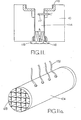
- FIGs 11, 11a and 11b show inlet and outlet sections and an alternative form of heater unit for use in water heating apparatus in the form shown in Figure 1.
- the inlet section 10 shown in Figure 11 includes a central water duct 114.
- an adaptor 115 for attachment to associated pipework i and this also incorporates a non-return valve indicated generally at 116.
- the non-return valve may take any conventional form.
- Extending into the duct 114 in the inlet section is an electrical temperature sensor device 117 which is capable of providing an electrical signal related to the temperature of the water flowing through the inlet duct.
- casings containing the electrical supply and control equipment can be of the&rms already described.
- the provision of these around the inlet duct provides for the cold water flowing therethrough cooling for the electrical and electronic equipment.
- the outlet section 11 also has a central duct 119 through which the heated water flows.
- an adaptor 120 for connection to associated pipework and there is also an electrical temperature sensor 121 which extends into the duct 119.
- an electrical temperature sensor 121 which extends into the duct 119.
- a temperature responsive switch 123 Situated close to the duct 119 is a temperature responsive switch 123. Like the sensors 33 and 38 already described, this is arranged to operate in the event that the temperature in the outlet duct 119 exceeds a predetermined maximum value. It is arranged to be manually reset when it has been actuated in the event of excess temperature conditions.
- the body section 12 can be in the form of a rectangular cowling, and within this is a cylindrical heating unit 124 shown in Figure 11a. This has screw threaded ends to engage in the adaptors 118 and 122 in the inlet and outlet sections 10 and 11.
- a matrix indicated at 125 made up from a number of printed circuit boards each with printed electrical heater circuits on their respective surfaces. The matrix is made up from a number of boards arranged perpendicularly to one another so as to define a number of square or rectangular through flow passages for water each passage being bordered by the heating elements printed on the circuit boards.
- the matrix is made up from a number of flat boards with slits which enable inter-engagement between the boards in a rigid manner. Electrical connections between them are either at the ends or at any convenient place within the matrix.
- External connections of which there are four shown at 126 provide electrical supply to the printed circuit boards.
- the apparatus therefore operates with water flowing through the inlet duct 114 of the inlet section 10 and through the matrix 125 to be heated as it passes through this unit.
- the water having been heated then flows out through the outlet duct 119. Heating of the water occurs only when there is a demand and there is therefore no necessity for storage of heated water.
- Figure 12 shows a further alternative heater unit having a number of parallel printed circuit board plates 134. Each is rectangular and they are mounted apart by support columns 135. Such a unit would be enclosed within a surrounding cowling and electrical connections can be made at the edges of the plates.
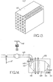
- Figure 13 shows an alternative matrix form of heater unit at 137 of generally rectangular configuration instead of the cylindrical form shown in Figure 11a. It is however constructed in similar manner. Part is broken away for clarity to show the heating elements.
- Figure 14 shows an alternative heating apparatus which includes a casing 138 containing a hollow body 139.
- An inlet pipe 140 and an outlet pipe 141 are connected to opposite ends of the body 139 and within it are a pair of printed circuit board heater plates 142 having provision for electrical connection of their opposite ends outside the body 139. These may be arranged to provide disturbance to the fbw of water through the body so that maximum heat exchange takes place from the heaters to the water.
- the inlet and outlet pipes 140, 141 include respective temperature sensors 143, 144 connected in control circuits in the manner already described.
- the inlet pipe 140 is connected to pipework 145 which includes a mannual valve 146 for interrupting the supply and a solenoid operated valve 147 upstream of the manual valve.
- the solenoid valve is connected in the control circuit to regulate the supply according to the load and output temperature requirements.
- Figures 15 and 16 shows a further form of water heating apparatus which might be used in a commercial environment.
- a number of alternative sections are shown of which two or more may be used in combination, or each can be used individually as required.
- Inlet and outlet sections are omitted and there is shown only the heating unit which, in this example, has four sections.
- the first section 148 has a tubular printed circuit board heater 149 being flared towards the inlet end.
- Figure 16 shows the circular section of this.
- the printed heater elements are shown as a coil on the printed circuit board and electrical connections to opposite ends of this are indicated at 150.
- heater unit 151 A similar but cylindrical form of heater unit 151 is shown in the section 152 at the opposite end of the appliance. Electrical connections to this are indicated at 153.
- the section 154 has two parallel cylindrical units each formed as a printed circuit board 155, 156. Respective electrical connections are indicated at 157, 158.
- the further form shown in the section 159 has three parallel cylindrical units 160, 161, 162 with respective electrical connections 163, 164, 165.
- heaters can be used each incorporating printed circuit boards. These may be insulated or exposed directly to the water in which case adequate earthing is necessary.
- spiral arrangement is most advantageous, since in addition to its efficiency advantages and lower cost, it simplies electrical connections thereto because they can be made at any convenient place.
Priority Applications (1)
| Application Number | Priority Date | Filing Date | Title |
|---|---|---|---|
| AT82304736T ATE14625T1 (de) | 1981-09-10 | 1982-09-09 | Wassererhitzer. |
Applications Claiming Priority (2)
| Application Number | Priority Date | Filing Date | Title |
|---|---|---|---|
| GB8127379 | 1981-09-10 | ||
| GB8127379 | 1981-09-10 |
Publications (2)
| Publication Number | Publication Date |
|---|---|
| EP0074801A1 true EP0074801A1 (fr) | 1983-03-23 |
| EP0074801B1 EP0074801B1 (fr) | 1985-07-31 |
Family
ID=10524421
Family Applications (1)
| Application Number | Title | Priority Date | Filing Date |
|---|---|---|---|
| EP82304736A Expired EP0074801B1 (fr) | 1981-09-10 | 1982-09-09 | Chauffe-eau |
Country Status (6)
| Country | Link |
|---|---|
| EP (1) | EP0074801B1 (fr) |
| JP (1) | JPS58501635A (fr) |
| AT (1) | ATE14625T1 (fr) |
| DE (1) | DE3265084D1 (fr) |
| GB (1) | GB2109516B (fr) |
| WO (1) | WO1983000915A1 (fr) |
Cited By (1)
| Publication number | Priority date | Publication date | Assignee | Title |
|---|---|---|---|---|
| CN103398463A (zh) * | 2013-04-28 | 2013-11-20 | 浙江西德斯电气有限公司 | 储水速热即热式电热水器 |
Families Citing this family (5)
| Publication number | Priority date | Publication date | Assignee | Title |
|---|---|---|---|---|
| US4529866A (en) * | 1983-03-11 | 1985-07-16 | Raychem Corporation | Method and apparatus for electrically heating diesel fuel |
| GB8520675D0 (en) * | 1985-08-19 | 1985-09-25 | Leung T B K | Thermoelectric water supplier |
| GB9024419D0 (en) * | 1990-11-09 | 1991-01-02 | Ist Lab Ltd | Heating apparatus |
| GB9706550D0 (en) * | 1997-04-01 | 1997-05-21 | Caradon Mira Ltd | Improvements in or relating to electric water heaters |
| GB2487431B (en) * | 2011-01-22 | 2016-07-13 | Applied Energy Products Ltd | Improvements in water heating |
Citations (5)
| Publication number | Priority date | Publication date | Assignee | Title |
|---|---|---|---|---|
| DE2240186A1 (de) * | 1972-08-16 | 1974-02-21 | Stiebel Eltron Gmbh & Co Kg | Heizflansch fuer elektrisch beheizte heisswasserbereitungsgeraete |
| US3885125A (en) * | 1970-10-05 | 1975-05-20 | Fulton Boiler Works | Method for electrically heating a heat transfer fluid |
| DE2327941B2 (de) * | 1973-06-01 | 1975-12-11 | Licentia Patent-Verwaltungs-Gmbh, 6000 Frankfurt | Elektrisch beheizter Durchlauferhitzer |
| US4093847A (en) * | 1974-09-10 | 1978-06-06 | Datametrics Corporation | Temperature control system for electric fluid heater |
| US4185187A (en) * | 1977-08-17 | 1980-01-22 | Rogers David H | Electric water heating apparatus |
-
1982
- 1982-09-09 EP EP82304736A patent/EP0074801B1/fr not_active Expired
- 1982-09-09 GB GB08225734A patent/GB2109516B/en not_active Expired
- 1982-09-09 DE DE8282304736T patent/DE3265084D1/de not_active Expired
- 1982-09-09 AT AT82304736T patent/ATE14625T1/de not_active IP Right Cessation
- 1982-09-09 JP JP57502686A patent/JPS58501635A/ja active Pending
- 1982-09-09 WO PCT/GB1982/000267 patent/WO1983000915A1/fr unknown
Patent Citations (5)
| Publication number | Priority date | Publication date | Assignee | Title |
|---|---|---|---|---|
| US3885125A (en) * | 1970-10-05 | 1975-05-20 | Fulton Boiler Works | Method for electrically heating a heat transfer fluid |
| DE2240186A1 (de) * | 1972-08-16 | 1974-02-21 | Stiebel Eltron Gmbh & Co Kg | Heizflansch fuer elektrisch beheizte heisswasserbereitungsgeraete |
| DE2327941B2 (de) * | 1973-06-01 | 1975-12-11 | Licentia Patent-Verwaltungs-Gmbh, 6000 Frankfurt | Elektrisch beheizter Durchlauferhitzer |
| US4093847A (en) * | 1974-09-10 | 1978-06-06 | Datametrics Corporation | Temperature control system for electric fluid heater |
| US4185187A (en) * | 1977-08-17 | 1980-01-22 | Rogers David H | Electric water heating apparatus |
Cited By (2)
| Publication number | Priority date | Publication date | Assignee | Title |
|---|---|---|---|---|
| CN103398463A (zh) * | 2013-04-28 | 2013-11-20 | 浙江西德斯电气有限公司 | 储水速热即热式电热水器 |
| CN103398463B (zh) * | 2013-04-28 | 2014-06-11 | 浙江西德斯电气有限公司 | 储水速热即热式电热水器 |
Also Published As
| Publication number | Publication date |
|---|---|
| EP0074801B1 (fr) | 1985-07-31 |
| GB2109516A (en) | 1983-06-02 |
| DE3265084D1 (en) | 1985-09-05 |
| WO1983000915A1 (fr) | 1983-03-17 |
| GB2109516B (en) | 1985-02-13 |
| ATE14625T1 (de) | 1985-08-15 |
| JPS58501635A (ja) | 1983-09-29 |
Similar Documents
| Publication | Publication Date | Title |
|---|---|---|
| US4604515A (en) | Tankless electric water heater with staged heating element energization | |
| US4567350A (en) | Compact high flow rate electric instantaneous water heater | |
| US5408578A (en) | Tankless water heater assembly | |
| US4146775A (en) | Automatic control system for an electrode-type air humidifier | |
| US4341936A (en) | Electromagnetic induction energy converter | |
| US4859834A (en) | Power controller for heat tracing cable which responds to ambient temperature | |
| US6943325B2 (en) | Water heater | |
| US3446939A (en) | Electric immersion water heater | |
| US4503305A (en) | Electromagnetic induction air heater | |
| EP0074801A1 (fr) | Chauffe-eau | |
| JP2724473B2 (ja) | 電気制御式給水器 | |
| CA2198424C (fr) | Appareil pour chauffer les pieces d'un immeuble a l'aide d'un tube a eau chaude electrique et methode appropriee | |
| GB2202619A (en) | Electric heating systems | |
| EP0143993A1 (fr) | Système de commande | |
| GB2140990A (en) | Water heaters | |
| US20090159259A1 (en) | Modular heat pump liquid heater system | |
| EP0178351B1 (fr) | Chauffe-eau, par exemple chaudière d'eau sanitaire | |
| US2987604A (en) | Water heaters | |
| US4321456A (en) | Electrical hot air appliance | |
| US4483388A (en) | Apparatus and method for providing failsafe supplemental heat _regulation in an air conditioning control | |
| JP2022140401A (ja) | 領域内の可変電力出力を有する加熱バンドル | |
| GB2265445A (en) | Water heater | |
| JPS62168359A (ja) | 連続加熱器 | |
| GB2181218A (en) | Central heating apparatus | |
| WO1989007740A1 (fr) | Systeme de commande de chaudiere electrique |
Legal Events
| Date | Code | Title | Description |
|---|---|---|---|
| PUAI | Public reference made under article 153(3) epc to a published international application that has entered the european phase |
Free format text: ORIGINAL CODE: 0009012 |
|
| AK | Designated contracting states |
Designated state(s): AT BE CH DE FR IT LI LU NL SE |
|
| 17P | Request for examination filed |
Effective date: 19830915 |
|
| ITF | It: translation for a ep patent filed |
Owner name: BUGNION S.P.A. |
|
| GRAA | (expected) grant |
Free format text: ORIGINAL CODE: 0009210 |
|
| AK | Designated contracting states |
Designated state(s): AT BE CH DE FR IT LI LU NL SE |
|
| REF | Corresponds to: |
Ref document number: 14625 Country of ref document: AT Date of ref document: 19850815 Kind code of ref document: T |
|
| REF | Corresponds to: |
Ref document number: 3265084 Country of ref document: DE Date of ref document: 19850905 |
|
| PG25 | Lapsed in a contracting state [announced via postgrant information from national office to epo] |
Ref country code: AT Effective date: 19850909 |
|
| PG25 | Lapsed in a contracting state [announced via postgrant information from national office to epo] |
Ref country code: SE Effective date: 19850910 |
|
| ET | Fr: translation filed | ||
| PG25 | Lapsed in a contracting state [announced via postgrant information from national office to epo] |
Ref country code: LU Free format text: LAPSE BECAUSE OF NON-PAYMENT OF DUE FEES Effective date: 19850930 Ref country code: LI Effective date: 19850930 Ref country code: CH Effective date: 19850930 Ref country code: BE Effective date: 19850930 |
|
| BERE | Be: lapsed |
Owner name: OVERSEAS AUTOMATION LTD Effective date: 19850909 |
|
| PG25 | Lapsed in a contracting state [announced via postgrant information from national office to epo] |
Ref country code: NL Effective date: 19860401 |
|
| NLV4 | Nl: lapsed or anulled due to non-payment of the annual fee | ||
| PG25 | Lapsed in a contracting state [announced via postgrant information from national office to epo] |
Ref country code: FR Free format text: LAPSE BECAUSE OF NON-PAYMENT OF DUE FEES Effective date: 19860530 |
|
| REG | Reference to a national code |
Ref country code: CH Ref legal event code: PL |
|
| PG25 | Lapsed in a contracting state [announced via postgrant information from national office to epo] |
Ref country code: DE Effective date: 19860603 |
|
| PLBE | No opposition filed within time limit |
Free format text: ORIGINAL CODE: 0009261 |
|
| STAA | Information on the status of an ep patent application or granted ep patent |
Free format text: STATUS: NO OPPOSITION FILED WITHIN TIME LIMIT |
|
| 26N | No opposition filed | ||
| REG | Reference to a national code |
Ref country code: FR Ref legal event code: ST |
|
| EUG | Se: european patent has lapsed |
Ref document number: 82304736.0 Effective date: 19860729 |