EP0074311A1 - Guide d'onde rectangulaire à fentes rayonnantes et à large bande de fréquence - Google Patents
Guide d'onde rectangulaire à fentes rayonnantes et à large bande de fréquence Download PDFInfo
- Publication number
- EP0074311A1 EP0074311A1 EP82401593A EP82401593A EP0074311A1 EP 0074311 A1 EP0074311 A1 EP 0074311A1 EP 82401593 A EP82401593 A EP 82401593A EP 82401593 A EP82401593 A EP 82401593A EP 0074311 A1 EP0074311 A1 EP 0074311A1
- Authority
- EP
- European Patent Office
- Prior art keywords
- guide
- slots
- wave guide
- current lines
- waveguide
- Prior art date
- Legal status (The legal status is an assumption and is not a legal conclusion. Google has not performed a legal analysis and makes no representation as to the accuracy of the status listed.)
- Withdrawn
Links
- 230000005855 radiation Effects 0.000 claims abstract description 13
- 229910003460 diamond Inorganic materials 0.000 claims description 3
- 239000010432 diamond Substances 0.000 claims description 3
- 230000008878 coupling Effects 0.000 description 9
- 238000010168 coupling process Methods 0.000 description 9
- 238000005859 coupling reaction Methods 0.000 description 9
- 230000001902 propagating effect Effects 0.000 description 2
- 238000005388 cross polarization Methods 0.000 description 1
- 238000010586 diagram Methods 0.000 description 1
- 239000003989 dielectric material Substances 0.000 description 1
- 230000005284 excitation Effects 0.000 description 1
- 238000005286 illumination Methods 0.000 description 1
- 230000010287 polarization Effects 0.000 description 1
- 238000007789 sealing Methods 0.000 description 1
- 230000035945 sensitivity Effects 0.000 description 1
Images

Classifications
-
- H—ELECTRICITY
- H01—ELECTRIC ELEMENTS
- H01Q—ANTENNAS, i.e. RADIO AERIALS
- H01Q21/00—Antenna arrays or systems
- H01Q21/0006—Particular feeding systems
- H01Q21/0037—Particular feeding systems linear waveguide fed arrays
- H01Q21/0043—Slotted waveguides
Definitions
- the present invention relates to a rectangular waveguide with direct radiation slots and a wide frequency band.
- a slit radiates power when it cuts current lines. Indeed, being able to be assimilated to an impedance Z placed in series on the current lines, there appears a potential difference between the walls of the slot, therefore radiation towards the outside.
- the field radiated by a slit is of the same nature as that radiated by a dipole of the same width, their respective polarizations being perpendicular.
- the power radiated by the slit being proportional to the square of the current flowing through it, one can then adjust the coupling of the slit with the guide by choosing its position and its inclination.
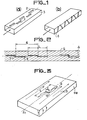
- the slots 1 can be arranged, as shown in FIG. 1a, longitudinally on the long side 2 of the guide 3, more or less eccentrically, or alternatively arranged transversely on the short side 4 of the guide, more or less inclined, as shown in Figure lb.
- these slots have the drawback of having conductances which vary rapidly as a function of frequency, consequently causing a variation in the coupling of the slots with the guide and a instability of the law of illumination which governs the radiated diagram and particularly the lateral lobes.
- the object of the present invention is to produce a rectangular waveguide with direct radiation slits which also has the advantage of operating over a wide frequency band.
- the rectangular waveguide with direct radiation slots according to the invention is such that each of these radiating slots, of length L close to the operating wavelength (X) of the guide, is placed on one side of the guide parallel to the current lines running along this side and has a recess made in its central part perpendicular to the current lines.
- the slots are formed on a large or a small side of the waveguide.
- these slits have the disadvantage of having a conductance which varies rapidly as a function of frequency, therefore preventing the guide from operating in a wide frequency band. .
- a radiating antenna produced from new radiating elements, in particular slots according to the invention must be such that each element must have a radiation admittance, and in particular a conductance which is in the active part, stable in frequency function.
- the excitation element of each slot is adapted to the admittance of the latter and that the coupling member of this element of the guide avoids, as far as possible, any additional mismatch other than that necessarily due to the radiation itself from the slit.
- FIG. 2 The three conditions are satisfied in the rectangular waveguide with radiating slits and with wide band according to the invention, represented in top view by FIG. 2.
- Each slot 5 of the guide 6 is a whole wave slot, relatively wide - if necessary enlarged into a double diamond - and has a recess 7 in its central part, recess produced perpendicular to the longitudinal axis ⁇ of the slot. It is known that a whole wave dipole, excited in its center - especially if its strands are relatively wide - has a high input impedance and more stable in frequency than a half-wave dipole. Also, according to the Babinet principle mentioned before, we can say that a whole-wave slit excited in its center has an admittance provided with the same properties, that is, a low input impedance, stable in frequency.
- the slit may have a length L slightly less than the operating wavelength (0.7 to 0.9 ⁇ ) if the slit is widened, for example in double diamond shape because the second resonance is then obtained for a slightly shorter length at ⁇ . This phenomenon will be further improved if the slot is covered or filled with a dielectric material for reasons of protection or sealing.
- the distance d separating the center of two successive slots 5 is close to the operating wavelength X of the guide.
- FIGS. 3 and 4 Two particular cases of embodiment are envisaged and shown in FIGS. 3 and 4.
- the widened slots 8 in double rhombus and arranged longitudinally, that is to say along the longitudinal axis ⁇ 1 of the long side 9.
- the slots are parallel to the current lines, except at the level of their recess 10 which cuts them.
- Each slit is not excited over its entire length L but only at its center which is the point where its radiation impedance is precisely stable in frequency.
- the dimension 1 of the step 10, which is perpendicular to the longitudinal axis ⁇ 1 of the long side of the guide, determines the coupling coefficient of the slot.
- the recess 10 placed in the center of the slot serves as an element for exciting the slot and for coupling to the feed guide.
- the second particular embodiment shown in FIG. 4 relates to a waveguide 15, the slots 16 of which are placed on a short side 17 of this guide, transversely, that is to say perpendicular to the longitudinal axis ⁇ 2 of the guide 15.
- the slots 16 are made parallel to the current lines propagating on this short side 17 of the guide, with a recess 18 located in their central part, this recess then cutting the current lines, as has been explained before.
- a conventional slot 19 is placed between each slot 16, parallel to them and not excited since they do not cut the current lines, thus playing the role of reflector.
- the distance between two excited slots 16 is close to wavelength 1 and the offset 18 of all these slots 16 is in the same direction in order to avoid radiation in cross-polarization with alternating phases which can alter the quality of the radiation of the slotted guide.
- Such a slotted waveguide which moreover has a fairly. high directivity, allows direct radiation of a horizontally polarized wave, avoiding the use of a polarizer to transform a vertically polarized wave.
- a waveguide such as that described in FIG. 4, can be produced, the cross section of which is almost square, with a side slightly less than the operating wavelength, and vertically polarized.
- FIG. 5 represents an embodiment of a slotted guide 11, of the same type as that described in FIG. 3 but having an improvement due to the particular shape of the wave guide which is of the "spine" type - or ridge waveguide in Anglo-Saxon terms. In this figure is shown only one slot.
- such a waveguide is less dispersive than a conventional rectangular guide because it moves the cutoff frequency away from the fundamental mode.
- This has the advantage of a lower frequency sensitivity of the pointing direction of the radiating beam emitted by the guide.
- the slots 12 are not very coupled to the guide because the currents propagating in this type of guide are almost all longitudinal - the transverse currents appearing on the short sides of the guide being very weak -, so that the slots 12 do not not disturb them. Only the recess 13 located in the center of each slot 12 cuts these currents therefore produces the coupling.
- the coupling coefficient of the slots 12 of the guide 11 is evaluated geometrically, therefore is not very sensitive to the operating frequency of the waveguide with radiating slots.
Landscapes
- Waveguide Aerials (AREA)
Applications Claiming Priority (2)
| Application Number | Priority Date | Filing Date | Title |
|---|---|---|---|
| FR8117236A FR2513022A1 (fr) | 1981-09-11 | 1981-09-11 | Guide d'onde a fentes rayonnantes et a large bande de frequence |
| FR8117236 | 1981-09-11 |
Publications (1)
| Publication Number | Publication Date |
|---|---|
| EP0074311A1 true EP0074311A1 (fr) | 1983-03-16 |
Family
ID=9262077
Family Applications (1)
| Application Number | Title | Priority Date | Filing Date |
|---|---|---|---|
| EP82401593A Withdrawn EP0074311A1 (fr) | 1981-09-11 | 1982-08-27 | Guide d'onde rectangulaire à fentes rayonnantes et à large bande de fréquence |
Country Status (4)
| Country | Link |
|---|---|
| US (1) | US4513291A (enExample) |
| EP (1) | EP0074311A1 (enExample) |
| CA (1) | CA1206605A (enExample) |
| FR (1) | FR2513022A1 (enExample) |
Cited By (1)
| Publication number | Priority date | Publication date | Assignee | Title |
|---|---|---|---|---|
| CN107076844A (zh) * | 2014-08-14 | 2017-08-18 | 谷歌公司 | 模块化平面多扇区90度视场雷达天线结构 |
Families Citing this family (17)
| Publication number | Priority date | Publication date | Assignee | Title |
|---|---|---|---|---|
| JPS6013481A (ja) * | 1983-07-04 | 1985-01-23 | Canon Inc | 振動波モ−タ |
| US4581614A (en) * | 1983-07-18 | 1986-04-08 | General Electric Company | Integrated modular phased array antenna |
| GB2183371B (en) * | 1985-10-09 | 1989-09-27 | Canon Kk | Vibration wave motor and drive circuit therefor |
| US5159253A (en) * | 1987-02-24 | 1992-10-27 | Canon Kabushiki Kaisha | Control device for a vibration wave motor |
| USH1421H (en) * | 1990-09-28 | 1995-03-07 | United States Of America | VHF satellite based radar antenna array |
| IL107582A (en) * | 1993-11-12 | 1998-02-08 | Ramot Ramatsity Authority For | Slotted waveguide array antennas |
| FR2812457B1 (fr) | 2000-07-28 | 2004-05-28 | Thomson Csf | Reflecteur hyperfrequence actif a bi-polarisation, notamment pour antenne a balalyage electronique |
| DE10202824A1 (de) * | 2002-01-24 | 2003-07-31 | Marconi Comm Gmbh | Hohlleiter-Koppelvorrichtung |
| WO2004005990A1 (ja) * | 2002-07-08 | 2004-01-15 | Japan Science And Technology Agency | 光ファイバーコネクタおよびその製造方法、並びに光接続装置 |
| EP2068400A1 (en) * | 2007-12-03 | 2009-06-10 | Sony Corporation | Slot antenna for mm-wave signals |
| US9711870B2 (en) * | 2014-08-06 | 2017-07-18 | Waymo Llc | Folded radiation slots for short wall waveguide radiation |
| CN206610893U (zh) | 2015-11-05 | 2017-11-03 | 日本电产艾莱希斯株式会社 | 缝隙天线 |
| US11980200B2 (en) * | 2016-03-01 | 2024-05-14 | The Hillshire Brands Company | System and method for producing formed meat patties |
| US10763566B2 (en) * | 2017-07-20 | 2020-09-01 | Apple Inc. | Millimeter wave transmission line structures |
| US11199611B2 (en) * | 2018-02-20 | 2021-12-14 | Magna Electronics Inc. | Vehicle radar system with T-shaped slot antennas |
| US11424548B2 (en) * | 2018-05-01 | 2022-08-23 | Metawave Corporation | Method and apparatus for a meta-structure antenna array |
| JP7298808B2 (ja) | 2018-06-14 | 2023-06-27 | ニデックエレシス株式会社 | スロットアレイアンテナ |
Citations (8)
| Publication number | Priority date | Publication date | Assignee | Title |
|---|---|---|---|---|
| GB592760A (en) * | 1945-02-06 | 1947-09-29 | Standard Telephones Cables Ltd | Improvements in dipole antenna systems |
| DE917319C (de) * | 1952-06-12 | 1954-08-30 | Siemens Ag | Aus einer Kettenschaltung von Strahlern bestehende Breitbandantenne |
| FR1134384A (fr) * | 1955-05-11 | 1957-04-10 | Thomson Houston Comp Francaise | Structure d'antenne à fente |
| US3183511A (en) * | 1963-03-28 | 1965-05-11 | Hughes Aircraft Co | Broadband waveguide slot radiator with mutually coupled slots of different perimeters and orientation |
| US3189908A (en) * | 1962-01-22 | 1965-06-15 | Joseph H Provencher | Ridged waveguide slot antenna |
| FR2077327A1 (enExample) * | 1970-01-26 | 1971-10-22 | Sumitomo Electric Industries | |
| FR2189890A1 (enExample) * | 1972-06-21 | 1974-01-25 | Licentia Gmbh | |
| US3936836A (en) * | 1974-07-25 | 1976-02-03 | Westinghouse Electric Corporation | Z slot antenna |
Family Cites Families (2)
| Publication number | Priority date | Publication date | Assignee | Title |
|---|---|---|---|---|
| GB1145273A (en) * | 1966-03-31 | 1969-03-12 | Marconi Co Ltd | Improvements in or relating to slotted wave guide aerials |
| US3696433A (en) * | 1970-07-17 | 1972-10-03 | Teledyne Ryan Aeronautical Co | Resonant slot antenna structure |
-
1981
- 1981-09-11 FR FR8117236A patent/FR2513022A1/fr active Granted
-
1982
- 1982-08-27 EP EP82401593A patent/EP0074311A1/fr not_active Withdrawn
- 1982-08-27 US US06/412,210 patent/US4513291A/en not_active Expired - Fee Related
- 1982-09-09 CA CA000411102A patent/CA1206605A/en not_active Expired
Patent Citations (8)
| Publication number | Priority date | Publication date | Assignee | Title |
|---|---|---|---|---|
| GB592760A (en) * | 1945-02-06 | 1947-09-29 | Standard Telephones Cables Ltd | Improvements in dipole antenna systems |
| DE917319C (de) * | 1952-06-12 | 1954-08-30 | Siemens Ag | Aus einer Kettenschaltung von Strahlern bestehende Breitbandantenne |
| FR1134384A (fr) * | 1955-05-11 | 1957-04-10 | Thomson Houston Comp Francaise | Structure d'antenne à fente |
| US3189908A (en) * | 1962-01-22 | 1965-06-15 | Joseph H Provencher | Ridged waveguide slot antenna |
| US3183511A (en) * | 1963-03-28 | 1965-05-11 | Hughes Aircraft Co | Broadband waveguide slot radiator with mutually coupled slots of different perimeters and orientation |
| FR2077327A1 (enExample) * | 1970-01-26 | 1971-10-22 | Sumitomo Electric Industries | |
| FR2189890A1 (enExample) * | 1972-06-21 | 1974-01-25 | Licentia Gmbh | |
| US3936836A (en) * | 1974-07-25 | 1976-02-03 | Westinghouse Electric Corporation | Z slot antenna |
Non-Patent Citations (1)
| Title |
|---|
| ELECTRONICS AND COMMUNICATIONS IN JAPAN, vol. 51-B, no. 10, Octobre 1968, pages 61-68, Scripta Pub., Washington (USA); * |
Cited By (1)
| Publication number | Priority date | Publication date | Assignee | Title |
|---|---|---|---|---|
| CN107076844A (zh) * | 2014-08-14 | 2017-08-18 | 谷歌公司 | 模块化平面多扇区90度视场雷达天线结构 |
Also Published As
| Publication number | Publication date |
|---|---|
| FR2513022B1 (enExample) | 1985-03-08 |
| US4513291A (en) | 1985-04-23 |
| FR2513022A1 (fr) | 1983-03-18 |
| CA1206605A (en) | 1986-06-24 |
Similar Documents
| Publication | Publication Date | Title |
|---|---|---|
| EP0074311A1 (fr) | Guide d'onde rectangulaire à fentes rayonnantes et à large bande de fréquence | |
| CA2024992C (fr) | Antenne plane | |
| EP0145597B1 (fr) | Antenne périodique plane | |
| EP0013222B1 (fr) | Déphaseur hyperfréquence à diodes et antenne à balayage électronique comportant un tel déphaseur | |
| CA1290449C (fr) | Dispositif d'excitation d'un guide d'onde en polarisation circulaire par une antenne plane | |
| EP3547450A1 (fr) | Element rayonnant a polarisation circulaire mettant en uvre une resonance dans une cavite de fabry perot | |
| FR2614472A1 (fr) | Reseau d'antennes a cornets hexagonaux | |
| FR2778272A1 (fr) | Dispositif de radiocommunication et antenne bifrequence realisee selon la technique des microrubans | |
| EP0082751B1 (fr) | Radiateur d'ondes électromagnétiques et son utilisation dans une antenne à balayage électronique | |
| WO2012045847A1 (fr) | Antenne de grande dimension à ondes de surface et à large bande | |
| FR2704358A1 (fr) | Duplexeur de polarissation à guide d'ondes. | |
| EP0467818B1 (fr) | Elément de transition entre guides d'ondes électromagnétiques, notamment entre un guide d'ondes circulaire et un guide d'ondes coaxial | |
| EP0439970B1 (fr) | Guide à fentes rayonnantes non inclinées à excitation par des motifs conducteurs imprimés rayonnants | |
| EP0117803A1 (fr) | Source hyperfréquence à large bande du type cornet, et antenne comportant une telle source | |
| EP1432073B1 (fr) | Antenne colinéaire du type coaxial alterné | |
| FR2555823A1 (fr) | Dispositif d'excitation d'une fente non excentree taillee sur le grand cote d'un guide d'onde et antenne a fentes comportant un tel dispositif | |
| CA2392696C (fr) | Antenne ciseaux a large bande | |
| EP0550320B1 (fr) | Guide à fentes rayonnantes non inclinées excitées par des volets métalliques | |
| EP0065467A1 (fr) | Radiateur d'onde électromagnétique polarisée circulairement | |
| FR3131105A1 (fr) | Antenne élémentaire de type micro-ruban et antenne réseau améliorées | |
| FR2490025A1 (fr) | Antenne du type cornet monomode ou multimode comprenant au moins deux voies radar et fonctionnant dans le domaine des hyperfrequences | |
| FR2470457A1 (fr) | Antenne a reseau a fentes avec distribution d'amplitude dans une petite ouverture circulaire | |
| EP2281320B1 (fr) | Coupleur pour systeme radio frequences multibandes | |
| EP0617477B1 (fr) | Structure guide d'ondes en H formant un guide principal et deux guides secondaires pour transporter plusieurs ondes de fréquences distinctes. | |
| EP0093058B1 (fr) | Dispositif d'excitation d'une source de révolution rainurée hyperfréquence bi-bande |
Legal Events
| Date | Code | Title | Description |
|---|---|---|---|
| PUAI | Public reference made under article 153(3) epc to a published international application that has entered the european phase |
Free format text: ORIGINAL CODE: 0009012 |
|
| AK | Designated contracting states |
Designated state(s): DE FR GB IT NL SE |
|
| 17P | Request for examination filed |
Effective date: 19830804 |
|
| STAA | Information on the status of an ep patent application or granted ep patent |
Free format text: STATUS: THE APPLICATION IS DEEMED TO BE WITHDRAWN |
|
| 18D | Application deemed to be withdrawn |
Effective date: 19850430 |
|
| RIN1 | Information on inventor provided before grant (corrected) |
Inventor name: DRABOWITCH, SERGE |