EP0074311A1 - Broadband rectangular slotted wave guide - Google Patents
Broadband rectangular slotted wave guide Download PDFInfo
- Publication number
- EP0074311A1 EP0074311A1 EP82401593A EP82401593A EP0074311A1 EP 0074311 A1 EP0074311 A1 EP 0074311A1 EP 82401593 A EP82401593 A EP 82401593A EP 82401593 A EP82401593 A EP 82401593A EP 0074311 A1 EP0074311 A1 EP 0074311A1
- Authority
- EP
- European Patent Office
- Prior art keywords
- guide
- slots
- wave guide
- current lines
- waveguide
- Prior art date
- Legal status (The legal status is an assumption and is not a legal conclusion. Google has not performed a legal analysis and makes no representation as to the accuracy of the status listed.)
- Withdrawn
Links
Images

Classifications
-
- H—ELECTRICITY
- H01—ELECTRIC ELEMENTS
- H01Q—ANTENNAS, i.e. RADIO AERIALS
- H01Q21/00—Antenna arrays or systems
- H01Q21/0006—Particular feeding systems
- H01Q21/0037—Particular feeding systems linear waveguide fed arrays
- H01Q21/0043—Slotted waveguides
Definitions
- the present invention relates to a rectangular waveguide with direct radiation slots and a wide frequency band.
- a slit radiates power when it cuts current lines. Indeed, being able to be assimilated to an impedance Z placed in series on the current lines, there appears a potential difference between the walls of the slot, therefore radiation towards the outside.
- the field radiated by a slit is of the same nature as that radiated by a dipole of the same width, their respective polarizations being perpendicular.
- the power radiated by the slit being proportional to the square of the current flowing through it, one can then adjust the coupling of the slit with the guide by choosing its position and its inclination.
- the slots 1 can be arranged, as shown in FIG. 1a, longitudinally on the long side 2 of the guide 3, more or less eccentrically, or alternatively arranged transversely on the short side 4 of the guide, more or less inclined, as shown in Figure lb.
- these slots have the drawback of having conductances which vary rapidly as a function of frequency, consequently causing a variation in the coupling of the slots with the guide and a instability of the law of illumination which governs the radiated diagram and particularly the lateral lobes.
- the object of the present invention is to produce a rectangular waveguide with direct radiation slits which also has the advantage of operating over a wide frequency band.
- the rectangular waveguide with direct radiation slots according to the invention is such that each of these radiating slots, of length L close to the operating wavelength (X) of the guide, is placed on one side of the guide parallel to the current lines running along this side and has a recess made in its central part perpendicular to the current lines.
- the slots are formed on a large or a small side of the waveguide.
- these slits have the disadvantage of having a conductance which varies rapidly as a function of frequency, therefore preventing the guide from operating in a wide frequency band. .
- a radiating antenna produced from new radiating elements, in particular slots according to the invention must be such that each element must have a radiation admittance, and in particular a conductance which is in the active part, stable in frequency function.
- the excitation element of each slot is adapted to the admittance of the latter and that the coupling member of this element of the guide avoids, as far as possible, any additional mismatch other than that necessarily due to the radiation itself from the slit.
- FIG. 2 The three conditions are satisfied in the rectangular waveguide with radiating slits and with wide band according to the invention, represented in top view by FIG. 2.
- Each slot 5 of the guide 6 is a whole wave slot, relatively wide - if necessary enlarged into a double diamond - and has a recess 7 in its central part, recess produced perpendicular to the longitudinal axis ⁇ of the slot. It is known that a whole wave dipole, excited in its center - especially if its strands are relatively wide - has a high input impedance and more stable in frequency than a half-wave dipole. Also, according to the Babinet principle mentioned before, we can say that a whole-wave slit excited in its center has an admittance provided with the same properties, that is, a low input impedance, stable in frequency.
- the slit may have a length L slightly less than the operating wavelength (0.7 to 0.9 ⁇ ) if the slit is widened, for example in double diamond shape because the second resonance is then obtained for a slightly shorter length at ⁇ . This phenomenon will be further improved if the slot is covered or filled with a dielectric material for reasons of protection or sealing.
- the distance d separating the center of two successive slots 5 is close to the operating wavelength X of the guide.
- FIGS. 3 and 4 Two particular cases of embodiment are envisaged and shown in FIGS. 3 and 4.
- the widened slots 8 in double rhombus and arranged longitudinally, that is to say along the longitudinal axis ⁇ 1 of the long side 9.
- the slots are parallel to the current lines, except at the level of their recess 10 which cuts them.
- Each slit is not excited over its entire length L but only at its center which is the point where its radiation impedance is precisely stable in frequency.
- the dimension 1 of the step 10, which is perpendicular to the longitudinal axis ⁇ 1 of the long side of the guide, determines the coupling coefficient of the slot.
- the recess 10 placed in the center of the slot serves as an element for exciting the slot and for coupling to the feed guide.
- the second particular embodiment shown in FIG. 4 relates to a waveguide 15, the slots 16 of which are placed on a short side 17 of this guide, transversely, that is to say perpendicular to the longitudinal axis ⁇ 2 of the guide 15.
- the slots 16 are made parallel to the current lines propagating on this short side 17 of the guide, with a recess 18 located in their central part, this recess then cutting the current lines, as has been explained before.
- a conventional slot 19 is placed between each slot 16, parallel to them and not excited since they do not cut the current lines, thus playing the role of reflector.
- the distance between two excited slots 16 is close to wavelength 1 and the offset 18 of all these slots 16 is in the same direction in order to avoid radiation in cross-polarization with alternating phases which can alter the quality of the radiation of the slotted guide.
- Such a slotted waveguide which moreover has a fairly. high directivity, allows direct radiation of a horizontally polarized wave, avoiding the use of a polarizer to transform a vertically polarized wave.
- a waveguide such as that described in FIG. 4, can be produced, the cross section of which is almost square, with a side slightly less than the operating wavelength, and vertically polarized.
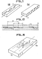
- FIG. 5 represents an embodiment of a slotted guide 11, of the same type as that described in FIG. 3 but having an improvement due to the particular shape of the wave guide which is of the "spine" type - or ridge waveguide in Anglo-Saxon terms. In this figure is shown only one slot.
- such a waveguide is less dispersive than a conventional rectangular guide because it moves the cutoff frequency away from the fundamental mode.
- This has the advantage of a lower frequency sensitivity of the pointing direction of the radiating beam emitted by the guide.
- the slots 12 are not very coupled to the guide because the currents propagating in this type of guide are almost all longitudinal - the transverse currents appearing on the short sides of the guide being very weak -, so that the slots 12 do not not disturb them. Only the recess 13 located in the center of each slot 12 cuts these currents therefore produces the coupling.
- the coupling coefficient of the slots 12 of the guide 11 is evaluated geometrically, therefore is not very sensitive to the operating frequency of the waveguide with radiating slots.
Abstract
Guide d'onde rectangulaire à fentes à rayonnement direct dont chaque fente rayonnante (5) de longueur L voisine de λ est placée sur un côté du guide (6) parallèlement aux lignes de courant et possèdant un décrochement (7) en son centre, réalisé perpendiculairement aux lignes de courant.Rectangular waveguide with direct radiation slits, each radiating slit (5) of length L close to λ is placed on one side of the guide (6) parallel to the current lines and having a recess (7) in its center, produced perpendicular to the current lines.
Description
La présente invention concerne un guide d'onde rectangulaire à fentes à rayonnement direct et à large bande de fréquence.The present invention relates to a rectangular waveguide with direct radiation slots and a wide frequency band.
Dans le domaine des antennes Radar, il en existe une sorte particulièrement simple et compacte qui est le guide à fentes rayonnantes excitées en ondes progressives, dont nous allons rappeler le fonctionnement dans ce qui suit.In the field of Radar antennas, there is a particularly simple and compact kind of it which is the guide with radiating slits excited in traveling waves, the operation of which we will recall in the following.
Tout d'abord, une fente rayonne de la puissance lorsqu'elle coupe des lignes de courant. En effet, pouvant être assimilée à une impédance Z mise en série sur les lignes de courant, il apparait une différence de potentiel entre les parois de la fente, donc un rayonnement vers l'extérieur.First, a slit radiates power when it cuts current lines. Indeed, being able to be assimilated to an impedance Z placed in series on the current lines, there appears a potential difference between the walls of the slot, therefore radiation towards the outside.
D'autre part, selon le principe de Babinet, on déduit que le champ rayonné par une fente est de même nature que celui rayonné par un dipôle de même largeur, leurs polarisations respectives étant perpendiculaires.On the other hand, according to the Babinet principle, it is deduced that the field radiated by a slit is of the same nature as that radiated by a dipole of the same width, their respective polarizations being perpendicular.
Par ailleurs, la puissance rayonnée par la fente étant proportionnelle au carré du courant qui la traverse, on peut alors régler le couplage de la fente avec le guide en choisisant sa position et son inclinaison.Furthermore, the power radiated by the slit being proportional to the square of the current flowing through it, one can then adjust the coupling of the slit with the guide by choosing its position and its inclination.
Classiquement, les fentes 1 peuvent être disposées, comme le montre la figure la, longitudinalement sur le grand côté 2 du guide 3, de façon plus ou moins excentrée, ou bien disposées transversalement sur le petit côté 4 du guide, de manière plus ou moins inclinées, comme le montre la figure lb. Bien qu'offrant l'avantage de rayonner la presque totalité de la puissance sous guide, ces fentes présentent l'inconvénient de posséder des conductances variant rapidement en fonction de la fréquence, entraînant par conséquent une variation du couplage des fentes avec le guide et une instabilité de la loi d'illumination qui gouverne le diagramme rayonné et particulièrement les lobes latéraux.Conventionally, the slots 1 can be arranged, as shown in FIG. 1a, longitudinally on the long side 2 of the
Une solution complexe a été apportée à ce problème en excitant chaque fente rayonnante du guide par l'intermédiaire d'un coupleur directif plongeant dans le guide, mais la réalisation en est complexe.A complex solution has been provided to this problem by exciting each radiating slit of the guide by means of a directional coupler immersed in the guide, but the realization is complex.
Le but de la présente invention est de réaliser un guide d'onde rectangulaire à fentes à rayonnement direct présentant de plus l'avantage de fonctionner sur une large bande de fréquences.The object of the present invention is to produce a rectangular waveguide with direct radiation slits which also has the advantage of operating over a wide frequency band.
Le guide d'onde rectangulaire à fentes à rayonnement direct selon l'invention, est tel que chacune de ces fentes rayonnantes, de longueur L voisine de la longueur d'onde (X) de fonctionnement du guide, est placée sur un côté du guide parallèlement aux lignes de courant parcourant ce côté et possède un décrochement pratiqué dans sa partie centrale perpendiculairement aux lignes de courant.The rectangular waveguide with direct radiation slots according to the invention is such that each of these radiating slots, of length L close to the operating wavelength (X) of the guide, is placed on one side of the guide parallel to the current lines running along this side and has a recess made in its central part perpendicular to the current lines.
Selon une autre caractéristique de l'invention, les fentes sont pratiquées sur un grand ou un petit côté du guide d'onde.According to another characteristic of the invention, the slots are formed on a large or a small side of the waveguide.
D'autres caractéristiques et avantages de l'invention apparaîtront dans la description qui suit, illustrée par les figures 2 à 5 suivantes qui, outre la figure 1 concernant l'art antérieur, représentent des exemples de réalisation d'un guide d'onde à fentes rayonnantes selon l'invention.Other characteristics and advantages of the invention will appear in the description which follows, illustrated by the following Figures 2 to 5 which, in addition to Figure 1 relating to the prior art, represent examples of embodiment of a waveguide to radiating slots according to the invention.
Comme cela a été dit plus haut à propos d'un guide à fentes de l'art antérieur ces fentes présentent l'inconvénient d'avoir une conductance variant rapidement en fonction de la fréquence donc empêchent le fonctionnement du guide dans une large bande de fréquences. C'est pourquoi une antenne rayonnante réalisée à partir de nouveaux éléments rayonnants, notamment des fentes selon l'invention, doit être telle que chaque élément doit avoir une admittance de rayonnement, et en particulier une conductance qui est en la partie active, stable en fonction de la fréquence. Il faut de plus que l'élément d'excitation de chaque fente soit adapté à l'admittance de cette dernière et que l'organe de couplage de cet élément du guide évite, autant que possible, toute désadaptation supplémentaire autre que celle nécessairement due au rayonnement lui-même de la fente.As was said above with regard to a slotted guide of the prior art, these slits have the disadvantage of having a conductance which varies rapidly as a function of frequency, therefore preventing the guide from operating in a wide frequency band. . This is why a radiating antenna produced from new radiating elements, in particular slots according to the invention, must be such that each element must have a radiation admittance, and in particular a conductance which is in the active part, stable in frequency function. It is also necessary that the excitation element of each slot is adapted to the admittance of the latter and that the coupling member of this element of the guide avoids, as far as possible, any additional mismatch other than that necessarily due to the radiation itself from the slit.
Les trois conditions sont satisfaites dans le guide d'onde rectangulaire à fentes rayonnantes et à large bande selon l'invention, représenté en vue de dessus par la figure 2.The three conditions are satisfied in the rectangular waveguide with radiating slits and with wide band according to the invention, represented in top view by FIG. 2.
Chaque fente 5 du guide 6 est une fente onde-entière, relativement large - au besoin élargie en double losange - et possède un décrochement 7 dans sa partie centrale, décrochement réalisé perpendiculairement à l'axe longitudinal Δ de la fente. Il est connu qu'un dipôle onde entière, excité en son centre -surtout si ses brins sont relativement larges - a une impédance d'entrée élevée et plus stable en fréquence qu'un dipôle demi-onde. Aussi, selon le principe de Babinet mentionné auparavant on peut dire qu'une fente onde-entière excitée en son centre a une admittance pourvue des mêmes propriétés, soit une basse impédance d'entrée, stable en fréquence. La fente peut avoir une longueur L légèrement inférieure à la longueur d'onde de fonctionnement (0,7 à 0,9 λ) si la fente est élargie, par exemple en double losange car la seconde résonance est alors obtenue pour une longueur légèrement inférieure à λ. Ce phénomène sera encore amélioré, si la fente est couverte ou remplie par un matériau diélectrique pour des raisons de protection ou d'étanchéité.La distance d séparant le centre de deux fentes 5 successives est voisine de la longueur d'onde X de fonctionnement du guide.Each slot 5 of the
Deux cas particuliers de réalisation sont envisagés et représentés sur les figues 3 et 4. Sur la figure 3 où n'est représentée qu'une seule fente, sur un grand côté 9 d'un guide d'onde 110 sont réalisées les fentes 8 élargies en double losange et disposées longitudinalement c'est à dire selon l'axe longitudinal Δ1 du grand côté 9. Etant donnée leur position, les fentes sont parallèles aux lignes de courant, sauf au niveau de leur décrochement 10 qui les coupe. Chaque fente n'est pas excitée sur toute sa longueur L mais uniquement en son centre qui est le point où précisément son impédance de rayonnement est stable en fréquence. La dimension 1 du décrochement 10, qui est perpendiculaire à l'axe longitudinal Δ1 du grand côté du guide, détermine le coefficient de couplage de la fente. Ainsi, le décrochement 10 placé au centre de la fente sert d'élément d'excitation de la fente et d'organe de couplage au guide d'alimentation.Two particular cases of embodiment are envisaged and shown in FIGS. 3 and 4. In FIG. 3 where only one slot is shown, on a long side 9 of a
Le second cas particulier de réalisation représente sur la figure 4, concerne un guide d'onde 15 dont les fentes 16 sont placées sur un petit côté 17 de ce guide, transversalement c'est-à-dire perpendiculairement à l'axe longitudinal Δ2 du guide 15. Les fentes 16 sont réalisées parallèles aux lignes de courant se propageant sur ce petit côté 17 du guide, avec un décrochement 18 situé dans leur partie centrale, ce décrochement coupant alors les lignes de courant, comme cela a été expliqué auparavant. Pour éviter un trop grand coefficient de couplage dû au fait que les fentes 16 sont disposées parallèlement les unes aux autres, on place une fente classique 19 entre chaque fente 16, parallèlement à celles-ci et non excitée puisque ne coupant pas elles-mêmes les lignes de courant, jouant ainsi le rôle de réflecteur.The second particular embodiment shown in FIG. 4 relates to a
La distance d'entre deux fentes 16 excitées est voisine de la longueur d'onde 1 et le décrochement 18 de toutes ces fentes 16 est dans le même sens afin d'éviter un rayonnement en polarisation croisée à phases alternées pouvant altérer la qualité du rayonnement du guide à fentes.The distance between two
Un tel guide d'ondes à fentes, qui par ailleurs présente une assez. grande directivité, permet le rayonnement direct d'une onde polarisée horizontalement, en évitant d'utiliser un polariseur pour transformer une onde polarisée verticalement. Pour cela, on peut réaliser un guide d'onde, comme celui décrit sur la figure 4, dont la section droite est presque carrée, de côté légèrement inférieur à la longueur d'onde de fonctionnement, et polarisé verticalement.Such a slotted waveguide, which moreover has a fairly. high directivity, allows direct radiation of a horizontally polarized wave, avoiding the use of a polarizer to transform a vertically polarized wave. For this, a waveguide, such as that described in FIG. 4, can be produced, the cross section of which is almost square, with a side slightly less than the operating wavelength, and vertically polarized.
La figure 5 représente un mode de réalisation d'un guide à fente 11, du même type que celui décrit sur la figure 3 mais présentant une amélioration due à la forme particulière du guide d'ondes qui est du type "à échine" - ou ridge waveguide en vocable anglo-saxon-. Sur cette figure n'est représentée qu'une seule fente.FIG. 5 represents an embodiment of a slotted guide 11, of the same type as that described in FIG. 3 but having an improvement due to the particular shape of the wave guide which is of the "spine" type - or ridge waveguide in Anglo-Saxon terms. In this figure is shown only one slot.
En effet, de par sa constitution propre, un tel guide d'onde est moins dispersif qu'un guide rectangulaire classique car il éloigne la fréquence de coupure du mode fondamental. Cela présente l'avantage d'une moindre sensibilité en fréquence de la direction de pointage du faisceau rayonnant émis par le guide.Indeed, by its very constitution, such a waveguide is less dispersive than a conventional rectangular guide because it moves the cutoff frequency away from the fundamental mode. This has the advantage of a lower frequency sensitivity of the pointing direction of the radiating beam emitted by the guide.
D'autre part, les fentes 12 sont peu couplées au guide car les courants se propageant dans ce type de guide sont presque tous longitudinaux - les courants transversaux apparaissant sur les petits côtés du guide étant très faibles -, de sorte que les fentes 12 ne les perturbent pas. Seul le décrochement 13 situé au centre de chaque fente 12 coupe ces courants donc produit le couplage.On the other hand, the
De plus, on peut démontrer que le coefficient de couplage des fentes 12 du guide 11 s'évalue géométriquement, donc est peu sensible à la fréquence de fonctionnement du guide d'onde à fentes rayonnantes. La formule suivante :
On a ainsi décrit un guide d'onde rectangulaire à fentes à rayonnement direct présentant l'avantage de fonctionner sur une large bande de fréquences.We have thus described a rectangular waveguide with direct radiation slots having the advantage of operating over a wide frequency band.
Claims (7)
Applications Claiming Priority (2)
| Application Number | Priority Date | Filing Date | Title |
|---|---|---|---|
| FR8117236A FR2513022A1 (en) | 1981-09-11 | 1981-09-11 | WAVEGUIDE WITH RADIANT SLOTS AND BROADBAND FREQUENCY |
| FR8117236 | 1981-09-11 |
Publications (1)
| Publication Number | Publication Date |
|---|---|
| EP0074311A1 true EP0074311A1 (en) | 1983-03-16 |
Family
ID=9262077
Family Applications (1)
| Application Number | Title | Priority Date | Filing Date |
|---|---|---|---|
| EP82401593A Withdrawn EP0074311A1 (en) | 1981-09-11 | 1982-08-27 | Broadband rectangular slotted wave guide |
Country Status (4)
| Country | Link |
|---|---|
| US (1) | US4513291A (en) |
| EP (1) | EP0074311A1 (en) |
| CA (1) | CA1206605A (en) |
| FR (1) | FR2513022A1 (en) |
Cited By (1)
| Publication number | Priority date | Publication date | Assignee | Title |
|---|---|---|---|---|
| CN107076844A (en) * | 2014-08-14 | 2017-08-18 | 谷歌公司 | 90 degree of many sectors of modularization plane visual field Radar Antenna Structure |
Families Citing this family (17)
| Publication number | Priority date | Publication date | Assignee | Title |
|---|---|---|---|---|
| JPS6013481A (en) * | 1983-07-04 | 1985-01-23 | Canon Inc | Vibration wave motor |
| US4581614A (en) * | 1983-07-18 | 1986-04-08 | General Electric Company | Integrated modular phased array antenna |
| GB2183371B (en) * | 1985-10-09 | 1989-09-27 | Canon Kk | Vibration wave motor and drive circuit therefor |
| US5159253A (en) * | 1987-02-24 | 1992-10-27 | Canon Kabushiki Kaisha | Control device for a vibration wave motor |
| USH1421H (en) * | 1990-09-28 | 1995-03-07 | United States Of America | VHF satellite based radar antenna array |
| IL107582A (en) * | 1993-11-12 | 1998-02-08 | Ramot Ramatsity Authority For | Slotted waveguide array antennas |
| FR2812457B1 (en) | 2000-07-28 | 2004-05-28 | Thomson Csf | ACTIVE BI-POLARIZATION MICROWAVE REFLECTOR, ESPECIALLY FOR AN ELECTRONICALLY BALANCED ANTENNA |
| DE10202824A1 (en) * | 2002-01-24 | 2003-07-31 | Marconi Comm Gmbh | Waveguide coupling device |
| US7121735B2 (en) * | 2002-07-08 | 2006-10-17 | Japan Science And Technology Agency | Optical fiber connector, method for manufacturing the same, and optical coupling apparatus |
| EP2068400A1 (en) * | 2007-12-03 | 2009-06-10 | Sony Corporation | Slot antenna for mm-wave signals |
| US9711870B2 (en) * | 2014-08-06 | 2017-07-18 | Waymo Llc | Folded radiation slots for short wall waveguide radiation |
| CN207542369U (en) | 2015-11-05 | 2018-06-26 | 日本电产株式会社 | Radar system and wireless communication system |
| WO2017151163A1 (en) * | 2016-03-01 | 2017-09-08 | The Hillshire Brands Company | System and method for producing formed meat patties |
| US10763566B2 (en) * | 2017-07-20 | 2020-09-01 | Apple Inc. | Millimeter wave transmission line structures |
| US11199611B2 (en) * | 2018-02-20 | 2021-12-14 | Magna Electronics Inc. | Vehicle radar system with T-shaped slot antennas |
| US11424548B2 (en) * | 2018-05-01 | 2022-08-23 | Metawave Corporation | Method and apparatus for a meta-structure antenna array |
| JP7298808B2 (en) | 2018-06-14 | 2023-06-27 | ニデックエレシス株式会社 | slot array antenna |
Citations (8)
| Publication number | Priority date | Publication date | Assignee | Title |
|---|---|---|---|---|
| GB592760A (en) * | 1945-02-06 | 1947-09-29 | Standard Telephones Cables Ltd | Improvements in dipole antenna systems |
| DE917319C (en) * | 1952-06-12 | 1954-08-30 | Siemens Ag | Broadband antenna consisting of a chain connection of radiators |
| FR1134384A (en) * | 1955-05-11 | 1957-04-10 | Thomson Houston Comp Francaise | Slot antenna structure |
| US3183511A (en) * | 1963-03-28 | 1965-05-11 | Hughes Aircraft Co | Broadband waveguide slot radiator with mutually coupled slots of different perimeters and orientation |
| US3189908A (en) * | 1962-01-22 | 1965-06-15 | Joseph H Provencher | Ridged waveguide slot antenna |
| FR2077327A1 (en) * | 1970-01-26 | 1971-10-22 | Sumitomo Electric Industries | |
| FR2189890A1 (en) * | 1972-06-21 | 1974-01-25 | Licentia Gmbh | |
| US3936836A (en) * | 1974-07-25 | 1976-02-03 | Westinghouse Electric Corporation | Z slot antenna |
Family Cites Families (2)
| Publication number | Priority date | Publication date | Assignee | Title |
|---|---|---|---|---|
| GB1145273A (en) * | 1966-03-31 | 1969-03-12 | Marconi Co Ltd | Improvements in or relating to slotted wave guide aerials |
| US3696433A (en) * | 1970-07-17 | 1972-10-03 | Teledyne Ryan Aeronautical Co | Resonant slot antenna structure |
-
1981
- 1981-09-11 FR FR8117236A patent/FR2513022A1/en active Granted
-
1982
- 1982-08-27 EP EP82401593A patent/EP0074311A1/en not_active Withdrawn
- 1982-08-27 US US06/412,210 patent/US4513291A/en not_active Expired - Fee Related
- 1982-09-09 CA CA000411102A patent/CA1206605A/en not_active Expired
Patent Citations (8)
| Publication number | Priority date | Publication date | Assignee | Title |
|---|---|---|---|---|
| GB592760A (en) * | 1945-02-06 | 1947-09-29 | Standard Telephones Cables Ltd | Improvements in dipole antenna systems |
| DE917319C (en) * | 1952-06-12 | 1954-08-30 | Siemens Ag | Broadband antenna consisting of a chain connection of radiators |
| FR1134384A (en) * | 1955-05-11 | 1957-04-10 | Thomson Houston Comp Francaise | Slot antenna structure |
| US3189908A (en) * | 1962-01-22 | 1965-06-15 | Joseph H Provencher | Ridged waveguide slot antenna |
| US3183511A (en) * | 1963-03-28 | 1965-05-11 | Hughes Aircraft Co | Broadband waveguide slot radiator with mutually coupled slots of different perimeters and orientation |
| FR2077327A1 (en) * | 1970-01-26 | 1971-10-22 | Sumitomo Electric Industries | |
| FR2189890A1 (en) * | 1972-06-21 | 1974-01-25 | Licentia Gmbh | |
| US3936836A (en) * | 1974-07-25 | 1976-02-03 | Westinghouse Electric Corporation | Z slot antenna |
Non-Patent Citations (1)
| Title |
|---|
| ELECTRONICS AND COMMUNICATIONS IN JAPAN, vol. 51-B, no. 10, Octobre 1968, pages 61-68, Scripta Pub., Washington (USA); * |
Cited By (1)
| Publication number | Priority date | Publication date | Assignee | Title |
|---|---|---|---|---|
| CN107076844A (en) * | 2014-08-14 | 2017-08-18 | 谷歌公司 | 90 degree of many sectors of modularization plane visual field Radar Antenna Structure |
Also Published As
| Publication number | Publication date |
|---|---|
| US4513291A (en) | 1985-04-23 |
| FR2513022B1 (en) | 1985-03-08 |
| FR2513022A1 (en) | 1983-03-18 |
| CA1206605A (en) | 1986-06-24 |
Similar Documents
| Publication | Publication Date | Title |
|---|---|---|
| EP0074311A1 (en) | Broadband rectangular slotted wave guide | |
| CA2024992C (en) | Planar antenna | |
| EP0145597B1 (en) | Plane periodic antenna | |
| EP3547450A1 (en) | Radiating element with circular polarisation implementing a resonance in a fabry-perot cavity | |
| FR2614472A1 (en) | ANTENNA NETWORK WITH HEXAGONAL CORS | |
| FR2778272A1 (en) | RADIOCOMMUNICATION DEVICE AND BIFREQUENCY ANTENNA MADE ACCORDING TO MICRO-TAPE TECHNIQUE | |
| FR2825837A1 (en) | Compact multiband antenna has superimposed slots and patches | |
| FR2623020A1 (en) | DEVICE FOR EXCITATION OF A WAVEGUIDE IN CIRCULAR POLARIZATION BY A FLANE ANTENNA | |
| EP0082751B1 (en) | Microwave radiator and its use in an electronically scanned antenna | |
| CA2869652A1 (en) | Power distributor comprising a "t" coupler in plane e, radiating network and antenna comprising such a radiating network | |
| EP2625741A1 (en) | Large-area broadband surface-wave antenna | |
| FR2704358A1 (en) | Waveguide polarisation duplexer | |
| EP0467818B1 (en) | Transition element between electromagnetic waveguides, especially between a circular waveguide and a coaxial waveguide | |
| EP0117803A1 (en) | Wideband primary microwave horn radiator and antenna using such a primary radiator | |
| EP0439970B1 (en) | Slotted wave guide radiator with non-inclined slots excited by conductive printed patterns | |
| FR2555823A1 (en) | DEVICE FOR EXCITATION OF A NON-EXCENTRED SLOT SIZED ON THE GREAT SIDE OF A WAVEGUIDE AND SLITTED ANTENNA HAVING SUCH A DEVICE | |
| FR2709604A1 (en) | Antenna for portable radio. | |
| EP1432073B1 (en) | Coaxial collinear antenna | |
| EP1949496B1 (en) | Flat antenna system with a direct waveguide access | |
| CA2392696C (en) | Broad-band scissor-type antenna | |
| EP0065467A1 (en) | Circularly polarised microwave antenna | |
| EP0550320B1 (en) | Waveguide with non-inclined slots activated by metallic inserts | |
| EP0073165A1 (en) | Microwave switch | |
| FR2470457A1 (en) | SLOT NETWORK ANTENNA WITH AMPLITUDE DISTRIBUTION IN A SMALL CIRCULAR OPENING | |
| EP2281320B1 (en) | Coupler for a multiband radiofrequency system |
Legal Events
| Date | Code | Title | Description |
|---|---|---|---|
| PUAI | Public reference made under article 153(3) epc to a published international application that has entered the european phase |
Free format text: ORIGINAL CODE: 0009012 |
|
| AK | Designated contracting states |
Designated state(s): DE FR GB IT NL SE |
|
| 17P | Request for examination filed |
Effective date: 19830804 |
|
| STAA | Information on the status of an ep patent application or granted ep patent |
Free format text: STATUS: THE APPLICATION IS DEEMED TO BE WITHDRAWN |
|
| 18D | Application deemed to be withdrawn |
Effective date: 19850430 |
|
| RIN1 | Information on inventor provided before grant (corrected) |
Inventor name: DRABOWITCH, SERGE |