EP0074187B1 - Regelsysteme für Fluide - Google Patents
Regelsysteme für Fluide Download PDFInfo
- Publication number
- EP0074187B1 EP0074187B1 EP82304255A EP82304255A EP0074187B1 EP 0074187 B1 EP0074187 B1 EP 0074187B1 EP 82304255 A EP82304255 A EP 82304255A EP 82304255 A EP82304255 A EP 82304255A EP 0074187 B1 EP0074187 B1 EP 0074187B1
- Authority
- EP
- European Patent Office
- Prior art keywords
- flapper
- nozzle
- rotatable
- coupled
- fluid
- Prior art date
- Legal status (The legal status is an assumption and is not a legal conclusion. Google has not performed a legal analysis and makes no representation as to the accuracy of the status listed.)
- Expired
Links
- 239000012530 fluid Substances 0.000 title claims description 29
- 238000006073 displacement reaction Methods 0.000 claims description 6
- 229910000831 Steel Inorganic materials 0.000 description 2
- 239000010959 steel Substances 0.000 description 2
- 238000004140 cleaning Methods 0.000 description 1
- 238000005339 levitation Methods 0.000 description 1
- 239000007788 liquid Substances 0.000 description 1
- 239000002184 metal Substances 0.000 description 1
- 230000001105 regulatory effect Effects 0.000 description 1
- 230000000717 retained effect Effects 0.000 description 1
Images

Classifications
-
- G—PHYSICS
- G05—CONTROLLING; REGULATING
- G05D—SYSTEMS FOR CONTROLLING OR REGULATING NON-ELECTRIC VARIABLES
- G05D7/00—Control of flow
- G05D7/01—Control of flow without auxiliary power
- G05D7/018—Control of flow without auxiliary power using rotary sensing element
-
- F—MECHANICAL ENGINEERING; LIGHTING; HEATING; WEAPONS; BLASTING
- F15—FLUID-PRESSURE ACTUATORS; HYDRAULICS OR PNEUMATICS IN GENERAL
- F15C—FLUID-CIRCUIT ELEMENTS PREDOMINANTLY USED FOR COMPUTING OR CONTROL PURPOSES
- F15C3/00—Circuit elements having moving parts
- F15C3/10—Circuit elements having moving parts using nozzles or jet pipes
-
- G—PHYSICS
- G05—CONTROLLING; REGULATING
- G05D—SYSTEMS FOR CONTROLLING OR REGULATING NON-ELECTRIC VARIABLES
- G05D7/00—Control of flow
- G05D7/06—Control of flow characterised by the use of electric means
- G05D7/0617—Control of flow characterised by the use of electric means specially adapted for fluid materials
- G05D7/0629—Control of flow characterised by the use of electric means specially adapted for fluid materials characterised by the type of regulator means
- G05D7/0635—Control of flow characterised by the use of electric means specially adapted for fluid materials characterised by the type of regulator means by action on throttling means
-
- Y—GENERAL TAGGING OF NEW TECHNOLOGICAL DEVELOPMENTS; GENERAL TAGGING OF CROSS-SECTIONAL TECHNOLOGIES SPANNING OVER SEVERAL SECTIONS OF THE IPC; TECHNICAL SUBJECTS COVERED BY FORMER USPC CROSS-REFERENCE ART COLLECTIONS [XRACs] AND DIGESTS
- Y10—TECHNICAL SUBJECTS COVERED BY FORMER USPC
- Y10T—TECHNICAL SUBJECTS COVERED BY FORMER US CLASSIFICATION
- Y10T137/00—Fluid handling
- Y10T137/0971—Speed responsive valve control
- Y10T137/108—Centrifugal mass type [exclusive of liquid]
- Y10T137/1135—Rotating valve and rotating governor
-
- Y—GENERAL TAGGING OF NEW TECHNOLOGICAL DEVELOPMENTS; GENERAL TAGGING OF CROSS-SECTIONAL TECHNOLOGIES SPANNING OVER SEVERAL SECTIONS OF THE IPC; TECHNICAL SUBJECTS COVERED BY FORMER USPC CROSS-REFERENCE ART COLLECTIONS [XRACs] AND DIGESTS
- Y10—TECHNICAL SUBJECTS COVERED BY FORMER USPC
- Y10T—TECHNICAL SUBJECTS COVERED BY FORMER US CLASSIFICATION
- Y10T137/00—Fluid handling
- Y10T137/2278—Pressure modulating relays or followers
- Y10T137/2322—Jet control type
Definitions
- the present invention relates to fluid control systems and more specifically to such systems employing nozzle flapper valves.
- Nozzle flapper valves are well known in the art and are often used as pilot valves in industrial control instruments.
- the conventional electrohydraulic nozzle flapper actuator system includes a nozzle coupled to a pressurised fluid supply and a flapper. As fluid is discharged from the nozzle, it displaces the flapper and the distance between the flapper and the nozzle is proportional to the force exerted by the fluid.
- An electric torque motor is commonly used to ajust the distance between the flapper and the nozzle by moving the flapper, thereby adjusting the pressure of the fluid.
- a fluid control system comprises a nozzle coupled to a supply of pressurised fluid, rotatable flapper means responsive to fluid flow from the nozzle so as, in use, to rotate as a result of that fluid flow, means for displacing the rotatable flapper means as a function of its angular velocity along its axis of rotation, and braking means for placing an adjustable load on the rotatable flapper means.
- the apparatus of the present invention provides a flapper nozzle actuator system which replaces the flapper and torque motor of a conventional flapper nozzle actuator system with a rotatable turbine-like flapper and braking means.
- a generally conventional nozzle coupled to a pressurised fluid supply discharges the fluid against the blades of the turboflapper causing it to rotate and to provide a self-cleaning action.
- the turboflapper is preferably coupled by a shaft and a thrust bearing to the braking means comprised of a d.c. generator and a variably adjusted load.
- the axial thrust bearing displaces the turboflapper along its axis of rotation as a function of its angular velocity which can be regulated by the braking means.
- the displacement of the turboflapper along its axis of rotation is proportioned to the pressure exerted by the fluid.
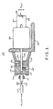
- FIG. 1 a side view partly in cross section illustrates the fluid control system 10 of the present invention.
- the system 10 includes a generally conventional nozzle 11 which is coupled to a supply (not shown) of pressurised fluid, either liquid or gas, by a conduit 12 and a valve or restriction 13.
- the fluid flow discharged through the nozzle 11 impinges against a rotatable turbine-like or turboflapper 15 which is illustrated in greater detail in Figures 2, 3 and 4.
- FIGS 2, 3 and 4 illustrates front, cross-sectional side, and rear views, respectively, of the turboflapper 15.
- the turboflapper 15 is machined from a cylindrical piece of metal and includes a plurality of blades 16 which are responsive to pressurised fluid issuing from the nozzle 11.
- the blades 16 may be in the form of either spirally arranged fins or grooves.
- the turboflapper 15 further includes a threaded hole 17 which receives a set screw 18 to secure a shaft 20 to the turboflapper 15.
- the rear surface of the turboflapper 15 includes a plurality of radial slots 21 milled therein.
- a steel ball bearing 22 is disposed in each of the radial slots 21.
- a backplate 23 having generally curved or concave surfaces 24 is disposed behind the flapper 15.to form a thrust bearing in combination with the steel. ball bearings 22 and the radial slots 21.
- the backplate 23 is fixed to a support 25 and includes an aperture through which extends the shaft 20.
- the shaft 20 extends from a d.c. generator 26 which is also fixed to the support 25. There is a small amount of axial play of the order of 0.04 inches (1 mm.) in the shaft 20 of the d.c. generator 26. Electrical leads 27 of the generator 26 are coupled to a variable resistor 28.
- fluid is admitted to the nozzle 11 from the pressurised supply (not shown) via the conduit 12 and the valve or restriction 13.
- the fluid is discharged from the nozzle 11 and impinges against the turboflapper 15 which is free to rotate.
- the axially flowing fluid is deflected radially by the blades 16 of the turboflapper 15 and exerts a torque on the latter resulting in an angular velocity.
- this arrangement is similar to a radially outward flow hydraulic turbine.
- the torque exerted on the turboflapper 15 causes the shaft 20 of the d.c. generator 26 to rotate at a certain angular velocity.
- the braking system which is comprised of the d.c. generator 26 and the variable resistor 28 is dissipative in nature and can regulate the angular velocity of the turboflapper 15 by adjusting the resistive load provided by the variable resistor 28.
- a friction brake or an eddy current brake could be used to regulate the angular velocity of the turboflapper 15, by creating a load torque on the shaft 20. It should be noted, however, that a particular advantage associated with the preferred embodiment having the d.c. generator 26 is that the device can generate its own electrical power which may be utilised for control purposes.
- the thrust bearing lifts the turboflapper 15 off the curved backplate 23 in response to the axial force of the fluid.
- the axial flow of fluid causes the turboflapper 15 to rotate and the ball bearings 22 to ride up the curved surfaces 24 of the backplate 23 whilst being retained in the slots 21.
- the ball bearings 22 will move radially outwardly, of the backplate 23, thus providing an axial displacement for the turboflapper 15. It should be noted that axial displacement of the turboflapper 15 could be limited by the amount of axial play in the shaft 20 of the generator 26.
- the amount of lift or axial displacement varies only as a function of the angular velocity of the turboflapper 15, thus also making the nozzle outlet area and nozzle flow rate a function of angular velocity.
- the axial displacement of the turboflapper may be provided by a hydrodynamically lubricated axial thrust bearing, a governor or Watts regulator type bearing, or an eddy current induced levitation system.
Landscapes
- Engineering & Computer Science (AREA)
- Physics & Mathematics (AREA)
- General Engineering & Computer Science (AREA)
- General Physics & Mathematics (AREA)
- Automation & Control Theory (AREA)
- Theoretical Computer Science (AREA)
- Fluid Mechanics (AREA)
- Mechanical Engineering (AREA)
- Control Of Turbines (AREA)
- Servomotors (AREA)
- Supply Devices, Intensifiers, Converters, And Telemotors (AREA)
Claims (5)
Applications Claiming Priority (2)
| Application Number | Priority Date | Filing Date | Title |
|---|---|---|---|
| US06/297,532 US4425509A (en) | 1981-08-31 | 1981-08-31 | Turboflapper nozzle systems |
| US297532 | 1981-08-31 |
Publications (2)
| Publication Number | Publication Date |
|---|---|
| EP0074187A1 EP0074187A1 (de) | 1983-03-16 |
| EP0074187B1 true EP0074187B1 (de) | 1986-02-12 |
Family
ID=23146710
Family Applications (1)
| Application Number | Title | Priority Date | Filing Date |
|---|---|---|---|
| EP82304255A Expired EP0074187B1 (de) | 1981-08-31 | 1982-08-11 | Regelsysteme für Fluide |
Country Status (7)
| Country | Link |
|---|---|
| US (1) | US4425509A (de) |
| EP (1) | EP0074187B1 (de) |
| JP (1) | JPS5846203A (de) |
| AU (1) | AU549407B2 (de) |
| CA (1) | CA1178538A (de) |
| DE (1) | DE3269066D1 (de) |
| IN (1) | IN158522B (de) |
Families Citing this family (3)
| Publication number | Priority date | Publication date | Assignee | Title |
|---|---|---|---|---|
| US4511806A (en) * | 1984-05-22 | 1985-04-16 | Air Ltd. | Pressure drop power generation |
| US20090071734A1 (en) * | 2007-05-01 | 2009-03-19 | Hurkett Earl R | Method and Apparatus for Generating Electrical Power with Compressed Air and Vehicle Incorporating the Same |
| WO2012014324A1 (ja) | 2010-07-30 | 2012-02-02 | 三菱電機株式会社 | 電気車の推進制御装置、および鉄道車両システム |
Family Cites Families (5)
| Publication number | Priority date | Publication date | Assignee | Title |
|---|---|---|---|---|
| FR633236A (fr) * | 1927-04-23 | 1928-01-25 | Turbine | |
| BE500182A (de) * | 1950-01-25 | |||
| FR1162555A (fr) * | 1955-10-12 | 1958-09-15 | Physique Appliquee Lab De | Perfectionnement aux dispositifs pour bobiner les fils, en particulier les fils électriques |
| US3275037A (en) * | 1964-01-10 | 1966-09-27 | Union Oil Co | Fluid flow control device |
| US3426594A (en) * | 1967-04-14 | 1969-02-11 | Foxboro Co | Flyball integrator cutoff |
-
1981
- 1981-08-31 US US06/297,532 patent/US4425509A/en not_active Expired - Fee Related
-
1982
- 1982-08-11 JP JP57139660A patent/JPS5846203A/ja active Pending
- 1982-08-11 EP EP82304255A patent/EP0074187B1/de not_active Expired
- 1982-08-11 DE DE8282304255T patent/DE3269066D1/de not_active Expired
- 1982-08-11 CA CA000409249A patent/CA1178538A/en not_active Expired
- 1982-08-13 IN IN617/DEL/82A patent/IN158522B/en unknown
- 1982-08-16 AU AU87189/82A patent/AU549407B2/en not_active Ceased
Also Published As
| Publication number | Publication date |
|---|---|
| CA1178538A (en) | 1984-11-27 |
| AU549407B2 (en) | 1986-01-23 |
| US4425509A (en) | 1984-01-10 |
| JPS5846203A (ja) | 1983-03-17 |
| DE3269066D1 (en) | 1986-03-27 |
| AU8718982A (en) | 1983-03-10 |
| IN158522B (de) | 1986-12-06 |
| EP0074187A1 (de) | 1983-03-16 |
Similar Documents
| Publication | Publication Date | Title |
|---|---|---|
| US5127792A (en) | Centrifugal pump having magnet bearing | |
| US5186608A (en) | Hydraulic low pitch switch for propeller pitch change system | |
| AU2008332770B2 (en) | Low power electric operated thermostatic mixing valve | |
| US3563618A (en) | Gas- or liguid-lubricated hydrostatic double-action thrust | |
| JPH056017B2 (de) | ||
| US5739607A (en) | Hybrid spindle bearing | |
| EP0074187B1 (de) | Regelsysteme für Fluide | |
| JPS6295613A (ja) | 流体制御弁 | |
| GB2260821A (en) | LVDT for propeller pitch change system | |
| JPS6038295A (ja) | 可変ピツチプロペラ用ピツチ制御装置 | |
| SE500920C2 (sv) | Anordning för ett axiallager i en borrmaskin | |
| US3776279A (en) | System for changing fluid movement into electrical energy | |
| US4229139A (en) | Water powered high speed motor | |
| CA2668482C (en) | Arrangement for sealing between two parts of a hydraulic turbomachine moveable relative to one another | |
| EP0867628A2 (de) | Lageranordnung für eine drehbare Welle | |
| US3443593A (en) | Hydrodynamically balanced rotary valve | |
| US5261784A (en) | Variable pressure pitot pump | |
| US4177673A (en) | Anemometer | |
| US4273390A (en) | Bearing system with thrust compensation means | |
| US3774882A (en) | Process flow meter | |
| JPH04214975A (ja) | 容積形ポンプ用調整装置 | |
| US7238000B2 (en) | Pneumatic high speed motor with pressure activated speed governor | |
| SE512644C2 (sv) | Värmealstrare till motorfordon | |
| JPS6141925Y2 (de) | ||
| CA2075604A1 (en) | Counterthrust seal for a rotary fluid machine |
Legal Events
| Date | Code | Title | Description |
|---|---|---|---|
| PUAI | Public reference made under article 153(3) epc to a published international application that has entered the european phase |
Free format text: ORIGINAL CODE: 0009012 |
|
| AK | Designated contracting states |
Designated state(s): DE FR GB IT SE |
|
| 17P | Request for examination filed |
Effective date: 19830606 |
|
| GRAA | (expected) grant |
Free format text: ORIGINAL CODE: 0009210 |
|
| AK | Designated contracting states |
Designated state(s): DE FR GB IT SE |
|
| REF | Corresponds to: |
Ref document number: 3269066 Country of ref document: DE Date of ref document: 19860327 |
|
| ET | Fr: translation filed | ||
| ITF | It: translation for a ep patent filed | ||
| RAP2 | Party data changed (patent owner data changed or rights of a patent transferred) |
Owner name: VICKERS, INCORPORATED |
|
| PLBE | No opposition filed within time limit |
Free format text: ORIGINAL CODE: 0009261 |
|
| STAA | Information on the status of an ep patent application or granted ep patent |
Free format text: STATUS: NO OPPOSITION FILED WITHIN TIME LIMIT |
|
| 26N | No opposition filed | ||
| REG | Reference to a national code |
Ref country code: FR Ref legal event code: TP |
|
| ITTA | It: last paid annual fee | ||
| PGFP | Annual fee paid to national office [announced via postgrant information from national office to epo] |
Ref country code: DE Payment date: 19930713 Year of fee payment: 12 |
|
| PGFP | Annual fee paid to national office [announced via postgrant information from national office to epo] |
Ref country code: FR Payment date: 19930715 Year of fee payment: 12 |
|
| PGFP | Annual fee paid to national office [announced via postgrant information from national office to epo] |
Ref country code: SE Payment date: 19930719 Year of fee payment: 12 |
|
| PGFP | Annual fee paid to national office [announced via postgrant information from national office to epo] |
Ref country code: GB Payment date: 19930729 Year of fee payment: 12 |
|
| PG25 | Lapsed in a contracting state [announced via postgrant information from national office to epo] |
Ref country code: GB Effective date: 19940811 |
|
| PG25 | Lapsed in a contracting state [announced via postgrant information from national office to epo] |
Ref country code: SE Effective date: 19940812 |
|
| EAL | Se: european patent in force in sweden |
Ref document number: 82304255.1 |
|
| GBPC | Gb: european patent ceased through non-payment of renewal fee |
Effective date: 19940811 |
|
| PG25 | Lapsed in a contracting state [announced via postgrant information from national office to epo] |
Ref country code: FR Effective date: 19950428 |
|
| PG25 | Lapsed in a contracting state [announced via postgrant information from national office to epo] |
Ref country code: DE Effective date: 19950503 |
|
| EUG | Se: european patent has lapsed |
Ref document number: 82304255.1 |
|
| REG | Reference to a national code |
Ref country code: FR Ref legal event code: ST |