EP0073159B1 - Bouchon d'étanchéité, notamment pour réservoirs de carburant - Google Patents
Bouchon d'étanchéité, notamment pour réservoirs de carburant Download PDFInfo
- Publication number
- EP0073159B1 EP0073159B1 EP82401279A EP82401279A EP0073159B1 EP 0073159 B1 EP0073159 B1 EP 0073159B1 EP 82401279 A EP82401279 A EP 82401279A EP 82401279 A EP82401279 A EP 82401279A EP 0073159 B1 EP0073159 B1 EP 0073159B1
- Authority
- EP
- European Patent Office
- Prior art keywords
- cap
- sealing member
- spring
- sealing
- ring
- Prior art date
- Legal status (The legal status is an assumption and is not a legal conclusion. Google has not performed a legal analysis and makes no representation as to the accuracy of the status listed.)
- Expired
Links
- 239000002828 fuel tank Substances 0.000 title claims description 4
- 238000007789 sealing Methods 0.000 claims description 14
- 229920003052 natural elastomer Polymers 0.000 claims description 2
- 229920001194 natural rubber Polymers 0.000 claims description 2
- 229920003051 synthetic elastomer Polymers 0.000 claims description 2
- 239000005061 synthetic rubber Substances 0.000 claims description 2
- 210000005069 ears Anatomy 0.000 description 5
- 229920001971 elastomer Polymers 0.000 description 2
- 239000000945 filler Substances 0.000 description 2
- 239000000446 fuel Substances 0.000 description 2
- 239000005060 rubber Substances 0.000 description 2
- 241001314298 Verbascum sinuatum Species 0.000 description 1
- 238000009434 installation Methods 0.000 description 1
- 238000012423 maintenance Methods 0.000 description 1
- 238000004519 manufacturing process Methods 0.000 description 1
- 238000007747 plating Methods 0.000 description 1
- 229920002994 synthetic fiber Polymers 0.000 description 1
- 238000002604 ultrasonography Methods 0.000 description 1
- 238000003466 welding Methods 0.000 description 1
Images
Classifications
-
- B—PERFORMING OPERATIONS; TRANSPORTING
- B60—VEHICLES IN GENERAL
- B60K—ARRANGEMENT OR MOUNTING OF PROPULSION UNITS OR OF TRANSMISSIONS IN VEHICLES; ARRANGEMENT OR MOUNTING OF PLURAL DIVERSE PRIME-MOVERS IN VEHICLES; AUXILIARY DRIVES FOR VEHICLES; INSTRUMENTATION OR DASHBOARDS FOR VEHICLES; ARRANGEMENTS IN CONNECTION WITH COOLING, AIR INTAKE, GAS EXHAUST OR FUEL SUPPLY OF PROPULSION UNITS IN VEHICLES
- B60K15/00—Arrangement in connection with fuel supply of combustion engines or other fuel consuming energy converters, e.g. fuel cells; Mounting or construction of fuel tanks
- B60K15/03—Fuel tanks
- B60K15/04—Tank inlets
- B60K15/0406—Filler caps for fuel tanks
-
- Y—GENERAL TAGGING OF NEW TECHNOLOGICAL DEVELOPMENTS; GENERAL TAGGING OF CROSS-SECTIONAL TECHNOLOGIES SPANNING OVER SEVERAL SECTIONS OF THE IPC; TECHNICAL SUBJECTS COVERED BY FORMER USPC CROSS-REFERENCE ART COLLECTIONS [XRACs] AND DIGESTS
- Y10—TECHNICAL SUBJECTS COVERED BY FORMER USPC
- Y10S—TECHNICAL SUBJECTS COVERED BY FORMER USPC CROSS-REFERENCE ART COLLECTIONS [XRACs] AND DIGESTS
- Y10S220/00—Receptacles
- Y10S220/32—Radiator cap
-
- Y—GENERAL TAGGING OF NEW TECHNOLOGICAL DEVELOPMENTS; GENERAL TAGGING OF CROSS-SECTIONAL TECHNOLOGIES SPANNING OVER SEVERAL SECTIONS OF THE IPC; TECHNICAL SUBJECTS COVERED BY FORMER USPC CROSS-REFERENCE ART COLLECTIONS [XRACs] AND DIGESTS
- Y10—TECHNICAL SUBJECTS COVERED BY FORMER USPC
- Y10S—TECHNICAL SUBJECTS COVERED BY FORMER USPC CROSS-REFERENCE ART COLLECTIONS [XRACs] AND DIGESTS
- Y10S220/00—Receptacles
- Y10S220/33—Gasoline tank cap
Definitions
- the present invention relates to the production of sealing plugs, with constant torque and flat seal, intended in particular for fuel tanks for motor vehicles, or for oil sumps.
- a type of plug is already known as described in French patent No 2274850 (WASO), which consists of a body comprising a cylindrical extension directed towards the chute and an element subject to said cylindrical extension, this element supporting ears which run through a helical ramp located inside the chute, a seal and at least one spring bearing on the internal face of the cap body and acting on the aforementioned flat seal. Note, however, that the seal is not securely held at its internal periphery and that only the pressure of the spring ensures its plating on the chute, no device being provided to ensure a rigid wedging, in abutment, between the seal and the lower part of the cap.
- the subject of the present invention is a sealing plug in accordance with the preamble of claim 1 (of the type stated in document FR.A No 2274850) making it possible to overcome the above difficulties and to maintain a constant force of crushing of the joint. of the cap on the fuel filler neck, this ensuring an excellent seal, without modifying the torque to be exerted on the cap during its tightening.
- This problem is solved by the features set out in the characterizing part of claim 1.
- the body of the cap preferably made of synthetic material, the filler neck of the fuel tank on which it is applied and the helical ramp 3 of the neck 2, traversed by the upper part of the two ears 4 of the plug.
- the body of the plug 1 has an internal cylindrical extension 5 and directed towards the chute, in which an element 6 supporting ears 4 fits, this is provided with a shoulder 7 facing the lower edge 8 of the cylindrical extension 5 , a flat seal 9 of natural or synthetic rubber being wedged in a leaktight manner between these two clamping means.
- the leak-tightness of the chute 2 is ensured by the seal 9, the internal rim of which is crushed between the shoulder 7 of the element 6 and the rim 8 of the extension 5. These two parts are secured in a suitable position everywhere adequate means that clipping, welding, ultrasound, etc.
- the outer edge of the seal 9 is pressed against the chute 2 under the action of the springs 11-12. This is done according to a constant effort, via the ring 10.
- the latter movable along the axis of the plug against the springs 11-12, compensates for the depression of the plug, when the ears 4 describe the helical ramp 3 located inside the chute 2. This arrangement therefore makes it possible to exert a practically constant torque on the stopper throughout the operation for closing the chute.
- the device according to the invention allows a tight closure while requiring only a limited and constant tightening torque, requiring no particular effort to be made to bring the plug into closure.
Landscapes
- Engineering & Computer Science (AREA)
- Life Sciences & Earth Sciences (AREA)
- Sustainable Development (AREA)
- Sustainable Energy (AREA)
- Chemical & Material Sciences (AREA)
- Combustion & Propulsion (AREA)
- Transportation (AREA)
- Mechanical Engineering (AREA)
- Closures For Containers (AREA)
- Cooling, Air Intake And Gas Exhaust, And Fuel Tank Arrangements In Propulsion Units (AREA)
Description
- La présente invention se rapporte à la réalisation de bouchons d'étanchéité, à couple constant et à joint plat, destinés en particulier à des réservoirs de carburant pour véhicules automobiles, ou à des carters d'huile.
- Les fonctions d'étanchéité et de facilité de mise en place de tels bouchons ne sont actuellement pas assurées de manière satisfaisante à l'aide de joints plats en caoutchouc.
- En effet, on se heurte à des impératifs contraires pour lesquels les compromis auxquels on fait appel ne sont pas très heureux.
- L'étanchéité parfaite implique un couple de serrage élevé pour le vissage du bouchon. Dans le cas contraire, un montage facile se traduit par des fuites de carburant dans certaines situations.
- On connaît déjà un type de bouchon tel que décrit dans le brevet français No 2274850 (WASO), qui est constitué d'un corps comportant un prolongement cylindrique dirigé vers la goulotte et un élément assujetti audit prolongement cylindrique, cet élément supportant des oreilles qui parcourent une rampe hélicoïdale située à l'intérieur de la goulotte, un joint d'étanchéité et au moins un ressort prenant appui sur la face interne du corps du bouchon et agissant sur le joint d'étanchéité plat précité. On remarquera toutefois que le joint n'est pas solidement maintenu à sa périphérie interne et que seule la pression du ressort assure son plaquage sur la goulotte, aucun dispositif n'étant prévu pour assurer un calage rigide, en butée, entre le joint et la partie inférieure du bouchon.
- De cela résulte une incertitude quant au maintien de l'étanchéité du réservoir dans toutes les situations, même les plus critiques.
- La présente invention a pour objet un bouchon d'étanchéité conforme au préambule de la revendication 1 (du type énoncé dans le document FR.A No 2274850) permettant de pallier les difficultés ci-dessus et de maintenir un effort constant d'écrasement du joint du bouchon sur la goulotte de remplissage de carburant, cela assurant une excellente étanchéité, sans pour autant modifier le couple à exercer sur le bouchon au cours de son serrage. Ce problème est résolu par les caractéristiques énoncées dans la partie caractérisante de la revendication 1.
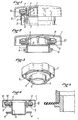
- L'invention sera décrite au regard des fig. 1 à 5 ci-jointes, données à titre d'exemple non limitatif, et qui décrivent respectivement:
- - lafig. 1, une coupe du bouchon de l'invention selon un plan passant par son axe longitudinal, montrant sa structure en position de montage sur la goulotte;
- - la fig. 2 est une vue analogue du bouchon démonté;
- - la fig. 3 est une perspective vue de dessous du bouchon;
- - la fig. 4 est une coupe analogue à celle des fig. 1 et 2 d'une variante du bouchon;
- - la fig. 5 est un détail grossi de la fig. 4, montrant la fixation du joint.
- Sur la fig. 1, on voit le corps du bouchon 1, de préférence réalisé en matière synthétique, la goulotte de remplissage du réservoir de carburant sur laquelle il s'applique et la rampe 3 hélicoïdale de la goulotte 2, parcourue par la partie supérieure des deux oreilles 4 du bouchon.
- Le corps du bouchon 1 comporte un prolongement cylindrique 5 interne et dirigé vers la goulotte, dans lequel s'adapte un élément 6 supportant des oreilles 4, celui-ci est pourvu d'un épaulement 7 faisant face au rebord inférieur 8 du prolongement cylindrique 5, un joint plat 9 en caoutchouc naturel ou synthétique étant coincé de façon étanche entre ces deux moyens de serrage.
- Supportée par le joint 9 et concentrique au prolongement 5 est disposée une bague 10 profilée en U, à l'intérieur de laquelle se trouve un ressort 11 à lame ondulée ou bien, selon la variante de la fig. 4, plusieurs ressorts 12 hélicoïdaux.
- L'étanchéité de la goulotte 2 est assurée par le joint 9, dont le rebord interne est écrasé entre l'épaulement 7 de l'élément 6 et le rebord 8 du prolongement 5. Ces deux pièces sont solidarisées en position convenable partout moyen adéquattel que clipsage, par soudure, au moyen d'ultrasons, etc. Le rebord externe du joint 9 est plaqué sur la goulotte 2 sous l'action des ressorts 11-12. Cela est effectué selon un effort constant, via la bague 10. Cette dernière, mobile selon l'axe du bouchon à l'encontre des ressorts 11-12, compense l'enfoncement du bouchon, lorsque les oreilles 4 décrivent la rampe 3 hélicoïdale située à l'intérieur de la goulotte 2. Cette disposition permet donc d'exercer un couple de rotation pratiquement constant sur le bouchon tout au long de l'opération d'obturation de la goulotte.
- Lorsque les oreilles 4 de l'élément 6 du bouchon arrivent en butée de fin de course de la rampe 3, la hauteur de la bague 10 et les caractéristiques de la rampe 3 ayant été dimensionnées en conséquence, la bague 10 entre alors en contact avec la face inférieure du bouchon 1, s'opposant ainsi à toute progression complémentaire et donc au franchissement de ladite butée.
- On voit bien, de ce qui précède, que le dispositif selon l'invention autorise une fermeture étanche tout en ne nécessitant qu'un couple de serrage limité et constant, ne demandant aucun effort particulier à fournir pour amener le bouchon en butée de fermeture.
- De plus, cela est obtenu à l'aide d'un simple joint plat en caoutchouc, pouvant être fabriqué par découpe, et donc relativement bon marché, par rapport aux moyens antérieurs assurant la même fonction.
Claims (5)
Applications Claiming Priority (2)
| Application Number | Priority Date | Filing Date | Title |
|---|---|---|---|
| FR8115667A FR2511345A1 (fr) | 1981-08-13 | 1981-08-13 | Bouchon d'etancheite, notamment pour reservoirs de carburant |
| FR8115667 | 1981-08-13 |
Publications (2)
| Publication Number | Publication Date |
|---|---|
| EP0073159A1 EP0073159A1 (fr) | 1983-03-02 |
| EP0073159B1 true EP0073159B1 (fr) | 1985-03-20 |
Family
ID=9261445
Family Applications (1)
| Application Number | Title | Priority Date | Filing Date |
|---|---|---|---|
| EP82401279A Expired EP0073159B1 (fr) | 1981-08-13 | 1982-07-07 | Bouchon d'étanchéité, notamment pour réservoirs de carburant |
Country Status (5)
| Country | Link |
|---|---|
| US (1) | US4416391A (fr) |
| EP (1) | EP0073159B1 (fr) |
| DE (1) | DE3262653D1 (fr) |
| ES (1) | ES273693Y (fr) |
| FR (1) | FR2511345A1 (fr) |
Families Citing this family (14)
| Publication number | Priority date | Publication date | Assignee | Title |
|---|---|---|---|---|
| US4515245A (en) * | 1983-08-15 | 1985-05-07 | Rockford Enterprises, Inc. | Oil filler extension |
| FR2627748B1 (fr) * | 1988-02-29 | 1990-12-07 | Journee Paul Sa | Dispositif de fermeture etanche d'un reservoir |
| DE9106814U1 (de) * | 1991-06-04 | 1991-07-25 | Fa. Andreas Stihl, 7050 Waiblingen | Schraubverschluß für einen Flüssigkeitsbehälter |
| GB9207683D0 (en) * | 1992-04-08 | 1992-05-27 | Britax Wingard Ltd | Tank closure |
| US5167340A (en) * | 1992-04-13 | 1992-12-01 | Shaw Aero Devices, Inc. | Fuel cap with a molded seal |
| US5732841A (en) * | 1996-03-19 | 1998-03-31 | Tesma International Inc. | Fuel cap |
| US5601205A (en) * | 1996-04-01 | 1997-02-11 | Ford Motor Company | Fuel tank assembly |
| US6213331B1 (en) * | 1998-02-09 | 2001-04-10 | Shaw Aero Development, Inc. | Fuel cap having biased seal |
| DE20317572U1 (de) * | 2003-11-12 | 2004-03-18 | Gerdes Gmbh | Tankdeckel mit Leckstromsicherung |
| USD568450S1 (en) * | 2005-08-23 | 2008-05-06 | King Jr Lloyd Herbert | Combo drain |
| US8801315B2 (en) | 2009-10-14 | 2014-08-12 | Cosmopak Usa, Llc | Airless cosmetics applicator with airtight sealing dual cap |
| USD721423S1 (en) * | 2013-04-08 | 2015-01-20 | Adam Donald Jacques | Lockable cap |
| USD748227S1 (en) * | 2014-02-24 | 2016-01-26 | W. L. Gore & Associates Gmbh | Vent cap |
| USD749197S1 (en) * | 2014-02-24 | 2016-02-09 | W. L. Gore & Associates Gmbh | Vent cap |
Family Cites Families (6)
| Publication number | Priority date | Publication date | Assignee | Title |
|---|---|---|---|---|
| US3703245A (en) * | 1971-08-19 | 1972-11-21 | Gen Motors Corp | Filler cap |
| GB1395586A (en) * | 1972-05-18 | 1975-05-29 | Avm Corp | Fluid valves |
| GB1481473A (en) * | 1974-06-12 | 1977-07-27 | Waso Ltd | Vent valve |
| US4049152A (en) * | 1976-01-09 | 1977-09-20 | Makap Limited | Closure caps for vessels |
| JPS5937476Y2 (ja) * | 1976-03-25 | 1984-10-17 | 日本ラヂエーター株式会社 | 燃料タンクの蓋 |
| DE2852454A1 (de) * | 1978-12-04 | 1980-06-19 | Blau Kg Kraftfahrzeugtech | Verschlussdeckel mit in der aussenkappe drehfest eingelagertem innendeckelteil, sowie gegenseitig wirkender absprengung der aussenkappe bei unvorhersehbar angreifenden extremkraeften |
-
1981
- 1981-08-13 FR FR8115667A patent/FR2511345A1/fr active Granted
-
1982
- 1982-07-07 DE DE8282401279T patent/DE3262653D1/de not_active Expired
- 1982-07-07 EP EP82401279A patent/EP0073159B1/fr not_active Expired
- 1982-08-05 ES ES1982273693U patent/ES273693Y/es not_active Expired
- 1982-08-13 US US06/408,046 patent/US4416391A/en not_active Expired - Fee Related
Also Published As
| Publication number | Publication date |
|---|---|
| ES273693U (es) | 1983-12-01 |
| ES273693Y (es) | 1984-07-16 |
| US4416391A (en) | 1983-11-22 |
| DE3262653D1 (en) | 1985-04-25 |
| FR2511345B1 (fr) | 1985-02-22 |
| FR2511345A1 (fr) | 1983-02-18 |
| EP0073159A1 (fr) | 1983-03-02 |
Similar Documents
| Publication | Publication Date | Title |
|---|---|---|
| EP0073159A1 (fr) | Bouchon d'étanchéité, notamment pour réservoirs de carburant | |
| FR2733467A1 (fr) | Ensemble a clapet pour reservoir de carburant | |
| EP0547942B1 (fr) | Dispositif de raccord rapide pour la liaison étanche entre eux de deux tubes ou tuyaux rigides ou semi-rigides | |
| FR2587433A1 (fr) | Double joint metallique pour une vanne de securite de puits d'exploitation de petrole et/ou de gaz | |
| EP0781692A1 (fr) | Mécanisme d'essuie-glace comportant des moyens perfectionnés de guidage et d'étanchéité pour la traversée d'une tÔle par un arbre d'entraînement | |
| FR2488661A1 (fr) | Dispositif accumulateur de pression | |
| EP0292346B1 (fr) | Garniture de étanchéité à anneau de réaction incorporé, notamment pour obturateur | |
| FR2472516A1 (fr) | Bouchon d'une seule piece en matiere plastique | |
| FR2629553A1 (fr) | Soupape de mise a l'atmosphere d'un reservoir de carburant | |
| FR2696996A1 (fr) | Dispositif de bouchage temporaire pour bouteille. | |
| EP0518717B1 (fr) | Bouchon de radiateur pour véhicules à moteur | |
| FR2568560A1 (fr) | Tete de bouchage pour machine a capsuler des bouteilles | |
| FR2686065A1 (fr) | Dispositif d'obturation de flacon avec joint d'etancheite. | |
| FR2762807A1 (fr) | Embout de fermeture pour tubulure de remplissage d'un reservoir de carburant d'un vehicule automobile | |
| FR2759035A1 (fr) | Dispositif de remplissage d'un reservoir de carburant de vehicule automobile comportant un contact souple de mise a la masse | |
| WO2008062144A2 (fr) | Dispositif d'assemblage pour un actionneur electromagnetique d'un injecteur pour moteur a combustion interne | |
| EP0085010B1 (fr) | Coupleur auto-obturateur, notamment pour fluide ou réfrigérant | |
| FR2642497A1 (fr) | Joint annulaire d'etancheite assurant la jonction etanche d'un element tubulaire et d'une paroi traversee par cet element | |
| EP0546911B1 (fr) | Joint annulaire d'étanchéité et réservoir de carburant | |
| FR2743506A1 (fr) | Filtre pour liquide | |
| EP4249787B1 (fr) | Dispositif d'amortissement de pression pour un circuit de fluide | |
| EP0676583B1 (fr) | Boítier de projecteur automobile à capot d'accès | |
| EP0213013B1 (fr) | Bouchon d'étanchéité, notamment pour couvre-culasse de véhicule automobile | |
| FR2725490A3 (fr) | Clapet etanche et bouchon pressostatique comportant au moins un tel clapet | |
| FR2509789A1 (fr) | Bouchon pour un circuit de fluide, tel qu'un circuit de refroidissement de moteur a combustion interne |
Legal Events
| Date | Code | Title | Description |
|---|---|---|---|
| PUAI | Public reference made under article 153(3) epc to a published international application that has entered the european phase |
Free format text: ORIGINAL CODE: 0009012 |
|
| 17P | Request for examination filed |
Effective date: 19820710 |
|
| AK | Designated contracting states |
Designated state(s): BE CH DE GB IT LI NL SE |
|
| ITF | It: translation for a ep patent filed | ||
| GRAA | (expected) grant |
Free format text: ORIGINAL CODE: 0009210 |
|
| AK | Designated contracting states |
Designated state(s): BE CH DE GB IT LI NL SE |
|
| REF | Corresponds to: |
Ref document number: 3262653 Country of ref document: DE Date of ref document: 19850425 |
|
| PLBE | No opposition filed within time limit |
Free format text: ORIGINAL CODE: 0009261 |
|
| STAA | Information on the status of an ep patent application or granted ep patent |
Free format text: STATUS: NO OPPOSITION FILED WITHIN TIME LIMIT |
|
| 26N | No opposition filed | ||
| PGFP | Annual fee paid to national office [announced via postgrant information from national office to epo] |
Ref country code: NL Payment date: 19870731 Year of fee payment: 6 |
|
| PGFP | Annual fee paid to national office [announced via postgrant information from national office to epo] |
Ref country code: DE Payment date: 19890530 Year of fee payment: 8 |
|
| PGFP | Annual fee paid to national office [announced via postgrant information from national office to epo] |
Ref country code: BE Payment date: 19890619 Year of fee payment: 8 |
|
| PG25 | Lapsed in a contracting state [announced via postgrant information from national office to epo] |
Ref country code: GB Effective date: 19890707 |
|
| PG25 | Lapsed in a contracting state [announced via postgrant information from national office to epo] |
Ref country code: SE Effective date: 19890708 |
|
| PG25 | Lapsed in a contracting state [announced via postgrant information from national office to epo] |
Ref country code: LI Effective date: 19890731 Ref country code: CH Effective date: 19890731 |
|
| PG25 | Lapsed in a contracting state [announced via postgrant information from national office to epo] |
Ref country code: NL Effective date: 19900201 |
|
| GBPC | Gb: european patent ceased through non-payment of renewal fee | ||
| NLV4 | Nl: lapsed or anulled due to non-payment of the annual fee | ||
| REG | Reference to a national code |
Ref country code: CH Ref legal event code: PL |
|
| PG25 | Lapsed in a contracting state [announced via postgrant information from national office to epo] |
Ref country code: BE Effective date: 19900731 |
|
| BERE | Be: lapsed |
Owner name: CIE DES PRODUITS INDUSTRIELS DE L'OUEST CPIO Effective date: 19900731 |
|
| PG25 | Lapsed in a contracting state [announced via postgrant information from national office to epo] |
Ref country code: DE Effective date: 19910403 |
|
| EUG | Se: european patent has lapsed |
Ref document number: 82401279.3 Effective date: 19900418 |