EP0073005B1 - Farb-Kathodenstrahlröhren-Anordnung - Google Patents
Farb-Kathodenstrahlröhren-Anordnung Download PDFInfo
- Publication number
- EP0073005B1 EP0073005B1 EP82107485A EP82107485A EP0073005B1 EP 0073005 B1 EP0073005 B1 EP 0073005B1 EP 82107485 A EP82107485 A EP 82107485A EP 82107485 A EP82107485 A EP 82107485A EP 0073005 B1 EP0073005 B1 EP 0073005B1
- Authority
- EP
- European Patent Office
- Prior art keywords
- component
- cathode ray
- ray tube
- tube device
- color cathode
- Prior art date
- Legal status (The legal status is an assumption and is not a legal conclusion. Google has not performed a legal analysis and makes no representation as to the accuracy of the status listed.)
- Expired
Links
Images

Classifications
-
- H—ELECTRICITY
- H04—ELECTRIC COMMUNICATION TECHNIQUE
- H04N—PICTORIAL COMMUNICATION, e.g. TELEVISION
- H04N9/00—Details of colour television systems
- H04N9/12—Picture reproducers
- H04N9/16—Picture reproducers using cathode ray tubes
- H04N9/28—Arrangements for convergence or focusing
-
- H—ELECTRICITY
- H01—ELECTRIC ELEMENTS
- H01J—ELECTRIC DISCHARGE TUBES OR DISCHARGE LAMPS
- H01J29/00—Details of cathode-ray tubes or of electron-beam tubes of the types covered by group H01J31/00
- H01J29/46—Arrangements of electrodes and associated parts for generating or controlling the ray or beam, e.g. electron-optical arrangement
- H01J29/70—Arrangements for deflecting ray or beam
- H01J29/701—Systems for correcting deviation or convergence of a plurality of beams by means of magnetic fields at least
- H01J29/702—Convergence correction arrangements therefor
- H01J29/705—Dynamic convergence systems
-
- H—ELECTRICITY
- H01—ELECTRIC ELEMENTS
- H01J—ELECTRIC DISCHARGE TUBES OR DISCHARGE LAMPS
- H01J2229/00—Details of cathode ray tubes or electron beam tubes
- H01J2229/56—Correction of beam optics
- H01J2229/563—Aberrations by type
- H01J2229/5637—Colour purity
Definitions
- the present invention relates to a color cathode ray tube (CRT) device of the in-line type.
- CRT color cathode ray tube
- the distribution of the magnetic field generated by a deflection yoke is made suitably non-uniform, and a magnetic field control element incorporated in an end portion of the electron gun together with the suitable non-uniform magnetic field distribution converge three in-line electron beams onto an image surface of the tube.
- possible variations of the magnetic field generated by the deflection yoke, the magnetic field distribution of the in-line arrangement of the three electron beams emitted from the electron gun, of the electron beam and the deflection yoke in combination as well as possible assembly errors in mass-production have caused precise convergence of the three electron beams throughout the surface of the image plane to be difficult.
- the amount of convergence error to be further corrected in a mass-produced color CRT device of this type is about 0.5-1.0 mm.
- An object of the present invention is to provide a color cathode ray tube device of the in-line type in which the arrangement of the dynamic convergence component with respect to the electron gun is optimized to improve the correction sensitivity of the-component to thereby minimize the electric power required to realize the correction.
- a color cathode ray tube device of the in-line type comprising: an electron gun with a main electron lens gap; a deflection yoke; a static convergence component and a dynamic convergence component; characterised in that said dynamic convergence component is disposed with its center plane orthogonal to the axis of the cathode ray tube and within a range of distance 3d along said axis on either side of the center plane of the main electron lens gap of width d, and located in a region between said deflection yoke and said static convergence component.
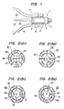
- FIG. 1 is a schematic illustration of the neck portion of a color CRT device 1 of the in-line type, which is constructed according to a typical example of a known proposal.
- a three beam electron gun 3 for producing three in-line electron beams 31, 32 and 33 is incorporated in the neck portion 2.
- Various voltages are applied through a base portion 4 to the electron gun 3 to cause the latter to emit the beams 31, 32 and 33.
- These electron beams are passed through a deflection yoke 5 which produces a specific non-uniform magnetic field distribution and are deflected horizontally and vertically towards given points on the image surface.
- a static convergence correction magnetic field generating component 6 (referred to as a static convergence component hereinafter) composed of two, four and six pole magnets is provided around the outer periphery of the electron gun 3, in which the three electron beams 31, 32 and 33 are corrected in convergence error around a central portion of the image plane and converged to a point in the central area by regulating the magnetic field strengths of two four-pole magnets and two six-pole magnets. Color purity correction at the image plane is also performed by regulating the magnetic field strength of the two-pole magnet.
- the three beams 31, 32 and 33 to be converged to a point in the central area of the image plane pass through the magnetic field produced by the deflection yoke 5 and are deflected horizontally and vertically, It is required that the three beams be convergeable at any point whether at peripheral or central areas of the image plane.
- the magnetic field produced by the deflection yoke 5 should be distributed non-uniformly in a specific horizontal and vertical pattern and a coma correction should be provided.
- the coma correction is performed by a coma correcting magnetic field control component (referred to as coma control component hereinafter) 7 provided at an end of the electron gun 3 so that a deflection sensitivity correction of the center beam 32 and the side beams 31 and 33 may be performed.
- coma control component referred to as coma control component hereinafter
- the side beams 31 and 33 are corrected by dynamic convergence component 8 provided between the deflection yoke 5 and the static convergence component 6 so that these beams 31 and 33 are overlapped on the central beam 32. Therefore, the amount of convergence to be corrected can be reduced to an amount smaller than 0.5 mm.
- the dynamic convergence component 8 is composed of two four-pole magnetic field generating elements 81 and two six-pole magnetic field generating elements 32 as shown in Figures 2A and 2B, respectively.
- the elements 81 are composed of a ferrite core ring 83 and two sets of four coils 85 would at equi-distance positions on the ring 83, the sets of coils 85 being offset in phase by 45° from each other as shown in Figure 2A, and the elements 42 are composed of a similar ferrite core ring 84 and two sets of six coils 86 wound equi-angularly on the ring 84, the sets of the coils 86 being off-set in phase by 30° from each other.
- the core ring 84 may be eliminated and instead, the core ring 83 may be used concurrently.
- the convergence correction is performed by varying the magnetic field strengths produced thereby by regulating the currents flowing through the coils 85 and coils 86, respectively.
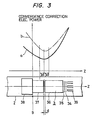
- the electron gun 3 which is of the general bipotential type, is composed of three in-line cathodes 39, a first grid 34, a second grid 35, a third grid electrode 36, a fourth grid electrode 37 and a shield cup electrode 38. It should be noted that the so-called multi-stage convergence type electron gun which has been widely used recently is basically similar to the gun shown in Figure 3.
- the only difference between the guns is that a single prefocussing lens is provided in front of a main electric lens located between the third and fourth electrodes 36 and 37 in the bipotential type gun, while a plurality of various prefocussing lenes are arranged in the multi-stage type gun.
- the character Z in Figure 3 depicts the axis of the tube.
- the coma control component 7 ( Figure 1) is provided in a border portion 9 between the fourth electrode 37 and the shield cup electrode 38.
- a curve a shows the variation of the electric power required for convergence correction when no coma control component 7 is provided.
- the electric power required for the dynamic convergence component 8 becomes a minimum around the main lens of the gun 3, located between electrodes 37 and 37, regardless of the presence of the coma control component 7.
- the minimum value is increased. The minimum value of the power for correction depends upon the size of the component 7 as well as the relative distance from the component 8 to the component 7.
- Figure 4 shows the vertical component distribution of the deflection field in which curve a shows the field distribution when there is no dynamic convergence component 8 within the deflection field and curve b shows that when the dynamic convergence component 8 is provided within the deflection field.
- curve a shows the field distribution when there is no dynamic convergence component 8 within the deflection field
- curve b shows that when the dynamic convergence component 8 is provided within the deflection field.
- the vertical field strength on the gun side is remarkably reduced.
- the variation in the horizontal field distribution is slightly affected by the presence of the component8. The reason for this is that a ferrite core ring is used as the dynamic convergence component 8 on which the coils are wound to produce the four-pole magnetic fields and six-pole magnetic fields, and the gun side component of the vertical magnetic field is shunted by the ring core.
- the size and configuration of the component 7 should be increased for magnetic field control as compared with the case when the component 8 is not used. Consequently, the electric power required by the dynamic convergence component 8 is undesirably increased. In order to resolve this problem, it is necessary to separate the coma control component 7 from the dynamic convergence component 8. That is, as shown in Figure 4, the component 7 should be arranged outside the dynamic convergence component 8.
- FIG 5 shows an example of the arrangement of the dynamic convergence component 8, according to the present invention. That is, the dynamic convergence component 8 producing the four- and six-pole magnetic fields is disposed on the outer periphery of the neck portion 2 and between the deflection yoke 5 and the static convergence component 6.
- the dynamic convergence component 8 is disposed in the main lens portion exhibiting the minimum power for correction, as shown in Figure 3, i.e., in the electron lens portion composed of the third and fourth electrodes 36 and 37.
- the coma control component 7 is disposed in a plane orthogonal to the axis Z and is positioned in the side of the yoke 5 outside of a region 10 ( Figure 4) defined by the dynamic convergence component 8. Therefore, it is possible to improve the correction sensitivity of the dynamic convergence component 8 and reduce the power for correction without undesirably increasing the size of the coma control component 7.
- the dynamic convergence component 8 is set exactly at the point where the power for correction becomes a minimum.
- the center plane 87 of the dynamic convergence element 8 may be set within a range of 3d about a reference plane containing the center of the gap 11, where d is the width of the gap 11 between the electrodes 36 and 37, which may be, for example, 1 mm.
- an electron gun 3 of the bipotential type is described, the invention is likewise applicable with other multi-stage converging type guns. That is, in a multi-stage converging gun, the electron beams emitted by the cathode 39 are converged by successive electric lenses, and therefore, the last electric lens may be considered as the "main" electric lens referred to above.
- the arrangement of the dynamic convergence component with respect to the electron gun is optimized so that the correction sensitivity of the dynamic convergence component is improved and the electric power for convergence correction is reduced.
Landscapes
- Engineering & Computer Science (AREA)
- Multimedia (AREA)
- Signal Processing (AREA)
- Video Image Reproduction Devices For Color Tv Systems (AREA)
Claims (5)
Applications Claiming Priority (2)
| Application Number | Priority Date | Filing Date | Title |
|---|---|---|---|
| JP56129707A JPS5830294A (ja) | 1981-08-18 | 1981-08-18 | カラ−陰極線管装置 |
| JP129707/81 | 1981-08-18 |
Publications (3)
| Publication Number | Publication Date |
|---|---|
| EP0073005A2 EP0073005A2 (de) | 1983-03-02 |
| EP0073005A3 EP0073005A3 (en) | 1984-05-30 |
| EP0073005B1 true EP0073005B1 (de) | 1986-07-16 |
Family
ID=15016209
Family Applications (1)
| Application Number | Title | Priority Date | Filing Date |
|---|---|---|---|
| EP82107485A Expired EP0073005B1 (de) | 1981-08-18 | 1982-08-17 | Farb-Kathodenstrahlröhren-Anordnung |
Country Status (5)
| Country | Link |
|---|---|
| US (1) | US4455541A (de) |
| EP (1) | EP0073005B1 (de) |
| JP (1) | JPS5830294A (de) |
| KR (1) | KR870000320B1 (de) |
| DE (1) | DE3272013D1 (de) |
Families Citing this family (8)
| Publication number | Priority date | Publication date | Assignee | Title |
|---|---|---|---|---|
| GB2111744B (en) * | 1981-09-25 | 1985-05-30 | Denki Onkyo Co Ltd | Convergence apparatus for colour cathode-ray tube |
| JPS60100342A (ja) * | 1983-11-04 | 1985-06-04 | Mitsubishi Electric Corp | 陰極線管用偏向装置 |
| NL8601511A (nl) * | 1986-06-11 | 1988-01-04 | Philips Nv | Kathodestraalbuis met magnetische focusseerlens. |
| JPH0736319B2 (ja) * | 1987-05-28 | 1995-04-19 | 株式会社東芝 | カラ−受像管装置 |
| US5828167A (en) * | 1995-07-24 | 1998-10-27 | Hitachi, Ltd. | Color cathode ray tube with a dynamic convergence device and color display system employing same |
| US6376981B1 (en) * | 1997-12-29 | 2002-04-23 | U.S. Philips Corporation | Color display device having quadrupole convergence coils |
| CN1315052A (zh) * | 1999-06-22 | 2001-09-26 | 皇家菲利浦电子有限公司 | 具有四极会聚线圈的彩色显示装置 |
| EP1105911A1 (de) * | 1999-06-22 | 2001-06-13 | Koninklijke Philips Electronics N.V. | Farbanzeigevorrichtung mit quadrupol-konvergenzspulen |
Family Cites Families (7)
| Publication number | Priority date | Publication date | Assignee | Title |
|---|---|---|---|---|
| US3440468A (en) * | 1965-12-02 | 1969-04-22 | Nippon Columbia | Three electron gun color picture tube |
| JPS536489B1 (de) * | 1970-09-09 | 1978-03-08 | ||
| JPS5813577Y2 (ja) * | 1974-06-10 | 1983-03-16 | ソニー株式会社 | カラ−インキヨクセンカン |
| JPS50155926U (de) * | 1974-06-10 | 1975-12-24 | ||
| US3906418A (en) * | 1974-08-14 | 1975-09-16 | Gte Sylvania Inc | Means for effecting dynamic vertical convergence in an in-line plural beam cathode ray tube |
| JPS5324726A (en) * | 1976-08-20 | 1978-03-07 | Hitachi Ltd | Color receiving tube |
| US4138628A (en) * | 1977-07-26 | 1979-02-06 | Rca Corporation | Magnetizing method for use with a cathode ray tube |
-
1981
- 1981-08-18 JP JP56129707A patent/JPS5830294A/ja active Granted
-
1982
- 1982-08-06 KR KR8203534A patent/KR870000320B1/ko not_active Expired
- 1982-08-17 DE DE8282107485T patent/DE3272013D1/de not_active Expired
- 1982-08-17 US US06/408,999 patent/US4455541A/en not_active Expired - Fee Related
- 1982-08-17 EP EP82107485A patent/EP0073005B1/de not_active Expired
Also Published As
| Publication number | Publication date |
|---|---|
| JPS6242430B2 (de) | 1987-09-08 |
| KR870000320B1 (ko) | 1987-02-26 |
| JPS5830294A (ja) | 1983-02-22 |
| US4455541A (en) | 1984-06-19 |
| KR840001383A (ko) | 1984-04-30 |
| DE3272013D1 (en) | 1986-08-21 |
| EP0073005A2 (de) | 1983-03-02 |
| EP0073005A3 (en) | 1984-05-30 |
Similar Documents
| Publication | Publication Date | Title |
|---|---|---|
| EP0424888B1 (de) | Farbbildkathodenstrahlröhre | |
| US4143345A (en) | Deflection yoke with permanent magnet raster correction | |
| US3930185A (en) | Display system with simplified convergence | |
| EP0073005B1 (de) | Farb-Kathodenstrahlröhren-Anordnung | |
| US4857796A (en) | Cathode-ray tube with electrostatic convergence means and magnetic misconvergence correcting mechanism | |
| CA1120095A (en) | Method of correcting deflection defocusing in self-converged color crt display systems | |
| JP3638311B2 (ja) | カラー受像管 | |
| KR930002657B1 (ko) | 음극선관내의 복수의 전자빔을 수속하는 장치 | |
| US4881015A (en) | Color cathode-ray apparatus having an improved deflection unit | |
| Barbin et al. | New color picture tube system for portable TV receivers | |
| US5225736A (en) | Color cathode ray tube apparatus | |
| EP0438584B1 (de) | Anordnung zur korrektur des vertikalen kommafehlers | |
| EP0456224B1 (de) | Farbkathodenstrahlröhrenvorrichtung | |
| EP0310242B1 (de) | Farbanzeigesystem mit selbstkonvergierendem Ablenkjoch mit Rasterverzerrungskorrektur | |
| US4656390A (en) | Color picture tube device | |
| US4305055A (en) | Television display system incorporating a coma corrected deflection yoke | |
| EP0348912B1 (de) | Farbbildröhre | |
| KR0133797Y1 (ko) | 칼라 음극선관의 퓨리티 컨버전스 마그네트 | |
| US6060824A (en) | Color cathode ray tube with specific placement of magnetic plate | |
| US4723094A (en) | Color picture device having magnetic pole pieces | |
| US4117379A (en) | Method of adjusting a magnetic deflection unit of a cathode ray tube, cathode ray tube having a deflection unit or reference points adjusted according to said method, and a deflection unit provided with reference points adjusted according to said method | |
| US6239560B1 (en) | System for correcting electron beam from single cathode in color CRT | |
| USRE31552E (en) | Electron beam and deflection yoke alignment for producing convergence of plural in-line beams | |
| JP3039944B2 (ja) | コンバーゼンス装置 | |
| Barten | The 20AX system and picture tube |
Legal Events
| Date | Code | Title | Description |
|---|---|---|---|
| PUAI | Public reference made under article 153(3) epc to a published international application that has entered the european phase |
Free format text: ORIGINAL CODE: 0009012 |
|
| AK | Designated contracting states |
Designated state(s): DE FR GB |
|
| PUAL | Search report despatched |
Free format text: ORIGINAL CODE: 0009013 |
|
| AK | Designated contracting states |
Designated state(s): DE FR GB |
|
| 17P | Request for examination filed |
Effective date: 19840709 |
|
| GRAA | (expected) grant |
Free format text: ORIGINAL CODE: 0009210 |
|
| AK | Designated contracting states |
Kind code of ref document: B1 Designated state(s): DE FR GB |
|
| REF | Corresponds to: |
Ref document number: 3272013 Country of ref document: DE Date of ref document: 19860821 |
|
| ET | Fr: translation filed | ||
| PLBE | No opposition filed within time limit |
Free format text: ORIGINAL CODE: 0009261 |
|
| STAA | Information on the status of an ep patent application or granted ep patent |
Free format text: STATUS: NO OPPOSITION FILED WITHIN TIME LIMIT |
|
| 26N | No opposition filed | ||
| PGFP | Annual fee paid to national office [announced via postgrant information from national office to epo] |
Ref country code: GB Payment date: 19930730 Year of fee payment: 12 |
|
| PGFP | Annual fee paid to national office [announced via postgrant information from national office to epo] |
Ref country code: FR Payment date: 19930805 Year of fee payment: 12 |
|
| PGFP | Annual fee paid to national office [announced via postgrant information from national office to epo] |
Ref country code: DE Payment date: 19930812 Year of fee payment: 12 |
|
| PG25 | Lapsed in a contracting state [announced via postgrant information from national office to epo] |
Ref country code: GB Effective date: 19940817 |
|
| GBPC | Gb: european patent ceased through non-payment of renewal fee |
Effective date: 19940817 |
|
| PG25 | Lapsed in a contracting state [announced via postgrant information from national office to epo] |
Ref country code: FR Effective date: 19950428 |
|
| PG25 | Lapsed in a contracting state [announced via postgrant information from national office to epo] |
Ref country code: DE Effective date: 19950503 |
|
| REG | Reference to a national code |
Ref country code: FR Ref legal event code: ST |