US3440468A - Three electron gun color picture tube - Google Patents
Three electron gun color picture tube Download PDFInfo
- Publication number
- US3440468A US3440468A US597777A US3440468DA US3440468A US 3440468 A US3440468 A US 3440468A US 597777 A US597777 A US 597777A US 3440468D A US3440468D A US 3440468DA US 3440468 A US3440468 A US 3440468A
- Authority
- US
- United States
- Prior art keywords
- electron
- electron gun
- picture tube
- magnetic
- lateral
- Prior art date
- Legal status (The legal status is an assumption and is not a legal conclusion. Google has not performed a legal analysis and makes no representation as to the accuracy of the status listed.)
- Expired - Lifetime
Links
- 238000010894 electron beam technology Methods 0.000 description 46
- 239000003086 colorant Substances 0.000 description 11
- 230000004907 flux Effects 0.000 description 7
- 238000010276 construction Methods 0.000 description 4
- 230000009467 reduction Effects 0.000 description 4
- OAICVXFJPJFONN-UHFFFAOYSA-N Phosphorus Chemical compound [P] OAICVXFJPJFONN-UHFFFAOYSA-N 0.000 description 3
- 230000009471 action Effects 0.000 description 2
- 230000004075 alteration Effects 0.000 description 2
- 101100434906 Mus musculus Angptl8 gene Proteins 0.000 description 1
- 230000015556 catabolic process Effects 0.000 description 1
- 238000006731 degradation reaction Methods 0.000 description 1
- 230000006866 deterioration Effects 0.000 description 1
- 239000011521 glass Substances 0.000 description 1
- 239000000696 magnetic material Substances 0.000 description 1
- 239000002184 metal Substances 0.000 description 1
- 230000004048 modification Effects 0.000 description 1
- 238000012986 modification Methods 0.000 description 1
- 238000003466 welding Methods 0.000 description 1
Images


Classifications
-
- H—ELECTRICITY
- H01—ELECTRIC ELEMENTS
- H01J—ELECTRIC DISCHARGE TUBES OR DISCHARGE LAMPS
- H01J29/00—Details of cathode-ray tubes or of electron-beam tubes of the types covered by group H01J31/00
- H01J29/46—Arrangements of electrodes and associated parts for generating or controlling the ray or beam, e.g. electron-optical arrangement
- H01J29/70—Arrangements for deflecting ray or beam
- H01J29/701—Systems for correcting deviation or convergence of a plurality of beams by means of magnetic fields at least
- H01J29/702—Convergence correction arrangements therefor
-
- H—ELECTRICITY
- H01—ELECTRIC ELEMENTS
- H01J—ELECTRIC DISCHARGE TUBES OR DISCHARGE LAMPS
- H01J2229/00—Details of cathode ray tubes or electron beam tubes
- H01J2229/56—Correction of beam optics
- H01J2229/568—Correction of beam optics using supplementary correction devices
- H01J2229/5681—Correction of beam optics using supplementary correction devices magnetic
- H01J2229/5684—Magnetic materials, e.g. soft iron
Definitions
- This invention relates to a three electron gun color picture tube, and more particularly to a novel three electron gun color picture tube which is simple in construction and excellent in resolution.
- a conventional type of three electron gun color picture tube such, for example, as a shadow mask type color picture tube employs lateral and radial convergence units and a purifying magnet so as to ensure that the electron beam emitted from each electron gun may impinge upon its corresponding color phosphors on the screen of the picture tube through the shadow mask.
- the purifying magnet is located in the vicinity of the main electron lens system of the electron gun, so that the lens action of the main electron lens system is liable to be subject to the influence of the purifying magnet. It is likely to lead to the reduction of resolution of the picture tube.
- the lateral covergence unit is disposed at the preceding stage of the main electron lens system, more precisely, between the cathode of the electron gun and the main electron lens system thereof. The electron beam is aifected by the action of the lateral convergence unit before entering the main electron lens system, so that the electron beam is liable to deviate from the axis of the lens to cause a deterioration in resolution.
- one object of this invention is to provide a novel three electron gun color picture tube which is excellent in resolution.
- Another object of this invention is to provide a three electron gun color picture tube which is capable of chormaticity control without using a purifying magnet, which is likely to degrade the resolution of the tube, and is capable of the reproduction of accurate colors with high resolution.
- Another object of this invention is to provide a three electron gun color picture tube in which lateral and radial convergence units are located at the stage subsequent to the main electron lens system of the electron gun.
- Another object of this invention is to provide a three electron gun color picture tube of excellent resolution which is provided with only radial and lateral convergence units for controlling the paths of electron beams.
- Still another object of this invention is to provide a three electron gun picture tube which is provided with means by which the electron beam emitted from each electron gun corresponding to one of the three primary colors, i.e., red R, green G and blue B, can be shifted independently of the other electron beams in a lateral direction.
- FIGURE 1 is a side view, partly in cross-section, schematically illustrating a conventional color picture tube employing three bipotential electron guns;
- FIGURE 2A and 2B are views in elevation, and partly in cross-section, schematically illustrating a radial convergence unit and a lateral convergence unit employed in conventional three electron gun color picture tube;
- FIGURE 3 is a side view, partly in cross-section, schematically illustrating one example of a color picture tube of this invention employing three bipotential electron guns;
- FIGURE 4 is a side view, partly in cross-section, diagramatically illustrating another embodiment of the color picture tube of this invention employing three bipotential electron guns;
- FIGURES 5A and 5B are cross-sectional views taken along the line II in FIGURE 3, respectively illustrating embodiments of a lateral convergence unit applicable to the picture tube of this invention
- FIGURE 6 is a perspective view of the principal part of the units shown in FIGURES 5A and 5B;
- FIGURE 7 is a cross-sectional view, similar to FIGURE 5, showing another embodiment of the lateral convergence unit applicable to the picture tube of this invention.
- FIGURE 8 is a perspective view illustrating one element of an internal magnetic pole in the lateral convergence unit depicted in FIGURE 7;
- FIGURE 9 is a perspective view showing entirely an internal magnetic pole of the lateral convergence unit shown in FIGURE 7;
- FIGURE 10 is a perspective view showing another element of the internal magnetic pole of the lateral convergence unit depicted in FIGURE 7;
- FIGURES 11A and 11B are cross-sectional views, similar to FIGURE 5, illustrating other examples of the lateral convergence unit according to this invention.
- FIGURE 12 is a perspective view illustrating the principal part of a picture tube employing the lateral convergence unit depicted in FIGURE 11;
- FIGURE 13 is a perspective view of the principal part of the picture tube shown in FIGURE 4;
- FIGURE 14 is a cross-sectional view taken along the line IIII in FIGURE 4;
- FIGURES 15A, 15B and 15C are cross-sectional views illustrating still other examples of the internal magnetic pole of the lateral convergence unit of this invention.
- FIGURE 16 is a side view, partly in cross-section, illustrating one embodiment of a color picture tube of this invention employing three unipotential-type electron guns.
- FIGURE 1 there is diagrammatically illustrated the principal part of a conventional color picture tube of the type employing three bipotential-type electron guns.
- Reference character T indicates generally an envelope of the picture tube, in the neck portion of which are disposed, for example, three bipotential-type electron guns 1 each corresponding to each of the three primary colors, i.e. red, green and blue, although there are shown only two electron guns in the figure.
- Each of the electron guns 1 comprises first, second, third and fourth grids G G G and G
- an electrostatic focusing lens is formed by the third and fourth grids G and G
- the grid electrodes of each electron gun 1 are mechanically attached by, for example, support pins (not shown) to an insulating supporter 20 made of, for instance, the so-called beading glass or the like disposed between two adjacent electron guns 1. Accordingly, the grid electrodes are maintained at predetermined positions relative to one another.
- Reference numeral 2 identifies a radial convergence unit including a radial convergence magnet 3 and a radial convergence magnetic pole 4.
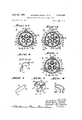
- the radial convergence magnet 3 and the magnetic pole 4 respectively consist of three convergence magnet elements 3R, 3G and 3B and three magnetic pole elements 4R, 4G and 4B each arranged for each electron gun 1 as depicted in FIGURE 2A.
- the magnetic pole elements 4R, 4G and 4B are each separated from the others by shield plates 5 radially extending from, for example, the axis of the envelope.
- Reference numeral 6 designates a lateral convergence unit having a lateral convergence magnet 7, which is diagramatically depicted in FIGURE 2B.
- the lateral convergence unit 6 comprises an external magnet 7 in common to the respective electron guns 1 and internal magnetic poles and 15' attached to the third grid of one of the electron guns 1 corresponding to the blue color, and its magnetic line of force is established as indicated by dotted lines in the figure.
- the lateral convergence unit is designed so that adjustment (of chiefly the external magnet 7) will lead to shifting of the electron beam representative of the blue color in a direction opposite to that of the electron beams of the red and green colors emanating from the other electron guns and crossing the radial direction of the envelope at right angles thereto, namely in a lateral direction such as indicated by the arrow a
- the electron beams representative of the red and green colors are also shifted in the lateral direction, namely in a direction indicated by the arrows a and a in FIGURE 2B.
- Reference numeral 8 indentifies a purifying magnet, by which the electron beams emitted from the electron guns 1 are simultaneously shifted circularly about the axes of the respective electron guns to perform color purity control.
- the lateral convergence unit 6 is located at a position corresponding to the third grid G of each electron gun I or at a position preceding the electrostatic focusing lens formed between the third and fourth grids G and G namely on that side from which the electron beam enters the lens, as shown in the figure.
- the lateral convergence unit 6 disposed at such a location, it is likely that the electron beam entering the electrostatic focusing lens deviates from the axis of the lens system to deteriorate the focusing characteristic of the electron beam to degrade the resolution of a picture displayed on the phosphor screen. The degradation of resolution is more prominent in the unipotential electron gun.
- the unipotential electron gun employs the so-called limiting aperture in the third grid for limiting the diameter of the electron beam path, it is likely that the control of the electron beam by the lateral convergence magnet 7 and the purifying magnet 8 exerts an influence upon the brightness of the picture.
- a lateral convergence unit 16 is positioned rearwardly of the main electron lens of each electron gun and forwardly of the radial convergence unit 2 with respect to the advance direction of the electron beam, as shown in FIGURE 3, and in this case the purifying magnet needed in the prior art may be dispensed with.
- the parts corresponding to those in FIGURES l and 2 are identified at the same numeral references for the sake of brevity. F urther, it is also possible to position the lateral convergence unit 16 at the stage following the radial convergence unit 2 placed next to the main electron lens with respect to the advance direction of the electron beam, as depicted in FIGURE 4.
- the lateral convergence unit 16 is composed of three lateral convergence magnets 17R, 17G and 17B mounted on the outside of the envelope T corresponding to electron guns 1R, 1G and 1B for red, green and blue colors and three internal magnetic poles 15R, 15G and 15B mounted on the electron guns.
- These lateral convergence magnets 17R, 17G and 17B and internal magnetic poles 15R, 15G and 15B are fixedly disposed in opposing relation to the electrodes subsequent to those constituting the main electrostatic lenses of the electron guns.
- the electron guns employed are, for instance, bipotential' ones such as shown in FIGURE 3
- the lateral convergence magnets 17R, 17G and 17B and the internal magnetic poles 15R, 15G and 15B are positioned in Opposing relation to the fourth grids G, of the electron guns 1R, 1G and 1B as illustrated in FIGURE 5A.
- the relative arrangement of the lateral convergence magnets, the internal magnetic poles and the electron guns are such that the electron gun, for example, 1G, is disposed between a pair of the opposing lateral convergence magnet and internal magnetic pole, for instance, 17G and 15G.
- each of the internal magnetic poles 15R, 156 and 15B is an elongated magnetic plate 21 of such a shape as shown in FIGURE 6.
- the magnetic plate 21 has a generally Q-shaped cross-section such that its centrally curved portion 21a wraps an approximately portion of the circumferential surface of the cylindrical metal case forming the fourth grid 6., of each electron gun.
- the elongated magnetic plate 21 is attached to the fourth grid G, of each of the electron guns 1R, 1G and 1B by means of, for example, Welding in such a manner that the curved portion 21a of the magnetic plate 21 wraps a 180 portion of the fourth grid G on the side of the axis of the envelope T, and both ends 21b and 21c of the magnetic plate 21 are embedded in the insulating supporters 20 disposed on either side of each electron gun.
- each magnetic plate 21 supports each fourth grid G on the insulating supporters 20 and at the same time constitutes each of the internal magnetic poles 15R, 15G and 15B of the convergence unit 16.
- the magnet 17 is adapted to be movable about the axis of the envelope T so as to shift the electron beam emanating from the electron gun I in a direction crossing the radial direction of the envelope T, namely in the lateral direction of the envelope T, as indicated by the arrow in FIGURE 5B.
- FIGURE 58 illustrates a modified form of the internal piece 22 is mounted on the circumferential surface of the fourth grid G, of each electron gun in such a manner that the flat portion 22a is opposite ,to the central or curved portion 21a of the magnetic plate 21 across the electron gun.
- the use of such a C-shaped magnetic pole piece 22 provides enhancement of the parallelism and uniformity of the magnetic flux in the center of each electron gun, namely in each electron beam path.
- FIGURE 7 there is illustrated another example of the internal magnetic poles 15R, 15G and 15B, which employs magnetic pole pieces 23 and 24 other than the aforementioned magnetic plate 12, the magnetic pole pieces 23 and 24 being disposed in opposing relation to each other between the magnetic plate 21 and the magnet 17.
- the magnetic pole piece 23 is a flat magnetic plate of such a shape as shown in, for example, FIGURE 8.
- the magnetic pole piece 23 of such a configuration is disposed in the fourth grid G, of each electron gun in such a manner as to cross at right angles the radial direction of the envelope T passing through both the axis OO of the envelope T and the axis of the electron gun 1.
- the magnetic pole piece 23 has pawls 25 at its both ends.
- the other magnetic pole piece 24 is a magnetic plate bent in a substantially O-shaped cross-section as shown in FIGURE but having a fiat end portion such as identified at 24a.
- the magnetic pole piece 24 of such a configuration is assembled with the grid 6., in a manner so that the fiat portion 24a lies in opposing relation to the magnetic pole piece 23 across the grid G within the electron gun, as clearly seen from FIGURE 9.
- FIGURE 11B there is illustrated a little modified form of the magnetic plates 26.
- the magnetic plates ,26 each constituting each internal magnetic pole 15R, 15G or 15B have centrally disposed flat portions 26; respectively, and the magnetic plates 26 are arranged in such a manner that their fiat portions form an equilateral triangle about the axis 0 of the envelope T so as to enhance the uniformity of the magnetic field around each electron beam path. It has been ascertained that the use of such magnetic plates 26 enables reduction of the aberration of the electron lens to the electron beams.
- FIGURE 13 illustrates in perspective one part of still another example of the lateral convergence unit 16, utilizing the shield plates 5 of the radial convergence unit 2 as the internal magnetic poles 15 of the lateral convergence unit 16.
- the shield plates 5 of the radial convergence unit 2 are extended toward the screen along the axis of the envelope T, namely in the advance direction of the electron beam, and the extensions are used as the internal magnetic poles 15 of the lateral convergence unit 16.
- FIGURE 14 shows in cross section such a lateral convergence unit 16, in which three lateral convergence magnets 17R, 17G and 17B, each corresponding to each of the electron beam paths of the red, green and blue colors defined by the extensions 5a of the shield plates 5, are mounted on the outside of the envelope T in opposing relation to the extensions 5a.
- FIGURE 15B illustrates another example of the internal magnetic poles 15R, 15G and 15B, each of which has a flat portion 15a at its center.
- the magnetic field around each electron beam path can be made more uniform by the employment of such internal magnetic poles, which are disposed in a manner so that their flat portions 15a form an equilateral triangle about the axis 0 of the envelope T. It has been ascertained that such a construction of the internal magnetic poles provides a reduction of aberration of the electron lens to the electron beam. Further, if substantially U-shaped magnetic pole pieces 15' are each provided in opposing relation to the flat portion 15a of each magnetic pole 15 as shown in FIGURE 15C, the magnetic field established therebetween can be made more uniform and the magnetic flux produced by each magnet 17 can be caught more easily.
- reference numeral 19 identitfies a cylindrical support of a non-magnetic material for supporting the magnetic pole pieces 15'.
- FIGURE 3 illustrates an example of this invention as applied to a picture tube of the type employing three bipotential electron guns 1.
- this invention is applicable to a picture tube employing unipotential electron guns of the type comprising first, second, third, fourth and fifth grids G G G G and G and forming a main electron lens with the third, fourth and fifth grids G G and G as illustrated in FIGURE 16.
- the lateral convergence unit 16 is positioned in advance of the radial convergence unit 2 with respect to the advance direction of the electron beam, both being placed at the following stage of the main electron lens system, but the position of these units may be exchanged.
- Color adjustment of the picture tube of this invention is carried out in the following manner.
- the electron gun for the red color for example, is operated to produce a picture of red at the center of the screen, and the radial and lateral magnets 3 and 17R for the electron beam of red are adjusted to control the purity of the red color.
- the electron guns are operated to produce the electron beams corresponding to the blue and green colors and the corresponding radial and lateral magnets 3, 17B and 3, 176 are adjusted to focus the electron beams on the picture of red on the screen.
- the purity of the green color is adjusted in a similar manner.
- the electron beams of the red and green colors are similarly focused to the center of the screen and the purity of the blue color is adjusted, and then the electron beams of the red and green colors are focused to the screen.
- the lateral convergence unit is located subsequent to the main electron lens system of the electron gun, the electron beam incident to the lens system can be prevented from deviating from the axis of the lens system when adjusting the lateral convergence unit. Accordingly, reduction of resolution resulting from the control of the unit can be avoided and the adjustment of the unit does not exert any influence upon the brightness even in a picture tube employing the unipotential electron guns.
- a three electron gun color picture tube having a main lens system of shadow mask type comprising an evacuated envelope, a three-color emitting phosphor screen, three electron guns arranged substantially symmetrical with respect to the axis of the evacuated envelope, the three-color emitting phosphor screen and the three electron guns being enclosed in the evacuated envelope, each of the three electron guns having a cathode and means for controlling the electron beam emitted from the cathode, radial convergence means for controlling the electron beam emitted from each electron gun independently of the electron beams from the other electron guns, three lateral convergence means for controlling the electron beam emitted from each electron gun independently of the electron beams from the other electron guns, and said lateral convergence means and radial convergence means positioned between said screen and the main lens system.
- each of the lateral convergence means comprises magnetic field generating means and magnetic pole means.
- each of the lateral convergence means comprises magnetic field generating means, magnetic pole means and another magnetic pole means disposed therebetween.
- a three electron gun color picture tube of shadow mask type as claimed in claim 1, comprising purity magnetic means are provided.
Landscapes
- Video Image Reproduction Devices For Color Tv Systems (AREA)
Description
April 22, 1969 HIROFUMI SUZUKI ET AL 3,440,463
THREE ELECTRON GUN COLOR PICTURE TUBE V Filed Nov. 29. 1966 SheetlNVliN'lYi/(S ///?'0 /am/ 6212449 /1//ch/%a 'a lfq/de A Asas/w ward April 22, 1969- HIRQFUMI SUZUKl ET Al. 3,440,468 I THREE ELECTRON GUN COLOR PICTURE TUBE Filed Nov. 29. 1966 Sheet 2 of 4 INVENTORS fik'oflcm/ 62134044 M/p/uha a @o/ke w g 4 ATTORNEYS 4 I I 4 April 1969 HIROFUMI suzum ET AL I 3,440,468
THREE ELECTRON GUN COLOR PICTURE TUBE Filed Nov. 29. 1966 sheet 3 of 4 A rifl 22, 1969 HIROFUMI SUZUKI ET 3,440,468
THREE ELECTRON GUN COLOR FICTURE TUBE Filed Nov. 29, 1966 Sheet 4 of 4 g 154i- 1E Haas/v 5 1 wa /a United States Patent US. Cl. 313-70 14 Claims ABSTRACT OF THE DISCLOSURE A system for adjusting the color in a multi gun television picture tube wherein the convergence units are mounted between the screen and the main electron lens system of the electron gun so that the electron beam incident on the screen does not deviate from the axis of the lens system as the convergence system is adjusted.
This invention relates to a three electron gun color picture tube, and more particularly to a novel three electron gun color picture tube which is simple in construction and excellent in resolution.
A conventional type of three electron gun color picture tube such, for example, as a shadow mask type color picture tube employs lateral and radial convergence units and a purifying magnet so as to ensure that the electron beam emitted from each electron gun may impinge upon its corresponding color phosphors on the screen of the picture tube through the shadow mask.
In such a conventional color picture tube the purifying magnet is located in the vicinity of the main electron lens system of the electron gun, so that the lens action of the main electron lens system is liable to be subject to the influence of the purifying magnet. It is likely to lead to the reduction of resolution of the picture tube. In addition, the lateral covergence unit is disposed at the preceding stage of the main electron lens system, more precisely, between the cathode of the electron gun and the main electron lens system thereof. The electron beam is aifected by the action of the lateral convergence unit before entering the main electron lens system, so that the electron beam is liable to deviate from the axis of the lens to cause a deterioration in resolution.
Accordingly, one object of this invention is to provide a novel three electron gun color picture tube which is excellent in resolution.
Another object of this invention is to provide a three electron gun color picture tube which is capable of chormaticity control without using a purifying magnet, which is likely to degrade the resolution of the tube, and is capable of the reproduction of accurate colors with high resolution.
Another object of this invention is to provide a three electron gun color picture tube in which lateral and radial convergence units are located at the stage subsequent to the main electron lens system of the electron gun.
Another object of this invention is to provide a three electron gun color picture tube of excellent resolution which is provided with only radial and lateral convergence units for controlling the paths of electron beams.
Still another object of this invention is to provide a three electron gun picture tube which is provided with means by which the electron beam emitted from each electron gun corresponding to one of the three primary colors, i.e., red R, green G and blue B, can be shifted independently of the other electron beams in a lateral direction.
Other objects, features and advantages of this invention will become apparent from the following description taken in conjunction with the accompanying drawings, in which:
FIGURE 1 is a side view, partly in cross-section, schematically illustrating a conventional color picture tube employing three bipotential electron guns;
FIGURE 2A and 2B are views in elevation, and partly in cross-section, schematically illustrating a radial convergence unit and a lateral convergence unit employed in conventional three electron gun color picture tube;
FIGURE 3 is a side view, partly in cross-section, schematically illustrating one example of a color picture tube of this invention employing three bipotential electron guns;
FIGURE 4 is a side view, partly in cross-section, diagramatically illustrating another embodiment of the color picture tube of this invention employing three bipotential electron guns;
FIGURES 5A and 5B are cross-sectional views taken along the line II in FIGURE 3, respectively illustrating embodiments of a lateral convergence unit applicable to the picture tube of this invention;
FIGURE 6 is a perspective view of the principal part of the units shown in FIGURES 5A and 5B;
FIGURE 7 is a cross-sectional view, similar to FIGURE 5, showing another embodiment of the lateral convergence unit applicable to the picture tube of this invention;
FIGURE 8 is a perspective view illustrating one element of an internal magnetic pole in the lateral convergence unit depicted in FIGURE 7;
FIGURE 9 is a perspective view showing entirely an internal magnetic pole of the lateral convergence unit shown in FIGURE 7;
FIGURE 10 is a perspective view showing another element of the internal magnetic pole of the lateral convergence unit depicted in FIGURE 7;
FIGURES 11A and 11B are cross-sectional views, similar to FIGURE 5, illustrating other examples of the lateral convergence unit according to this invention;
FIGURE 12 is a perspective view illustrating the principal part of a picture tube employing the lateral convergence unit depicted in FIGURE 11;
FIGURE 13 is a perspective view of the principal part of the picture tube shown in FIGURE 4;
FIGURE 14 is a cross-sectional view taken along the line IIII in FIGURE 4;
FIGURES 15A, 15B and 15C are cross-sectional views illustrating still other examples of the internal magnetic pole of the lateral convergence unit of this invention; and
FIGURE 16 is a side view, partly in cross-section, illustrating one embodiment of a color picture tube of this invention employing three unipotential-type electron guns.
In FIGURE 1 there is diagrammatically illustrated the principal part of a conventional color picture tube of the type employing three bipotential-type electron guns. Reference character T indicates generally an envelope of the picture tube, in the neck portion of which are disposed, for example, three bipotential-type electron guns 1 each corresponding to each of the three primary colors, i.e. red, green and blue, although there are shown only two electron guns in the figure. Each of the electron guns 1 comprises first, second, third and fourth grids G G G and G In the illustrated example, an electrostatic focusing lens is formed by the third and fourth grids G and G The grid electrodes of each electron gun 1 are mechanically attached by, for example, support pins (not shown) to an insulating supporter 20 made of, for instance, the so-called beading glass or the like disposed between two adjacent electron guns 1. Accordingly, the grid electrodes are maintained at predetermined positions relative to one another. Reference numeral 2 identifies a radial convergence unit including a radial convergence magnet 3 and a radial convergence magnetic pole 4. The radial convergence magnet 3 and the magnetic pole 4 respectively consist of three convergence magnet elements 3R, 3G and 3B and three magnetic pole elements 4R, 4G and 4B each arranged for each electron gun 1 as depicted in FIGURE 2A. The magnetic pole elements 4R, 4G and 4B are each separated from the others by shield plates 5 radially extending from, for example, the axis of the envelope. By controlling the magnetic field established by the radial convergence magnet 3, the electron beam of each electron gun 1 may be shifted in a radial direction of the electron gun independently of the electron beams of the other electron guns. Reference numeral 6 designates a lateral convergence unit having a lateral convergence magnet 7, which is diagramatically depicted in FIGURE 2B. That is, as shown in the figure, the lateral convergence unit 6 comprises an external magnet 7 in common to the respective electron guns 1 and internal magnetic poles and 15' attached to the third grid of one of the electron guns 1 corresponding to the blue color, and its magnetic line of force is established as indicated by dotted lines in the figure. The lateral convergence unit is designed so that adjustment (of chiefly the external magnet 7) will lead to shifting of the electron beam representative of the blue color in a direction opposite to that of the electron beams of the red and green colors emanating from the other electron guns and crossing the radial direction of the envelope at right angles thereto, namely in a lateral direction such as indicated by the arrow a In this case, the electron beams representative of the red and green colors are also shifted in the lateral direction, namely in a direction indicated by the arrows a and a in FIGURE 2B. Reference numeral 8 indentifies a purifying magnet, by which the electron beams emitted from the electron guns 1 are simultaneously shifted circularly about the axes of the respective electron guns to perform color purity control.
As is apparent from FIGURE 1, in such a conventional type of picture tube the lateral convergence unit 6 is located at a position corresponding to the third grid G of each electron gun I or at a position preceding the electrostatic focusing lens formed between the third and fourth grids G and G namely on that side from which the electron beam enters the lens, as shown in the figure. With the lateral convergence unit 6 disposed at such a location, it is likely that the electron beam entering the electrostatic focusing lens deviates from the axis of the lens system to deteriorate the focusing characteristic of the electron beam to degrade the resolution of a picture displayed on the phosphor screen. The degradation of resolution is more prominent in the unipotential electron gun. In addition, since the unipotential electron gun employs the so-called limiting aperture in the third grid for limiting the diameter of the electron beam path, it is likely that the control of the electron beam by the lateral convergence magnet 7 and the purifying magnet 8 exerts an influence upon the brightness of the picture.
To avoid such disadvantages experienced in the prior art picture tube, in the present invention a lateral convergence unit 16 is positioned rearwardly of the main electron lens of each electron gun and forwardly of the radial convergence unit 2 with respect to the advance direction of the electron beam, as shown in FIGURE 3, and in this case the purifying magnet needed in the prior art may be dispensed with. In the figure the parts corresponding to those in FIGURES l and 2 are identified at the same numeral references for the sake of brevity. F urther, it is also possible to position the lateral convergence unit 16 at the stage following the radial convergence unit 2 placed next to the main electron lens with respect to the advance direction of the electron beam, as depicted in FIGURE 4.
As shown in FIGURES 5A and 5B, in this invention the lateral convergence unit 16 is composed of three lateral convergence magnets 17R, 17G and 17B mounted on the outside of the envelope T corresponding to electron guns 1R, 1G and 1B for red, green and blue colors and three internal magnetic poles 15R, 15G and 15B mounted on the electron guns. These lateral convergence magnets 17R, 17G and 17B and internal magnetic poles 15R, 15G and 15B are fixedly disposed in opposing relation to the electrodes subsequent to those constituting the main electrostatic lenses of the electron guns. Namely, where the electron guns employed are, for instance, bipotential' ones such as shown in FIGURE 3, the lateral convergence magnets 17R, 17G and 17B and the internal magnetic poles 15R, 15G and 15B are positioned in Opposing relation to the fourth grids G, of the electron guns 1R, 1G and 1B as illustrated in FIGURE 5A. In this case, the relative arrangement of the lateral convergence magnets, the internal magnetic poles and the electron guns are such that the electron gun, for example, 1G, is disposed between a pair of the opposing lateral convergence magnet and internal magnetic pole, for instance, 17G and 15G.
Where the internal magnetic poles 15R, 156 and 15B are of such a shape as shown in FIGURE 5A, they can be utilized as supporters respectively for mechanically attaching the fourth grids G, of the electron guns 1R, 1G and IE to the insulating supporters 20. In this case, each of the internal magnetic poles 15R, 15G and 15B is an elongated magnetic plate 21 of such a shape as shown in FIGURE 6. As depicted in the figure, the magnetic plate 21 has a generally Q-shaped cross-section such that its centrally curved portion 21a wraps an approximately portion of the circumferential surface of the cylindrical metal case forming the fourth grid 6., of each electron gun.
Then, the elongated magnetic plate 21 is attached to the fourth grid G, of each of the electron guns 1R, 1G and 1B by means of, for example, Welding in such a manner that the curved portion 21a of the magnetic plate 21 wraps a 180 portion of the fourth grid G on the side of the axis of the envelope T, and both ends 21b and 21c of the magnetic plate 21 are embedded in the insulating supporters 20 disposed on either side of each electron gun. Thus, each magnetic plate 21 supports each fourth grid G on the insulating supporters 20 and at the same time constitutes each of the internal magnetic poles 15R, 15G and 15B of the convergence unit 16.
Meanwhile, the convergence magnets 17R, 17G and 17B are disposed on the outside of the envelope T in opposing relation to the internal magnetic poles 15R, 15G and 15B respectively, so that magnetic flux is established in each electron beam path substantialy in parallel to a line passing the axis of the envelope T and extending radially therefrom, as indicated by broken lines in FIG- URE 5. The magnets 17R, 17G and 17B have, for instance, a stick-like configuration, as shown in the figure, and they are N- and S-magnetized in a direction crossing the axial direction of the envelope T at right angles there to. Mounting of each magnet 17 on the envelope T is accomplished in the following manner. That is, the magnet 17 is assembled with a magnetic plate 18 having a substantially U-shaped portion 18a and both ends 18b and 18c curved in conformity with the circumferential surface of the envelope T, and then the magnetic plate 18 having mounted thereon the magnet 17 throughthe U- shaped portion is mounted on the envelope T in such a manner that the U-shaped portion 18a assumes its predetermined position on the circumferential surface of the envelope T.
The magnet 17 is adapted to be movable about the axis of the envelope T so as to shift the electron beam emanating from the electron gun I in a direction crossing the radial direction of the envelope T, namely in the lateral direction of the envelope T, as indicated by the arrow in FIGURE 5B.
FIGURE 58 illustrates a modified form of the internal piece 22 is mounted on the circumferential surface of the fourth grid G, of each electron gun in such a manner that the flat portion 22a is opposite ,to the central or curved portion 21a of the magnetic plate 21 across the electron gun. The use of such a C-shaped magnetic pole piece 22 provides enhancement of the parallelism and uniformity of the magnetic flux in the center of each electron gun, namely in each electron beam path.
In FIGURE 7 there is illustrated another example of the internal magnetic poles 15R, 15G and 15B, which employs magnetic pole pieces 23 and 24 other than the aforementioned magnetic plate 12, the magnetic pole pieces 23 and 24 being disposed in opposing relation to each other between the magnetic plate 21 and the magnet 17. The magnetic pole piece 23 is a flat magnetic plate of such a shape as shown in, for example, FIGURE 8. The magnetic pole piece 23 of such a configuration is disposed in the fourth grid G, of each electron gun in such a manner as to cross at right angles the radial direction of the envelope T passing through both the axis OO of the envelope T and the axis of the electron gun 1. As depicted in the figure, the magnetic pole piece 23 has pawls 25 at its both ends. In assembling the magnetic pole piece 23 with the fourth grid G these pawls 25 are passed through the grid 6.; and the magnetic plate 21 from the inside and are caulked thereto to secure mechanically the magnetic pole piece 23 to the grid G and to couple magnetically the magnetic. pole piece 23 with the magnetic plate 21, as clearly seen from FIGURE 9. The other magnetic pole piece 24 is a magnetic plate bent in a substantially O-shaped cross-section as shown in FIGURE but having a fiat end portion such as identified at 24a. The magnetic pole piece 24 of such a configuration is assembled with the grid 6., in a manner so that the fiat portion 24a lies in opposing relation to the magnetic pole piece 23 across the grid G within the electron gun, as clearly seen from FIGURE 9. With such an arrangement, a magnetic path isestablished for each electron gun such that each magnetic flux emanating from the magnet17 is caught by the magnetic pole piece 24, thereafter reaching the magnetic pole piece 23 across the fourth grid G and then returning to the magnet 17 through the magnetic supporter 21. This construction enables enhancement of the density and uniformity of the magnetic flux present in the fourth grid 6., of each electron gun.
FIGURES 11A and 11B illustrate other modified forms of the lateral convergence unit of this invention. In FIG- URE 11A each fourth grid G is attached to the insulating supporters 20 by a support pin 28 as usual and magnetic plates 26 each serving as each internal magnetic pole R, 15G or 15B are joined together in a substantially Y- shaped cross-section. The joined magnetic plates 26 are disposed in the envelope T to that their joined portion lies along the axis OO of the envelope T while each magnetic plate extending between two adjacent fourth grids G, of the electron guns, as clearly depicted in the figure. In this case, it is preferred to provide the magnetic plates 26 each for each electron gun independently so as to minimize the influence of controlling of the electron beam of one electron gun upon the electron beams of the other electron guns. In FIGURE 11B there is illustrated a little modified form of the magnetic plates 26. As shown in the figure, the magnetic plates ,26 each constituting each internal magnetic pole 15R, 15G or 15B have centrally disposed flat portions 26; respectively, and the magnetic plates 26 are arranged in such a manner that their fiat portions form an equilateral triangle about the axis 0 of the envelope T so as to enhance the uniformity of the magnetic field around each electron beam path. It has been ascertained that the use of such magnetic plates 26 enables reduction of the aberration of the electron lens to the electron beams. Also in this case, the C- shaped magnetic pole piece 27 such as shown in FIGURE 5B may be mounted on each fourth grid G on the side of the magnet 17 in opposing relation to the magnetic plate 26 constituting the internal magnetic pole. The use of such magnetic pole piece 27 enhances the uniformity of each magnetic field and makes it possible to catch the magnetic flux from each magnet 17 more easily.
FIGURE 13 illustrates in perspective one part of still another example of the lateral convergence unit 16, utilizing the shield plates 5 of the radial convergence unit 2 as the internal magnetic poles 15 of the lateral convergence unit 16. As illustrated in the figure, the shield plates 5 of the radial convergence unit 2 are extended toward the screen along the axis of the envelope T, namely in the advance direction of the electron beam, and the extensions are used as the internal magnetic poles 15 of the lateral convergence unit 16. FIGURE 14 shows in cross section such a lateral convergence unit 16, in which three lateral convergence magnets 17R, 17G and 17B, each corresponding to each of the electron beam paths of the red, green and blue colors defined by the extensions 5a of the shield plates 5, are mounted on the outside of the envelope T in opposing relation to the extensions 5a. With such an arrangement, magnetic fluxes substantially in parallel to a line passing the axis 0 of the envelope T and extending radially thereof can be produced in each electron beam path between each lateral convergence magnet and its corresponding internal magnet pole, as indicated by the dotted lines in FIGURE 14. The magnets 17 and the supporters 18 are the same as those employed in the foregoing examples.
In the example depicted in FIGURES 13 and 14 the extensions 5a of the shield plates 5 of the radial convergence unit 2 is utilized as the internal magnetic poles 15 of the lateral convergence unit 16. Also in this case, it is possible to minimize the influence of the control of each electron beam upon the other ones by the use of three substantially V-shaped internal magnetic poles assembled in a substantially Y-shaped cross-section, as shown in FIGURE 15A. As is seen from the figure, the V-shaped internal magnetic poles are arranged in a manner so that their centrally bent portions lie along the axis 0 of the envelope T, while each internal magnetic pole extending in the radial direction between two adjacent electron guns. FIGURE 15B illustrates another example of the internal magnetic poles 15R, 15G and 15B, each of which has a flat portion 15a at its center. The magnetic field around each electron beam path can be made more uniform by the employment of such internal magnetic poles, which are disposed in a manner so that their flat portions 15a form an equilateral triangle about the axis 0 of the envelope T. It has been ascertained that such a construction of the internal magnetic poles provides a reduction of aberration of the electron lens to the electron beam. Further, if substantially U-shaped magnetic pole pieces 15' are each provided in opposing relation to the flat portion 15a of each magnetic pole 15 as shown in FIGURE 15C, the magnetic field established therebetween can be made more uniform and the magnetic flux produced by each magnet 17 can be caught more easily. In the figure, reference numeral 19 identitfies a cylindrical support of a non-magnetic material for supporting the magnetic pole pieces 15'.
FIGURE 3 illustrates an example of this invention as applied to a picture tube of the type employing three bipotential electron guns 1. However, this invention is applicable to a picture tube employing unipotential electron guns of the type comprising first, second, third, fourth and fifth grids G G G G and G and forming a main electron lens with the third, fourth and fifth grids G G and G as illustrated in FIGURE 16. In the example depicted in FIGURE 16, the lateral convergence unit 16 is positioned in advance of the radial convergence unit 2 with respect to the advance direction of the electron beam, both being placed at the following stage of the main electron lens system, but the position of these units may be exchanged.
Color adjustment of the picture tube of this invention is carried out in the following manner. In the first place, the electron gun for the red color, for example, is operated to produce a picture of red at the center of the screen, and the radial and lateral magnets 3 and 17R for the electron beam of red are adjusted to control the purity of the red color. Following this, the electron guns are operated to produce the electron beams corresponding to the blue and green colors and the corresponding radial and lateral magnets 3, 17B and 3, 176 are adjusted to focus the electron beams on the picture of red on the screen. Thereafter, the purity of the green color is adjusted in a similar manner. Then, the electron beams of the red and green colors are similarly focused to the center of the screen and the purity of the blue color is adjusted, and then the electron beams of the red and green colors are focused to the screen. These operations are repeatedly carried out.
According to this invention, since the lateral convergence unit is located subsequent to the main electron lens system of the electron gun, the electron beam incident to the lens system can be prevented from deviating from the axis of the lens system when adjusting the lateral convergence unit. Accordingly, reduction of resolution resulting from the control of the unit can be avoided and the adjustment of the unit does not exert any influence upon the brightness even in a picture tube employing the unipotential electron guns.
Further, in the present invention the lateral convergence magnet is provided for each electron beam, so that even if the purifying magnet is left out, the purity of the respective colors can be controlled by the color control operation described above, and consequently the entire construction can be simplified.
It will be apparent that many modifications and variations may be effected without departing from the scope of the novel concepts of this invention.
What we claim is:
1. A three electron gun color picture tube having a main lens system of shadow mask type comprising an evacuated envelope, a three-color emitting phosphor screen, three electron guns arranged substantially symmetrical with respect to the axis of the evacuated envelope, the three-color emitting phosphor screen and the three electron guns being enclosed in the evacuated envelope, each of the three electron guns having a cathode and means for controlling the electron beam emitted from the cathode, radial convergence means for controlling the electron beam emitted from each electron gun independently of the electron beams from the other electron guns, three lateral convergence means for controlling the electron beam emitted from each electron gun independently of the electron beams from the other electron guns, and said lateral convergence means and radial convergence means positioned between said screen and the main lens system.
2. A three electron gun color picture tube of shadow mask type as claimed in claim 1, wherein the lateral convergence means are mounted between the radial convergence means and the main lens system.
3. A three electron gun color picture tube of shadow mask type as claimed in claim 1, wherein the lateral convergence means are mounted between the screen and the radial convergence means.
4. A three electron gun color picture tube of shadow mask type as claimed in claim 1, wherein each of the lateral convergence means comprises magnetic field generating means and magnetic pole means.
5. A three electron gun color picture tube of shadow mask type as claimed in claim 1, wherein each of the lateral convergence means comprises magnetic field generating means, magnetic pole means and another magnetic pole means disposed therebetween.
6. A three electron gun color picture tube of shadow mask type as claimed in claim 4, wherein respective members of the magnetic pole means are formed integrally in a substantially Y-shaped cross-section.
7. A three electron gun color picture tube of shadow mask type as claimed in claim 6, wherein each member of the Y-shaped magnetic means has three fiat central portions, the flat portion of said member forming a substantially equilateral triangle in cross-section about the axis of said envelope.
8. A three electron gun color picture tube of shadow mask type as claimed in claim 4, wherein the magnetic pole means are formed by shield plates of the radial convergence means.
9. A three electron gun color picture tube of shadow mask type as claimed in claim 4, wherein the magnetic pole means have respective magnetic pole members, each being substantially V-shaped in cross section.
10. A three electron gun color picture tube of shadow mask type as claimed in claim 9 wherein each of the V-shaped magnetic pole members has a substantially flat portion centrally thereof.
11. A three electron gun color picture tube of shadow mask type as claimed in claim 10 wherein substantially U-shaped magnetic pole means are mounted in opposing relation to the fiat portions of the V-shaped magnetic pole means across the electron gun respectively.
12. A three electron gun color picture tube of shadow mask type as claimed in claim 1, wherein the three electron guns are of bipotential type.
13. A three electron gun color picture tube of shadow mask type as claimed in claim 1, wherein the three electron guns are of unipotential type.
14. A three electron gun color picture tube of shadow mask type as claimed in claim 1, comprising purity magnetic means are provided.
References Cited UNITED STATES PATENTS 2,847,598 8/1958 Hughes 3l3--70 2,898,493 8/1959 Burdick 315-13 X 3,188,508 6/1965 Thomas 315-13 X 3,268,753 8/1966 Hughes 313-7O X 3,290,534 12/1966 Kratz 31377 RODNEY D. BENNETT, Primary Examiner.
MALCOLM F. HUBLER, Assistant Examiner.
US. Cl. X.R. 313-77
Applications Claiming Priority (2)
| Application Number | Priority Date | Filing Date | Title |
|---|---|---|---|
| JP7429265 | 1965-12-02 | ||
| JP7597865 | 1965-12-09 |
Publications (1)
| Publication Number | Publication Date |
|---|---|
| US3440468A true US3440468A (en) | 1969-04-22 |
Family
ID=26415437
Family Applications (1)
| Application Number | Title | Priority Date | Filing Date |
|---|---|---|---|
| US597777A Expired - Lifetime US3440468A (en) | 1965-12-02 | 1966-11-29 | Three electron gun color picture tube |
Country Status (1)
| Country | Link |
|---|---|
| US (1) | US3440468A (en) |
Cited By (3)
| Publication number | Priority date | Publication date | Assignee | Title |
|---|---|---|---|---|
| US3710164A (en) * | 1970-12-30 | 1973-01-09 | Stanley Works | Convergence cup with one-piece shield |
| US3927341A (en) * | 1969-09-12 | 1975-12-16 | Rca Corp | Cathode ray tube gun having nested electrode assembly |
| EP0073005A3 (en) * | 1981-08-18 | 1984-05-30 | Mitsubishi Denki Kabushiki Kaisha | Color cathode ray tube device |
Citations (5)
| Publication number | Priority date | Publication date | Assignee | Title |
|---|---|---|---|---|
| US2847598A (en) * | 1956-04-16 | 1958-08-12 | Rca Corp | Electron gun structure for plural beam tubes |
| US2898493A (en) * | 1956-05-31 | 1959-08-04 | Sylvania Electric Prod | Method and apparatus for controlling electron beams |
| US3188508A (en) * | 1961-12-07 | 1965-06-08 | Rca Corp | Beam penetration color cathode ray tube |
| US3268753A (en) * | 1962-07-06 | 1966-08-23 | Rca Corp | Plural electron gun assembly and magnetic convergence cage |
| US3290534A (en) * | 1965-03-15 | 1966-12-06 | Rca Corp | Eccentrically mounted beam position adjusting device |
-
1966
- 1966-11-29 US US597777A patent/US3440468A/en not_active Expired - Lifetime
Patent Citations (5)
| Publication number | Priority date | Publication date | Assignee | Title |
|---|---|---|---|---|
| US2847598A (en) * | 1956-04-16 | 1958-08-12 | Rca Corp | Electron gun structure for plural beam tubes |
| US2898493A (en) * | 1956-05-31 | 1959-08-04 | Sylvania Electric Prod | Method and apparatus for controlling electron beams |
| US3188508A (en) * | 1961-12-07 | 1965-06-08 | Rca Corp | Beam penetration color cathode ray tube |
| US3268753A (en) * | 1962-07-06 | 1966-08-23 | Rca Corp | Plural electron gun assembly and magnetic convergence cage |
| US3290534A (en) * | 1965-03-15 | 1966-12-06 | Rca Corp | Eccentrically mounted beam position adjusting device |
Cited By (3)
| Publication number | Priority date | Publication date | Assignee | Title |
|---|---|---|---|---|
| US3927341A (en) * | 1969-09-12 | 1975-12-16 | Rca Corp | Cathode ray tube gun having nested electrode assembly |
| US3710164A (en) * | 1970-12-30 | 1973-01-09 | Stanley Works | Convergence cup with one-piece shield |
| EP0073005A3 (en) * | 1981-08-18 | 1984-05-30 | Mitsubishi Denki Kabushiki Kaisha | Color cathode ray tube device |
Similar Documents
| Publication | Publication Date | Title |
|---|---|---|
| US3448316A (en) | Cathode ray tube | |
| JP2605202B2 (en) | Electron gun for color cathode ray tube | |
| US2752520A (en) | Tri-color kinescope | |
| US2769110A (en) | Electron beam control means | |
| US2923844A (en) | Cathode ray tube structure including convergence system | |
| US2950407A (en) | Electric beam controlling apparatus | |
| US3440468A (en) | Three electron gun color picture tube | |
| CN1021676C (en) | color picture tube device | |
| US4455542A (en) | Device for displaying television pictures including a deflection unit therefor | |
| US2847598A (en) | Electron gun structure for plural beam tubes | |
| JP2661024B2 (en) | Cathode ray tube | |
| US2806163A (en) | Triple gun for color television | |
| RU2093919C1 (en) | Process of manufacture of electron gun | |
| US2707246A (en) | Combination focusing-ion trap structures for cathode-ray tubes | |
| JPS6117095B2 (en) | ||
| US3991338A (en) | Convergence unit having three identical V-shape bent plates for shielding pole shoes | |
| US2782333A (en) | Shortened triple gun for color television | |
| US4473773A (en) | In-line type electromagnetic focusing cathode-ray tube | |
| JP3034906B2 (en) | Color picture tube and deflection device | |
| US2722622A (en) | Apparatus for the reproduction of images in color | |
| JPS6227498B2 (en) | ||
| JPS6258102B2 (en) | ||
| JP2684996B2 (en) | In-line color cathode ray tube | |
| JPH026188B2 (en) | ||
| JP2765577B2 (en) | In-line type color picture tube |