EP0072731A2 - Hydraulischer Verteiler mit Rückwirkung auf die Steuereinrichtung - Google Patents
Hydraulischer Verteiler mit Rückwirkung auf die Steuereinrichtung Download PDFInfo
- Publication number
- EP0072731A2 EP0072731A2 EP19820401455 EP82401455A EP0072731A2 EP 0072731 A2 EP0072731 A2 EP 0072731A2 EP 19820401455 EP19820401455 EP 19820401455 EP 82401455 A EP82401455 A EP 82401455A EP 0072731 A2 EP0072731 A2 EP 0072731A2
- Authority
- EP
- European Patent Office
- Prior art keywords
- valve means
- reaction
- stator
- characteristic
- hydraulic distributor
- Prior art date
- Legal status (The legal status is an assumption and is not a legal conclusion. Google has not performed a legal analysis and makes no representation as to the accuracy of the status listed.)
- Granted
Links
Images


Classifications
-
- B—PERFORMING OPERATIONS; TRANSPORTING
- B62—LAND VEHICLES FOR TRAVELLING OTHERWISE THAN ON RAILS
- B62D—MOTOR VEHICLES; TRAILERS
- B62D5/00—Power-assisted or power-driven steering
- B62D5/06—Power-assisted or power-driven steering fluid, i.e. using a pressurised fluid for most or all the force required for steering a vehicle
- B62D5/08—Power-assisted or power-driven steering fluid, i.e. using a pressurised fluid for most or all the force required for steering a vehicle characterised by type of steering valve used
- B62D5/083—Rotary valves
-
- Y—GENERAL TAGGING OF NEW TECHNOLOGICAL DEVELOPMENTS; GENERAL TAGGING OF CROSS-SECTIONAL TECHNOLOGIES SPANNING OVER SEVERAL SECTIONS OF THE IPC; TECHNICAL SUBJECTS COVERED BY FORMER USPC CROSS-REFERENCE ART COLLECTIONS [XRACs] AND DIGESTS
- Y10—TECHNICAL SUBJECTS COVERED BY FORMER USPC
- Y10T—TECHNICAL SUBJECTS COVERED BY FORMER US CLASSIFICATION
- Y10T137/00—Fluid handling
- Y10T137/8593—Systems
- Y10T137/86493—Multi-way valve unit
- Y10T137/86574—Supply and exhaust
- Y10T137/86638—Rotary valve
Definitions
- the present invention relates to hydraulic distributors and, more particularly, those used to control the operation of a booster for assisting various mechanisms, for example the steering system of a vehicle, as a function of the position of a control member.
- input control for example the steering wheel of said vehicle.
- distributors which perform such a function and which are based on the use of two cooperating elements movable relative to each other, connected respectively to a control member receiving the actuation force of control and to a controlled mechanism, and defining between them an interface in which lights and passages are formed communicating with an inlet and a return of working fluid and with the two ends of the booster, so that the relative movement of the two organs determines a modular pressure difference between the two ends of the actuator.
- Distributors of this kind are known in which the interface between the two members is either in a cylindrical shape, with longitudinal grooves and cavities, or in a discoid or star shape.
- these distributors are arranged so as to comprise at least one circuit establishing communication between a source of pressurized fluid and a return or a tank, and including at least two valve means in series, actuated simultaneously by a device control, the output of a first of these valve means being connected to a corresponding end of a hydraulic assistance motor controlled by the distributor, the output of a second valve means being connected to a hydraulic reaction device applying a reaction to the control device, so as to define a torque-pressure characteristic with a portion of initial curve of substantially zero assist pressure and a portion of subsequent curve of assist pressure approximately proportional to the torque (or force) applied to the controller.
- the driver has information on the actuation force developed by the servomechanism.
- the design of the dispenser is such that the reaction characteristic does not begin step before a certain determined distance from the zero point or neutral position of the distributor, in order to make driving more convenient.
- experience has shown that it is unnecessary to be able to vary, under given driving conditions, the position of the reaction characteristic in the pressure / torque diagram or, in other words, to make that the reaction can start at any desired distance from the neutral position.
- a fifth valve means is arranged in series between the outlet of the first valve means and the inlet of the second valve means, and actuated during the relative movement between the two elements of the distributor so as to determine the slope of a third terminal portion of the pressure / torque characteristic from a determined value of the force applied to the control device of the distributor.
- distributors which offer such a third zone of the torque / pressure characteristic with a predetermined slope, supplied, for example, by elastic members of appropriate dimensions, this proving to be useful when the steering operates at the end of the stroke, that is to say in steep curves, or in parking maneuvering conditions.
- a sixth external valve means controlled from the outside is incorporated in parallel with the third valve means in order to modify the slope of the second portion of the pressure / torque characteristic of the distributor.
- the invention also includes the joint use of the two additional valve means which are actuated independently so as to be able to modify at the same time and as desired the different portions of the characteristic of the dispenser.
- the hydraulic distributor of the type where the two cooperating elements consist respectively of a star rotor disposed in a discoid cavity formed in a stator, the rotor being coupled to the member control, cooperating edges of recesses formed in the facing faces of the rotor and of the stator forming throttles constituting said first, second and third valve means, is characterized in that the rotor comprises reaction branches associated with lights of stator exhaust, each reaction branch separating two reaction chambers, each delimited on the opposite side by an intermediate branch associated with an intermediate passage of the stator, the fourth external valve means being interposed in a circuit connecting the reaction chamber and the adjacent intermediate passage lumen.
- the stator pivots in a housing fixed to the steering mechanism with a limited movement and urged towards a central or neutral position by means of elastic members.
- the stator is provided with a movable radial projection between two fixed stops of the housing and the elastic members are constituted by a C spring, the ends of which are applied against the opposite sides of the projection of the stator. and a centering stop fixed to the housing, the spring providing the reaction for the third portion of the characteristic corresponding to the higher control pressures of the servo actuator cylinder.
- FIG. 1 represents the diagram of an open-center hydraulic distributor which comprises two parallel circuits 10 and 11 between a source of pressurized fluid 12 and a return or a tank 13, and each comprising three valve means in series 1, 2, 3 and 1 ', 2', 3 ', respectively, controlled simultaneously as will be described below, by a single control member 14.
- valve means or throttles 1, 2 and 1 ', 2' of each circuit leave the lines 15, 16 which terminate at the respective ends of a double-acting assistance cylinder.
- conduits 18 and 19 leave, which lead to two hydraulic reaction devices whose purpose is to apply to the control member 14 a reaction proportional to the control effort applied to it.
- the distributor is part of a power steering system for motor vehicles, and that it is constituted by a star valve, as represented in FIGS. 3 to 7, of the type of that described in European patent application 0 021 970 in the name of the applicant.
- the star valve of FIGS. 3 to 7 comprises a flat star rotor 20, coupled centrally to a shaft of triangular section 21 controlled by the steering wheel, pivotally received in a discoid cavity of a stator conventionally consisting of a part central annular 22 flanked by two side plates or discs 23 which fit on the corresponding opposite lateral faces of the central annular part.
- the entire stator is mounted in a fixed housing 24 so as to be able to perform a limited rotation defined by the two opposite faces of a radial window 25 of the stator in which is received with clearance a radial finger 26 of the stator.
- the rotor 20 comprises reaction branches of large radius 27 received in cavities of the stator 20 (central part 22) by defining in these cavities corresponding reaction chambers C and C 'on either side of each branch.
- various seals 28 are provided for hydraulically isolating the various functional chambers useful for the operation of the valve, as can be seen in more detail in FIGS. 4 to 7.
- an entry lumen E is hollowed out in the walls opposite the side plates 23 facing the opposite faces of the rotor 20, in a position centered between two adjacent reaction branches 27 for receiving the fluid from the pressure source 12 through the conduit 29.
- two intermediate lumens substantially identical B and B ' are formed in the facing walls of the plates 23, and in addition to these, two additional lights identical exhaust D and D 'from which the return pipes 30 go to the cover 13.
- Cavities are formed in the faces of the rotor between branches of the latter which similarly delimit chambers A and A' adjacent to the light E of the stator, straddling the lights E and B (E and B '), and the chambers C and C' straddling or across the lights B and D and B 'and D', respectively, the adjacent chambers A and C (or A 'and C') being separated from each other by an intermediate branch 50 of the rotor.
- Conduits 31 and 32 leave the lumen B and the chamber C and are connected to the opposite ends of the variable restriction E V while similar conduits 33 and 34 leave the cavity B 'and of the chamber C' towards the restriction variable EU '; in FIG. 4, it has been assumed that the two variable restrictions E V e EU 'form a block and are controlled by solenoids 35 and 36', respectively controlled by electrical signals coming from an external control device (not shown) .
- valve means or throttles 1-3 and l'-3 'described in FIG. 1 are formed respectively between the parts 20 and 23 (rotor and stator) of the star distributor.
- the conduit 29 which faces a short inlet branch 52 of the rotor
- the right that is to say say in the direction of circulation of the fluid on this side of the valve
- the edge in left degree 38 forms the constriction 2 with the adjacent edge of the light B of the stator 23 and the right edge, shaped as a ramp 39, forms the constriction 3 with the adjacent edge of the light d 'exhaust D.
- the other edges not mentioned do not form throttles in this control direction and have no effect on the operation of the system in this direction
- the arrangement of the cooperating edges is symmetrical to that which has just been described, so that the assembly forms the two parallel circuits 10 and 11 described above.
- FIG. 3 where it can be seen that there are, for example, three groups of valve means of the same kind distributed angularly around the periphery of the star distributor.
- the distributor described makes it possible to externally modulate the central operating point as will be seen; he offers . maximum and practically constant reaction in the input torque working area maximum (Figure 2) provided by a C 40 spring disposed around the valve and the ends of which apply with a predetermined load against the opposite sides of the finger 26 of the stator 22 and, at the same time, against a centering stop (not shown) placed axially immediately behind said finger and which is part of the stator housing. If it is assumed that the two variable restrictions EU and EU 'produce in the rest position a given and constant throttling, and that their electromagnetic control devices 35 and 36 are kept de-energized, the dispensing operation is represented by the curve 0-1 -2-3 of the diagram of FIG.
- the fluid coming from the pump 12 is distributed proportionally on both sides of the inlet (light E) and passes through the throttles 1, 2 and 3 (and EV, in parallel with 2) in one direction, and the throttles 1 ', 2' and 3 '(and EU', in parallel with 2 ') in the opposite direction, i.e. respectively to the right or to the left on the Figure 4.
- the pressure of the circulating fluid is applied equally on both sides of the reaction branch 27, so that the reaction torque applied is zero.
- the chamfer 37 approaches the adjacent lateral edge of the light E ( Figure 6), so that the constriction 1 in turn comes into play.
- the pressure begins to increase in. the area between the throttles 1 and 3 '(to the left of the inlet light E), this pressure being transmitted by the conduit 16 to the left side of the actuating cylinder 17 so that it is moved in the direction corresponding.
- this increase in pressure also exists in the chamber C ', there occurs against each reaction branch 27 an increase in the reactiohrdirectly proportional to the assistance pressure P a
- the increase in the control torque displaces the working point of the system along the 1-2 portion of the characteristic.
- the solenoids 35 and 36 can be controlled by any suitable conventional means sensitive in particular to vehicle operating conditions, for example by an on-board computer which controls the diff annuities. the running of a vehicle according to certain parameters or circumstances - driving or walking.
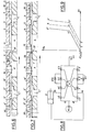
- FIGs 8 to 15 show another embodiment of the invention.
- the C 40 spring is here deleted and the reaction corresponding to the third zone 2-3 of the characteristic curve is controlled by an additional throttling device 4-4 'located between the throttles 1 and 2 (respectively 1' and 2 ' ) of the circuit of FIG. 1, and defined respectively by chamfers 41 and 42 at the level of the separation between the chamber A and the cavity B on the one hand (A 'and B' on the other hand), as shown in the Figure 11 (the rest of the dispenser remaining otherwise identical to that of the previous embodiment).
- FIG. 9 The operation in this case (FIG. 9) is identical to that which precedes, with regard to the initial and driving zones (FIGS. 11 and 12); however, at a given point in the driving area 1-2 (point 2), the chamfer 42 has come close enough to the adjacent edge of the light B 'to come into play, so that from this moment the pressure assistance and reaction pressure are differentiated by the pressure drop which occurs in the constriction thus formed 4 '.
- the chamfer 42 (41) is dimensioned so that the pressure in the chamber C 'increases only slightly in order to stabilize the operation of the system, while the pressure in the chamber A' continues to increase and therefore , at the same time, the assistance pressure ( Figures 13 and 14).
- the throttles 1 and 3 ' close completely while the throttles 2 and 4' (as well as EV) remain ajar to maintain the stability of the system until the moment when the mechanical stop is reached.
Landscapes
- Engineering & Computer Science (AREA)
- Chemical & Material Sciences (AREA)
- Combustion & Propulsion (AREA)
- Transportation (AREA)
- Mechanical Engineering (AREA)
- Power Steering Mechanism (AREA)
- Steering Control In Accordance With Driving Conditions (AREA)
Applications Claiming Priority (2)
| Application Number | Priority Date | Filing Date | Title |
|---|---|---|---|
| ES505158 | 1981-08-04 | ||
| ES505158A ES8205162A1 (es) | 1981-08-04 | 1981-08-04 | Perfeccionamientos en distribuidores fluidodinamicos |
Publications (3)
| Publication Number | Publication Date |
|---|---|
| EP0072731A2 true EP0072731A2 (de) | 1983-02-23 |
| EP0072731A3 EP0072731A3 (en) | 1984-03-28 |
| EP0072731B1 EP0072731B1 (de) | 1986-11-12 |
Family
ID=8482911
Family Applications (1)
| Application Number | Title | Priority Date | Filing Date |
|---|---|---|---|
| EP19820401455 Expired EP0072731B1 (de) | 1981-08-04 | 1982-08-03 | Hydraulischer Verteiler mit Rückwirkung auf die Steuereinrichtung |
Country Status (6)
| Country | Link |
|---|---|
| US (1) | US4465098A (de) |
| EP (1) | EP0072731B1 (de) |
| JP (1) | JPS5849555A (de) |
| AU (1) | AU548013B2 (de) |
| DE (1) | DE3274228D1 (de) |
| ES (1) | ES8205162A1 (de) |
Cited By (10)
| Publication number | Priority date | Publication date | Assignee | Title |
|---|---|---|---|---|
| EP0084487A2 (de) * | 1982-01-14 | 1983-07-27 | Bendix Espana S.A. | Hydraulischer Verteiler mit Rückwirkung auf den Steuerteil |
| EP0112201A2 (de) * | 1982-11-13 | 1984-06-27 | Bendix Espana S.A. | Hydraulischer Verteiler für Servomechanismus mit Rückwirkung auf das Eintrittsorgan |
| EP0145546A2 (de) * | 1983-11-18 | 1985-06-19 | Bendix Espana S.A. | Hydraulischer Verteiler für eine Servoeinrichtung mit Rückwirkung auf das Eingangsglied |
| EP0245794A1 (de) | 1986-05-12 | 1987-11-19 | Nissan Motor Co., Ltd. | Steuerventil für eine Lenkung mit veränderlicher Hilfskraft |
| DE3744313A1 (de) * | 1986-12-27 | 1988-07-07 | Nissan Motor | Variables servolenksystem |
| DE3744314A1 (de) * | 1986-12-27 | 1988-07-07 | Nissan Motor | Variables servolenksystem |
| DE3744319A1 (de) * | 1986-12-27 | 1988-07-07 | Nissan Motor | Variables servolenksystem |
| DE3744351A1 (de) * | 1986-12-27 | 1988-07-07 | Nissan Motor | Servolenkung mit variabler lenkkraftunterstuetzung |
| DE3802904A1 (de) * | 1987-01-30 | 1988-08-11 | Nissan Motor | Servounterstuetzte lenkanlage |
| EP1732799A2 (de) * | 2004-04-05 | 2006-12-20 | R.H. Sheppard Co., Inc. | Steuerventil für einhydraulisches servolenksystem |
Families Citing this family (10)
| Publication number | Priority date | Publication date | Assignee | Title |
|---|---|---|---|---|
| JPS6015265A (ja) * | 1983-07-04 | 1985-01-25 | Toyoda Mach Works Ltd | サ−ボバルブ |
| JPH0657533B2 (ja) * | 1986-09-30 | 1994-08-03 | 日産自動車株式会社 | パワ−ステアリングの油圧制御装置 |
| JP2503218B2 (ja) * | 1986-12-27 | 1996-06-05 | 日産自動車株式会社 | パワ−ステアリングの油圧制御装置 |
| JP2532081B2 (ja) * | 1987-01-30 | 1996-09-11 | 日産自動車株式会社 | パワ−ステアリングの油圧制御装置 |
| DE3802905A1 (de) * | 1987-01-30 | 1988-08-11 | Nissan Motor | Hydraulikfluiddruck-steuersystem zur verwendung mit einer servolenkung |
| JP2532079B2 (ja) * | 1987-01-30 | 1996-09-11 | 日産自動車株式会社 | パワ−ステアリング用ロ−タリ制御弁 |
| JPH0818571B2 (ja) * | 1987-06-29 | 1996-02-28 | 日産自動車株式会社 | パワ−ステアリングの油圧制御装置 |
| US5038878A (en) * | 1988-10-28 | 1991-08-13 | Nissan Motor Co., Ltd. | Variable assist power steering apparatus |
| US4922803A (en) * | 1989-03-17 | 1990-05-08 | Techco Corporation | Four-way valve |
| US5103715A (en) * | 1989-03-17 | 1992-04-14 | Techco Corporation | Power steering system |
Citations (5)
| Publication number | Priority date | Publication date | Assignee | Title |
|---|---|---|---|---|
| FR2435380A1 (fr) * | 1978-09-06 | 1980-04-04 | Zahnradfabrik Friedrichshafen | Distributeur a clapet(s), ferme en position centrale, pour direction assistee |
| EP0011036A2 (de) * | 1978-11-02 | 1980-05-14 | Bendiberica S.A. | Steuereinrichtung für hydraulische Mechanismen |
| GB2041303A (en) * | 1979-01-08 | 1980-09-10 | Bosch Gmbh Robert | Power assisted steering apparatus |
| EP0021970A1 (de) * | 1979-07-02 | 1981-01-07 | Bendiberica S.A. | Steuerventil für ein durch Druckmittel betätigtes System |
| EP0066507A2 (de) * | 1981-05-26 | 1982-12-08 | Bendix Espana S.A. | Hydraulischer Rotationsverteiler für eine hydraulische Antriebseinrichtung |
Family Cites Families (4)
| Publication number | Priority date | Publication date | Assignee | Title |
|---|---|---|---|---|
| JPS52106528A (en) * | 1976-03-03 | 1977-09-07 | Nissan Motor Co Ltd | Steering power control apparatus for power steering system |
| JPS5389133A (en) * | 1977-01-14 | 1978-08-05 | Nissan Motor Co Ltd | Steering force control device for power steering system |
| ES459710A1 (es) * | 1977-06-11 | 1978-04-01 | Bendiberica Sa | Perfeccionamientos en valvulas de mando para servodireccio- nes de vehiculos. |
| ES472088A1 (es) * | 1978-07-27 | 1979-03-16 | Bendiberica Sa | Perfeccionamientos en distribuidores hidraulicos rotativos. |
-
1981
- 1981-08-04 ES ES505158A patent/ES8205162A1/es not_active Expired
-
1982
- 1982-07-26 AU AU86419/82A patent/AU548013B2/en not_active Ceased
- 1982-07-29 US US06/403,231 patent/US4465098A/en not_active Expired - Lifetime
- 1982-08-03 EP EP19820401455 patent/EP0072731B1/de not_active Expired
- 1982-08-03 DE DE8282401455T patent/DE3274228D1/de not_active Expired
- 1982-08-04 JP JP57135287A patent/JPS5849555A/ja active Granted
Patent Citations (5)
| Publication number | Priority date | Publication date | Assignee | Title |
|---|---|---|---|---|
| FR2435380A1 (fr) * | 1978-09-06 | 1980-04-04 | Zahnradfabrik Friedrichshafen | Distributeur a clapet(s), ferme en position centrale, pour direction assistee |
| EP0011036A2 (de) * | 1978-11-02 | 1980-05-14 | Bendiberica S.A. | Steuereinrichtung für hydraulische Mechanismen |
| GB2041303A (en) * | 1979-01-08 | 1980-09-10 | Bosch Gmbh Robert | Power assisted steering apparatus |
| EP0021970A1 (de) * | 1979-07-02 | 1981-01-07 | Bendiberica S.A. | Steuerventil für ein durch Druckmittel betätigtes System |
| EP0066507A2 (de) * | 1981-05-26 | 1982-12-08 | Bendix Espana S.A. | Hydraulischer Rotationsverteiler für eine hydraulische Antriebseinrichtung |
Cited By (17)
| Publication number | Priority date | Publication date | Assignee | Title |
|---|---|---|---|---|
| EP0084487A3 (en) * | 1982-01-14 | 1984-09-05 | Bendiberica S.A. | Hydraulic distributor with reaction on the control member |
| US4512238A (en) * | 1982-01-14 | 1985-04-23 | Bendiberica S.A. | Hydraulic distributor with a reaction biased control member |
| EP0084487A2 (de) * | 1982-01-14 | 1983-07-27 | Bendix Espana S.A. | Hydraulischer Verteiler mit Rückwirkung auf den Steuerteil |
| EP0112201A2 (de) * | 1982-11-13 | 1984-06-27 | Bendix Espana S.A. | Hydraulischer Verteiler für Servomechanismus mit Rückwirkung auf das Eintrittsorgan |
| EP0112201A3 (en) * | 1982-11-13 | 1984-09-12 | Bendiberica S.A. | Hydraulic distributor for a servo mechanism with reaction at the entry organ |
| EP0145546A2 (de) * | 1983-11-18 | 1985-06-19 | Bendix Espana S.A. | Hydraulischer Verteiler für eine Servoeinrichtung mit Rückwirkung auf das Eingangsglied |
| EP0145546A3 (en) * | 1983-11-18 | 1985-12-18 | Bendiberica S.A. | Hydraulic distributor for a servo mechanism with reaction on the input member |
| US4860635A (en) * | 1986-05-12 | 1989-08-29 | Nissan Motor Co., Ltd. | Steering control valve for variable power assist steering system |
| EP0245794A1 (de) | 1986-05-12 | 1987-11-19 | Nissan Motor Co., Ltd. | Steuerventil für eine Lenkung mit veränderlicher Hilfskraft |
| DE3744313A1 (de) * | 1986-12-27 | 1988-07-07 | Nissan Motor | Variables servolenksystem |
| DE3744319A1 (de) * | 1986-12-27 | 1988-07-07 | Nissan Motor | Variables servolenksystem |
| DE3744351A1 (de) * | 1986-12-27 | 1988-07-07 | Nissan Motor | Servolenkung mit variabler lenkkraftunterstuetzung |
| DE3744314A1 (de) * | 1986-12-27 | 1988-07-07 | Nissan Motor | Variables servolenksystem |
| US4862985A (en) * | 1986-12-27 | 1989-09-05 | Nissan Motor Co., Ltd. | Variable assist power steering system with varying power assist with vehicle speed |
| DE3802904A1 (de) * | 1987-01-30 | 1988-08-11 | Nissan Motor | Servounterstuetzte lenkanlage |
| EP1732799A2 (de) * | 2004-04-05 | 2006-12-20 | R.H. Sheppard Co., Inc. | Steuerventil für einhydraulisches servolenksystem |
| EP1732799A4 (de) * | 2004-04-05 | 2007-11-28 | R H Sheppard Co Inc | Steuerventil für einhydraulisches servolenksystem |
Also Published As
| Publication number | Publication date |
|---|---|
| AU8641982A (en) | 1983-02-10 |
| US4465098A (en) | 1984-08-14 |
| ES505158A0 (es) | 1982-06-16 |
| DE3274228D1 (en) | 1987-01-02 |
| AU548013B2 (en) | 1985-11-14 |
| JPH0341383B2 (de) | 1991-06-21 |
| EP0072731A3 (en) | 1984-03-28 |
| ES8205162A1 (es) | 1982-06-16 |
| EP0072731B1 (de) | 1986-11-12 |
| JPS5849555A (ja) | 1983-03-23 |
Similar Documents
| Publication | Publication Date | Title |
|---|---|---|
| EP0072731B1 (de) | Hydraulischer Verteiler mit Rückwirkung auf die Steuereinrichtung | |
| EP0084487B1 (de) | Hydraulischer Verteiler mit Rückwirkung auf den Steuerteil | |
| EP0072311B1 (de) | Hydraulischer Verteiler für Servomotor mit Zurückbringung in Ruhestellung | |
| EP0145546B1 (de) | Hydraulischer Verteiler für eine Servoeinrichtung mit Rückwirkung auf das Eingangsglied | |
| EP0066507B1 (de) | Hydraulischer Rotationsverteiler für eine hydraulische Antriebseinrichtung | |
| EP1010566B1 (de) | Getriebevorrichtung für fahrbare Maschine mit Ventil zur Kontrolle des Kurvenverhaltens | |
| EP0008252B1 (de) | Rotierender hydraulischer Verteiler, insbesondere für hilfskraftverstärkte Lenkungen | |
| EP0633411A1 (de) | Hilfskraftbetätigte Schalteinrichtung für die Gänge eines Schaltgetriebes, insbesondere für ein Kraftfahrzeug | |
| EP0284460A1 (de) | Druckflüssigkeitsmechanismus, Pumpe oder Motor mit mehreren Verdrängungsvolumen | |
| EP0112209B1 (de) | Hydraulischer Verteiler für eine Servoeinrichtung mit begrenzter Reaktion auf das Eingangsglied | |
| EP0007847A1 (de) | Rotierender hydraulischer Verteiler, insbesondere für hilfskraftverstärkte Lenkungen | |
| FR2571002A1 (fr) | Appareil de commande de transmission de puissance notamment pour engins de chantier | |
| EP0919903B1 (de) | Hilfeeinrichtung zur Betätigung eines Hebels | |
| EP0112201B1 (de) | Hydraulischer Verteiler für Servomechanismus mit Rückwirkung auf das Eintrittsorgan | |
| FR2633987A1 (fr) | Circuit hydraulique pour vehicule de travaux | |
| FR2706567A1 (fr) | Soupape hydraulique, notamment pour la commande d'un dispositif d'actionnement hydraulique dans un système de stabilisation de roulis d'un véhicule automobile. | |
| EP0123619B1 (de) | Hydraulischer Rotationsverteiler, insbesondere für die Servolenkvorrichtung eines Kraftfahrzeuges | |
| FR2529524A1 (fr) | Servo-direction pour vehicule automobile, comportant une valve de regulation pour creer une pression de reaction | |
| EP0095415B1 (de) | Rotationshydraulischer Verteiler mit sternförmigem Rotor, insbesondere für Servolenkungsmechanismus | |
| EP0915792B1 (de) | Bremskraftverstärker mit anpassbarer pneumatischer reaktion | |
| EP0202154B1 (de) | Durchlaufkontroll-Servovorrichtung für hydraulische Einrichtung, insbesondere für Kraftfahrzeug-Servolenkung | |
| EP0730538B1 (de) | Bremsvorrichtung mit maskiertem hub und gleichbleibender verstärkung | |
| FR2541216A1 (fr) | Groupe de distributeurs de commande de direction pour vehicule a chenilles | |
| EP0166657A2 (de) | Kompakter Servolenkungsmechanismus | |
| FR2874564A1 (fr) | Dispositif de freinage automobile et vehicule automobile a propulsion electrique equipe d'un tel dispositif de freinage |
Legal Events
| Date | Code | Title | Description |
|---|---|---|---|
| PUAI | Public reference made under article 153(3) epc to a published international application that has entered the european phase |
Free format text: ORIGINAL CODE: 0009012 |
|
| 17P | Request for examination filed |
Effective date: 19820809 |
|
| AK | Designated contracting states |
Designated state(s): DE FR GB IT |
|
| PUAL | Search report despatched |
Free format text: ORIGINAL CODE: 0009013 |
|
| AK | Designated contracting states |
Designated state(s): DE FR GB IT |
|
| ITF | It: translation for a ep patent filed |
Owner name: ING. ZINI MARANESI & C. S.R.L. |
|
| RAP1 | Party data changed (applicant data changed or rights of an application transferred) |
Owner name: BENDIX ESPANA S.A. |
|
| GRAA | (expected) grant |
Free format text: ORIGINAL CODE: 0009210 |
|
| AK | Designated contracting states |
Kind code of ref document: B1 Designated state(s): DE FR GB IT |
|
| REF | Corresponds to: |
Ref document number: 3274228 Country of ref document: DE Date of ref document: 19870102 |
|
| PLBE | No opposition filed within time limit |
Free format text: ORIGINAL CODE: 0009261 |
|
| STAA | Information on the status of an ep patent application or granted ep patent |
Free format text: STATUS: NO OPPOSITION FILED WITHIN TIME LIMIT |
|
| 26N | No opposition filed | ||
| ITTA | It: last paid annual fee | ||
| PGFP | Annual fee paid to national office [announced via postgrant information from national office to epo] |
Ref country code: GB Payment date: 19960710 Year of fee payment: 15 |
|
| PGFP | Annual fee paid to national office [announced via postgrant information from national office to epo] |
Ref country code: FR Payment date: 19960816 Year of fee payment: 15 |
|
| PGFP | Annual fee paid to national office [announced via postgrant information from national office to epo] |
Ref country code: DE Payment date: 19960828 Year of fee payment: 15 |
|
| PG25 | Lapsed in a contracting state [announced via postgrant information from national office to epo] |
Ref country code: GB Free format text: LAPSE BECAUSE OF NON-PAYMENT OF DUE FEES Effective date: 19970803 |
|
| GBPC | Gb: european patent ceased through non-payment of renewal fee |
Effective date: 19970803 |
|
| PG25 | Lapsed in a contracting state [announced via postgrant information from national office to epo] |
Ref country code: FR Free format text: LAPSE BECAUSE OF NON-PAYMENT OF DUE FEES Effective date: 19980430 |
|
| PG25 | Lapsed in a contracting state [announced via postgrant information from national office to epo] |
Ref country code: DE Free format text: LAPSE BECAUSE OF NON-PAYMENT OF DUE FEES Effective date: 19980501 |
|
| REG | Reference to a national code |
Ref country code: FR Ref legal event code: ST |