EP0072681A1 - Assemblage de soupape à diaphragme pour le réglage du débit - Google Patents
Assemblage de soupape à diaphragme pour le réglage du débit Download PDFInfo
- Publication number
- EP0072681A1 EP0072681A1 EP82304281A EP82304281A EP0072681A1 EP 0072681 A1 EP0072681 A1 EP 0072681A1 EP 82304281 A EP82304281 A EP 82304281A EP 82304281 A EP82304281 A EP 82304281A EP 0072681 A1 EP0072681 A1 EP 0072681A1
- Authority
- EP
- European Patent Office
- Prior art keywords
- stem
- valve
- diaphragm
- valve assembly
- neck
- Prior art date
- Legal status (The legal status is an assumption and is not a legal conclusion. Google has not performed a legal analysis and makes no representation as to the accuracy of the status listed.)
- Granted
Links
Images


Classifications
-
- F—MECHANICAL ENGINEERING; LIGHTING; HEATING; WEAPONS; BLASTING
- F16—ENGINEERING ELEMENTS AND UNITS; GENERAL MEASURES FOR PRODUCING AND MAINTAINING EFFECTIVE FUNCTIONING OF MACHINES OR INSTALLATIONS; THERMAL INSULATION IN GENERAL
- F16K—VALVES; TAPS; COCKS; ACTUATING-FLOATS; DEVICES FOR VENTING OR AERATING
- F16K41/00—Spindle sealings
- F16K41/10—Spindle sealings with diaphragm, e.g. shaped as bellows or tube
- F16K41/103—Spindle sealings with diaphragm, e.g. shaped as bellows or tube the diaphragm and the closure member being integrated in one member
-
- F—MECHANICAL ENGINEERING; LIGHTING; HEATING; WEAPONS; BLASTING
- F16—ENGINEERING ELEMENTS AND UNITS; GENERAL MEASURES FOR PRODUCING AND MAINTAINING EFFECTIVE FUNCTIONING OF MACHINES OR INSTALLATIONS; THERMAL INSULATION IN GENERAL
- F16K—VALVES; TAPS; COCKS; ACTUATING-FLOATS; DEVICES FOR VENTING OR AERATING
- F16K7/00—Diaphragm valves or cut-off apparatus, e.g. with a member deformed, but not moved bodily, to close the passage ; Pinch valves
- F16K7/12—Diaphragm valves or cut-off apparatus, e.g. with a member deformed, but not moved bodily, to close the passage ; Pinch valves with flat, dished, or bowl-shaped diaphragm
- F16K7/14—Diaphragm valves or cut-off apparatus, e.g. with a member deformed, but not moved bodily, to close the passage ; Pinch valves with flat, dished, or bowl-shaped diaphragm arranged to be deformed against a flat seat
- F16K7/16—Diaphragm valves or cut-off apparatus, e.g. with a member deformed, but not moved bodily, to close the passage ; Pinch valves with flat, dished, or bowl-shaped diaphragm arranged to be deformed against a flat seat the diaphragm being mechanically actuated, e.g. by screw-spindle or cam
Definitions
- This invention pertains to a valve assembly of a diaphragm valve for controlling fluid flow, particularly although not exclusively a sanitary water valve, otherwise referred to as a faucet or tap.
- Valve assemblies for controlling fluid flow through a valve chamber positioned between an inlet and outlet conduit and adapted for inherent correction of any misalignment between the valve member and the co-operating stationary valve seat disposed in the valve chamber, or to adjust for irregularities in the valve seat itself while avoiding erosion of the valve, are known.
- Some known valve assemblies provide,additionally, that when the valve member is closed and in abutment with the valve seat, it will not further rotate despite continued rotation of the valve stem, thereby to avoid abrasion and erosion.
- a friction ring is also provided, normally, about the valve stem to provide resistance to rotation of the stem and thus a smooth functioning of the assembly rather than a sudden violent response to an abrupt rotation of the faucet handle attached to the stem.
- This friction ring an O-ring normally, forms a sliding seal, as well, between the valve stem and valve housing and is subject to significant erosion and destruction in rotation of the stem to effect a linear movement thereof in the-valve housing:
- an articulated valve stem was developed that permitted omission of the steel swivel insert.
- the stem comprises a main stem, a ball joint and foot member to accommodate any valve seat irregularity, or the like.
- This assembly while providing a more effective mechanism, secures these advantages at a significant increase in size, complexity, and cost due to material and engineering expenses.
- both this and the prior valve assembly include separate stem nut and lock nut components in the valve housing.
- a valve assembly for use with a valve housing having a valve seat surrounding a fluid flow passage, the assembly comprising a valve stem threadedly mounted on a collar for rotatable and axial movement therein, stop means on the stem for limiting its axial movement in the valve closing direction in co-operation with a stop ring disposed about a neck portion of the valve stem in spaced relation thereto and axially spaced from the collar, the end of the stem beyond the stop ring remote from the collar having a radially extended end flange axially located in a swivel bearing cup so as to be freely rotatable relatively thereto, and a valve diaphragm constituted by a closure means mounted on the swivel bearing cup and adapted to be moved axially upon movement of the stem towards or away from a valve seat to open or close the fluid passage, the closure means having an annular flexible member interconnecting it with a sealing ring disposed about the stem, which sealing ring is adapted
- the assembly is used with a valve housing preferably defining a valve chamber positioned between inlet and outlet conduits, the valve assembly including the valve stem, swivel bearing and valve diaphragm mounted in co-operation with a valve seat within the valve housing.
- the valve stem is thus rotatably mounted in the housing to enable the stem to be moved axially towards and away from the valve seat.
- the head of the stem will, in use, be adapted for retention in, and rotation by, a handle and the opposite end or foot of the valve stem is expanded radially and may be continuous with the stem neck which is conveniently provided with a further flange as the stop means for limiting axial movement of the valve stem within the valve assembly.
- the valve stem is externally threaded for engagement and rotation in the collar which is mounted in the faucet valve housing, for axial movement to and away from a valve seat as aforesaid.
- cup-shaped swivel component or washer preferably formed of a hard but resilient plastics, the latter of inherent lubricity in a significantly preferred embodiment.
- This swivel element is adapted to be received in the enveloping terminal portion of the axially flexible and resilient valve diaphragm.
- the diaphragm is preferably formed of a compressible elastomeric composition, its end closure or end cap portion enveloping the end flange of the stem and swivel component and being adapted to seat in fluid sealing engagement on the valve seat when the valve stem is moved to a closed position.
- the diaphragm is expanded at its opposite end to provide the sealing ring secured, in use, to the valve housing.
- end closure and sealing ring portions of the diaphragm Connecting, and integral with, the foregoing end closure and sealing ring portions of the diaphragm is a constricted neck portion which fits loosely about the annular neck of the valve stem, conveniently sloping outwardly at its opposite ends to form the end cap and sealing ring.
- the diaphragm neck is axially resilient, flexible and compressible and the inner diameter of the diaphragm sealing ring is such that when the valve stem bearing the swivel component and diaphragm closure about its foot are moved to a valve open position the annular diaphragm neck collapses and is drawn up into the sealing ring and the end cap is positively lifted from the valve seat, without breaking the mechanical seal effected by the sealing ring with the surrounding valve housing and the stop ring of rigid construction, normally a metal or engineering plastics, positioned about the valve stem and retained in a fixed position within the valve assembly.
- the stop ring has an inner diameter less than that of the further flange formed about the inner length of the valve stem to limit the axial movement of the valve stem and to prevent it from exerting undue compressive force on the diaphragm and its end cap into, and when in, contact with the valve seat; that is, a squeeze effect not in excess of about 45 percent of the thickness of the end closure means when it is compressed.
- valve diaphragm and swivel bearing adapt to, and compensate for thePresence of any irregularity in the surface of the seat or valve and provide for independent rotation of the valve stem with concomitant stationary disposition of the valve in the valve seat when the two are in contact in the closed position of the valve assembly.
- the foregoing assembly provides for simplicity and relative miniaturization in construction with consequent conservation of materials and significant economic advantages; a reduction in the number of parts required, with elimination of a multiplicity of sites for erosion and leakage and the need for careful calibration in manufacture of the components to reduce the likelihood of leakage which tends to occur where a plurality of elements are required to mate with one another.
- the diameter of the valve stem neck which is conveniently cylindrical in conformation, is preferably within a range of from about 65 percent to 85 percent of theinterior diameter of the constructed neck of the diaphragm in its uncompressed unextended state, in a preferred embodiment of the invention.
- the radial space defined by the upper portion of the necked stem and the inside diameter of the stop ring should be no greater than 160 percent of the wall thickness of the diaphragm neck and particularly the intermediate portion of the neck wall that is involuted or convoluted then the diaphragm is in a contracted state.
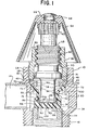
- Figure 1 is a longitudinal sectional view of a valve stem and valve diaphragm and sealing unit mounted in a faucet assembly including a valve chamber and fluid inlet and outlet conduits;
- a valve housing 10 isprovided with an inlet conduit 12 and an outlet conduit 14, connected through a valve chamber 20, an annular valve seat 24 threadedly mounted in the valve housing 10 and adapted to operatein co-operation with the valve assembly 28 to control the flow of a fluid, notably a liquid, and particularly water, through the valve chamber 20 from the inlet 12 to and through the outlet 14.
- a fluid notably a liquid, and particularly water
- the dry stem valve assembly 28 is composed of a valve stem 30, and a swivel bearing or washer 34, a valve diaphragm 38, a metallic stop ring 42, metallic friction washer 46 and a unitary stem nut or collar 48.
- the term "dry stem valve assembly" as employed herein is intended to refer to the isolation of the stem valve from the fluid passing through the valve chamber.
- the valve stem is, however, lubricated as described elsewhere herein. Indeed, the isolation of the stem from the fluid of the valve chamber in accordance with the invention permits retention for an indefinite term of the lubricant fluid in the stem valve assembly.
- the head 50 of the valve stem 30 is splined, or otherwise modified in a manner known to those skilled in the art for attachment to a faucet handle 52 to provide for rotation of.the valve stem 30 in the manner prescribed herein.-
- the faucet handle 52 is otherwise secured to the stem head 50 by a screw 54 received in the threaded interior of the recess 56 axially disposedin the stem head 50 and terminating in the intermediate body 58 of the valve stem 30.
- the annular exterior 60 of the body 58 occurring in spaced relation to the head 50 is threaded.
- the intermediate exterior surface 60 of the valve stem 30 is adapted to threadedly and reciprocably engage the interior upper portion 64 of the stem nut or collar 48.
- the stem nut 48 is also threaded about its exterior lower surface 68 for engagement with the , valve housing 10.
- the stem nut or collar 48 is seated on the friction ring or washer 46 which is, in turn, contiguous with the stop ring 42.
- the stop ring has a sloped outer margin 70, knurled or otherwise serrated, for frictional engagement and seating in the shoulder 72 of the valve housing 10 as shown in Figure 1.
- the threaded portion 60 of the .valve stem 30 also occurs in spaced relation to the radially disposed annular flange 74 along the intermediate axis of the stem body.
- This first or intermediate flange 74 is connected to an annular expanded foot or second terminal flange 76 by a constricted neck 78, of cylindrical conformation, and substantially uniform diameter, in a particularly preferred embodiment.
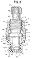
- the swivel 34 mounted in contiguous engagement about the terminal flange or foot 76 is a cup-shaped disc or bearing, the swivel 34, comprising, in the preferred embodiment of the invention shown in Figure 1 to 3 of the drawings, a-bearing surface 82, in contiguous relatonship with the flattened radially extended surface of the.foot 76 and terminating peripherally in the circumferentially disposed upwardly turned rim or lip 84.
- the lip or rim 84 provides the swivel with the capacity to be retained concentrically on the valve stem 30 and irregularities in the engaging rim 86 of the valve seat 24 are absorbed in the valve seating component 90 of the diaphgragm 38.
- the swivel rim 84 in addition to extending upwardly at a right angle to the swivel bearing surface 82, as in the preferred embodiment of Figure 1 to 3, wraps around the curved periphery of the foot 76 in snap-on engagement therewith.
- This embodiment thus requires that therim 84 be resilient in order to snap over the terminal flange 76 so that the swivel or cup 34 is caused to move axially with the stem and yet the swivel 34 is free to rotate on the stem or the stem within the swivel without binding between the stem and swivel.
- the recess is of equivalent annular conformation and diameter and provides a spaced interval between the bearing surface and the terminal flange 76.
- the orifice or recess serves as a lubricant reservoir.
- the diaphragm 38 must be retained in contiguous relation to the bearing surface 82 of the swivel 34 for the orifice to be functional for this purpose.
- the presence of the orifice 88 or a recess serves to reduce the minimal friction existing between the inner bearing surface 82 and lip or rim 84 of the swivel 34 and the stem foot 76 which are, as described elsewhere herein, in abutting relation.
- the lip or rim 84 is adapted to abut a step 104 forming a groove disposed about the periphery of the foot or terminal flange 76, in a particularly preferred embodiment.
- the step 104 and top margin of the rim 84 of the swivel integrate to form a smooth, essentially continuous mating of external surfaces, to avoid abrasion of the interior of the diaphragm at the point of its contraction from the end cap 90 into the neck portion 92 thereof.
- This is particularly significant in the valve stem configuration of Figure 1 to 3 where the step 104 represents the outer peripheral limit of-the stem foot 76; whereas in the embodiment of Figure 4 the step 104 is recessed to accommodate the wrap-around rim 84 of the swivel 34.
- the step 104 is thus constructed as an overhanging component of the stem foot which meets the ascending rim or lip 84 of the swivel 34 as shown in Figure 1 to 3.
- the foregoing lip 84 is disposed in contiguous relation to the straight or substantially straight, vertical side wall 120 of the terminal tip 122 of the foot 76; and the ascending rim 84 of the swivel is, like the adjacent side wall 120 of the stem foot 76, at, or substantially at, right angles to the terminal stem foot surface 124 and swivel bearing surface 126 and inner bearing surface 82 of the swivel 34.
- the swivel of the preferred embodiment is caused to adhere to the stem foot 76 by the enveloping diaphragm 38.
- This bias is enhanced normally by the pressure exerted on the diaphragm by the pressure of the transmitted fluid through the valve chamber when the assembly is in the valve open position. In the closed position, pressure is also exerted on the diaphragm, and consequently the swivel, by contact of the diaphragm with the valve seat.
- the side wall-120 of the terminal extremity or-tip 122 of the stem foot 76 is curved as shown in Figure 4 to receive the wrap-around snap-on rim 84 which, in this embodiment, constitutes a gripping means.
- an orifice 88 in the swivel 34 is further preferred in that this orifice 88 provides clearance for a cut-off teat that is often present on the outer center portion of the stem foot as a result of processing of the valve stem 30 on a screw machine. Where the orifice is not included, and the cut-off teat occurs, the latter must be removed from the axis or center of the foot exterior by a separate operation.
- the valve stem 30 is normally metallic and formed of brass, or less desirably, of aluminium or steel.
- the swivel 34 is formed of a plastics, and more particularly, a thermoplastic resin formulation, and most desirable, one incorporating an acetal copolymer, (including additionally, or in the alternative, a terpolymer) although a thermoplastic polyamide (nylon) may also be employed.
- the polyacetal resin formulation employed herein has an inherent lubricity providing a dynamic coefficient of friction where the plastics is in contact with steel, brass or aluminium within the range of about 0.10 to about 0.35 and preferably about 0.15 as determined.by ASTM Test Method D-1894.
- the preferred acetal copolymer resins for use herein also show a Rockwell Hardness M-scale of about 30 to 85 as measured by ASTM D 785; a flexural strength at 5 percent deformation, using ASTM D 790, of about 10,000 psi to 15,000 psi, and preferably about 13,000 psi; an elongation at -40°F. of 15 percent to 30 percent, and preferably about 20 percent; and, at an ambient temperature of 73°F., of 45 percent to 75 percent and most desirably about 60 percent, employing ASTM D 638 Speed B.
- the preferred acetal resins for use herein are those having a melt index of from about 7 to about 27.
- Polyacetal resins for use in the practice of the present invention are sold under the trademark CELCON by Celanese Corporation, and most desirably CELCON M 90-04, and under the trademark DELRIN by the duPbnt Company of Wilmington Delaware.
- the coefficient of friction of the plastics employed can be even further and significantly reduced by use of an appropriate lubricant such as a conventional silicone concentrate or other standard lubricant oil well known to those skilled in the art, and may be retained in the reservoir 88.
- the swivel 34 permits free rotation of the valve stem 30 with respect to the swivel unit 34.
- This latter unit 34 will remain stationary with respect to any rotary movement of the valve stem 30 and foot 76 when the diaphragm 38, secured to the swivel unit 34, and in turn to the valve housing, as described in detail below, is seated on the valve seat 24.
- the diaphragm 38 in co-operation with the swivel 34, will remain stationary as well, eliminating the significant erosion that would otherwise occur between the diaphragm 38 and valve seat 24 with continued rotation of the valve stem 30 when it is moved in conventional manner to close the valve and eliminate fluid flow through the valve chamber 20.
- Other aspects and advantages of the relationship, construction and composition of the swivel component 34 and valve diaphragm 38 will be evident franhe discussion occurring hereinafter.
- valve diaphragm 38 Disposed about the exterior of the swivel 34, therefore, is the valve diaphragm 38 formed of a resilient, compressible elastomer, such as synthetic or natural rubber, polychloroprene, styrene-butadiene copolymer (GRS, Buna N), polybutadiene, or the like.
- the diaphragm 38 comprises a flattened terminal or seating component or end cap 90 for engaging the rim 86 of the valve seat 24 when the valve assembly is in a closed position.
- the interior surface of the diaphragm end cap or valve 90 abuts the entire, or substantially all of, the niter surface of the swivel 34 and provides a closed end to the bearing orifice 88, where present, and continues in an abutting engagement about the bearing rim 84; so that the terminal end cap seating means 90 is retained in and about the swivel rim 84 as the stem 30 and the integral lower flange or foot 76 contained in the swivel 34 is moved towards or away from the valve seat 24.
- the diaphragm contracts radially from its end cap seating means 90 into a resilient, axially expandable and contractible radially recessed neck 92 that is disposed about and in spaced relation to the corresponding neck 78 of the valve stem 30.
- the valve stem neck 78 and the neck 92 of the diaphragm 38 are disposed in spaced parallel alignment along the intermediate portion of the diaphragm neck 92.
- the valve stem neck 78 has a diameter within the range of about, or precisely, 65 percent to 85 percent, whether in the embodiment Figure 1 to 3 or that of Figure 4 of the drawing, and preferably, about or precisely, 75 percent, of that of.the inside diameter of the diaphragm neck 92 along this intermediate, most radially contracted portion of the diaphragm 38, as determined when the diaphragm is in an unstressed, unextended and uncompressed state.
- the radial space defined by the upper portion of the neck 78 of the valve stem 30 and the inside diameter of the stop ring 42 is, in context with the foregoing diameter relationship, up to, and not in excess of about 160 percent of the wall thickness of the diaphragm neck 92, and particularly the intermediate portion of the diaphragm neck wall that is involuted or convoluted when the diaphragm 90 is in a contracted state.
- This relationship of the stem, diaphragm neck and stop ring prevents the undue involution or collapse of the wall of the diaphragm neck 92 when the diaphragm end cap 90 is withdrawn from the valve seat 24.
- This limitation on the flexure of the diaphragm neck has been found to prevent fracture theredf over an extended period of time when the neck is flexed in response to the pressure occurring in the valve chamber when fluid is passing therethrough.
- the foregoing diameter relationship also permits sufficient flexing of the diaphragm neck to permit a collapsing thereof most efficient to removal of the diaphragm end cap 90 from the valve seat 24 when desired.
- the range in size of the internal diameter of the diaphragm extends from about 0.275 inch to about 0.375 inch; and is more desirably from 0.312 inch to 0.337 . inch; preferably from 0.300 inch to 0.350 inch; and, in a particularly preferred embodiment is about 0.325 inch.
- FIG. 4 The alternative and less preferred embodiment of the diaphragm 90 is shown in Figure 4 wherein the neck 92 of the diaphragm 38, while maintaining a spaced relation to the neck 78 of the valve stem 30, is sloped inwardly toward the axis of the stem at a point intermediate between the sealing ring 94 and the end cap, end closure means of valve 90.
- the diaphragm 38 may, alternately and preferably, assume an intermediate parallel alignment similar to that shown in Figure 1 to 3, as well, and insofar as its radial extension provides a diameter and spatial relationships with respect to the valve stem neck 78 and stop ring 42, such as described hereinabove, and one that is sustained along the length of the diaphragm neck and that of the stem valve, a desirable valve assembly is attained.
- the stem neck may assume a variety of cross-sectional forms, so long as the diameter relationships critical to a significantly superior valve assembly are maintained.
- the employment of polygonal configurations in construction of the stem neck is, for example, avoided so that any tendency toward abrasion of the interior wall of the elastomeric diaphragm neck will.be avoided.
- Figure 1 to 3 illustrates the foregoing preferred embodiment in which the neck 92 of the diaphragm 38, intermediate between its radial expansion at either end and the neck 78 of the valve stem 30 assume a cylindrical construction of uniform or substantially uniform diameter.
- the diaphragm neck 92 expands thereafter, in any event, as noted, in its upward extension in a sloped or conical manner terminating in the radially extended diaphragm sealing ring or rim.
- the inner margin; of the diaphragm sealing rim 94, at its nexus with the outwardly sloping neck 92 has, in a preferred embodiment, a diameter larger than the outer diameter of the terminal seating component or diaphragm end cap 90.
- the sealing ring 94 and end cap 90 are thicker and, as a consequence, more rigid than the diaphragm neck 92. The flexibility of the latter is essential to the bellows-like action to which it is subjected in opening and closure of the diaphragm valve 90 with simultaneous retention in place of the sealing ring 94.
- the end cap portion 90 of the diaphragm 38 does not rotate but moves in a linear or axial direction with the plastics swivel 34 about which it is retained.
- the stem foot 76 rotates with the remainder of the valve stem 30 of which it is an integral part. Protection against rotation, erosion and distortion of the diaphragm 38 is afforded by the swivel 34 which does not rotate.
- the axially constricted and sloped tubular diaphragm neck 92 is drawn up into the passage defined by the lower and inner margin of the stop ring 42, upon which the diaphragm sealing ring or rim 94 is mounted, and the necked portion 78 of the valve stem, when the valve stem 30 is moved away from the valve seat 24 to an open position.
- the diaphragm sealing ring 94 engages and seats upon the metallic stop ring 42 within the sloped knurled border 70 thereof as shown in Figure 3 and upon the radially flat surface 96-thereof as seen particularly in Figure 1 and within the downwardly disposed annular inner shoulder or flange 98 adapted to engage the inner margin of the diaphragm sealing ring 94 and prevent its deformation inwardly with consequent breaking of the seal it provides.
- a metallic friction washer 46 is positioned between the lower terminus of the stem nut 48 and the upper surface of the stop ring 42.
- the outer periphery of the elastomeric sealing ring 94 abuts against the inner wall of the valve housing 10 and is supported in that position by the inwardly directed shoulder 100 of the valve housing 10.
- the sealing ring 94 thus nests in the groove provided by the stop ring 42 atop the sealing ring 94 and, as noted, on its own interior margin by means of the stop rin g 's downwardly disposed flange 98 as well.
- the resilient, compressible, sealing ring 94 secures the nexus of the stop ring 42 and valve housing 10 against leakage of fluid passing through the valve chamber 20.
- the sealing ring 94 prevents rotation of the diaphragm 38 in the valve assembly 28.
- the friction washer 46 permits tightening of the stem nut or collar 48 into the assembly with movement thereof relative to the smooth upper surface of the stop ring 42 without causing the latter to move and abrade the surface of the sealing ring 94 of the diaphragm 38.
- all of the components of the valve assembly are made of hard, rigid material such as, for.example and normally, a metal such as brass, aluminium, steel, nickel, copper or other alloys, engineering plastics or the like known to those skilled in the art.
- the diaphragm sealing ring or rim 94 of the diaphragm 38 in engagement with the stop ring 42 and valve housing 10 thus provides, as noted, the valve assembly 28 with a fluid seal.
- the diaphragm 38 is retained in a stationary position by virtue of the swivel bearing element 34, is protected against the erosion that would be experienced by a conventional O-ring seal, for example, present about the valve stem.
- the O-ring as conventionally disposed, is subject to wear in its slideable engagement with the inner surface of the valve housing in linear and rotational movement of the valve stem through the housing between open and elosed positions.
- the first or intermediate flange 74 of the valve stem 30 serves to define the maximum distance the end cap or valve portion 90 of the diaphragm 38 may be moved, to or away from the rim 86 of the valve seat 24.
- the outer diameter (or at least a portion thereof) of the intermediate flange 74 is made to exceed that of the inner diameter of the threaded upper inner wall 64 of the stem nut or collar 48, so that the lower end of the threaded surface 64 acts as a stop against removal of the valve stem 30 from the valve housing 10 and, specifically, the stem nut 48.
- the radial extent or diameter of the first or intermediate flange 74 also exceeds that of the inner margin of the stop ring 42 so that the valve stem 30 cannot extend in its axial movement beyond a prescribed limit providing for firm, secure engagement of the end cap 90 with the rigid, hard valve seat 24 but without undue stress or compression being exercised on the end cap 90, the valve seat 24, or the other relevant components such as, illustratively, the swivel 34, stem foot 76 or the diaphragm neck 92 thereof.
- the downward movement of the stem is thus limited to that which provides a squeeze or compression of within the range, approximately and preferably precisely, of from 25 percent to 45 percent, and most desirably about :35 percent, of the diaphragm end cap 90 between the valve seat 24 and the swivel 34.
- the physical properties of the elastomer forming the diaphragm 38 are also of material relevance in securing significant advantages.
- the elastomer for use in accordance with the embodiments of the invention has, accordingly, a durometer hardness of from about 65 to 75, and preferably about 70, as measured by a durometer gauge according to ASTM D 2240-68 and read on a Type A scale; and a minimum tensile strength, as determined by ASTM D 412, of 700 psi min. to 2000 psi. min. More desirably, minimum tensile strength will not be less than 1000 psi, and more desirably 1500 psi.
- the elastomer has, in addition, a maximum compression set resistance according to ASTM D 395 Me thod B of up to and not in excess of about 15 percent.
- the frictional engagement between the inner surface of the diaphragm end cap or valve 90.and the outer surface of the swivel 34 be sufficient to retain the swivel in a static or stationary position, that is, in a non- rotational state (without reference to its linear or axial movement) when the valve stem 30 bearing the swivel 34 and diaphragm end cap 90 is rotated to move it towards or away from the valve seat 24.
- the plastics swivel 34 exerts minimal friction, a property necessary to its satisfactory engagement.with the valve stem 30, so that the latter can rotate independently and free of erosion induced by the failure to rotate, of the swivel 34.
- a positive resistance to rotation of the diaphragm end cap 90 and indeed the entire diaphragm 38, and communicated by it to the plastics washer or swivel 34, is that effected by the second primary function of the diaphragm sealing ring 94 in that its positive engagement with the metallic stop ring 42, valve housing 10, and valve housing shoulder 100 pahibits such rotary movement.
- the compressible, resilient character of the end cap 90 is, of course, also essential to an effective fluid seal.
- first or intermediate flange 74 made of metal, preferably, or an engineering plasticsor the like, along the intermediate axis of the stem body 30, in combination with the interior shoulder provided by the stem nut 48 at the upper end and the stop ring 42 both made of metal or material of similar wear-resistant properties, limits the axial movement of the valve stem 30 and, as a consequence, precludes excessive compressive stress from being exerted by the user of the faucet on the elastomeric diaphragm 38, and particularly on its end cap 90, in closing of the valve, preventing undue distortion, stress, dislocation, and rupture of the diaphragm 38, and particularly-its neck portion 92, when the valve is open. Indeed, since a user cannot know when he is inducing excessive torque, stresses of this kind are believed to occur frequently in the use of conventional compression valve assemblies.
- the diaphragm 90 by virtue of its sealing ring 94 engaged between the stop ring 42 and valve housing 10, as described, and the enclosure of the valve stem neck 78 and stem foot 76 by the diaphragm 90 also serves to isolate the valve stem 30 and swivel 34 from contact with the fluid passing through the valve chamber (20) passageway.
- thethreads of the valve stem have conventionally been submerged in the water passageway or valve chamber and the lubricant is readily removed by .the passing fluid; an undesirable effect where, for example, the valve assembly is used to control the supply of drinking water.
- the use of the conventional packing gland or 0-ring to seal the exposed stem and prevent leakage about the faucet handle is obviated.
- the packing gland is normally insufficiently resilient and leaks with age and use, in any event, and the elastomeric O-ring while resilient is, nevertheless, also adapted to rotate with the stem with consequent abrasion and leakage.
- the sealing ring 94 of the diaphragm 38 replaces the foregoing packing gland and O-ring providing a static seal immune from the stresses of rotary movement of the stem.
- the diaphragm thus enjoys a multiple 01 functions, including those of a stem sealant, lubricant retention means and valve closure member.
- a valve structure that meets the most ardous testing standards employed for assessing the reliability of faucets, and particularly those water faucets used in kitchens, bathrooms and the like, including cycle life tests in a hot water environment and portable washer tests, is provided in which the diameter of the stem neck is within the range of about, or precisely, 65 percent to 85 percent of the interior diameter of the intermediate portion of the diaphragm neck; and in which, further, the radial space defined by the upper portion of the necked stem and the inside diameter of the stop ring should be no greater than 160 percent of the wall thickness of the diaphragm neck and particularly the intermediate portion of the neck wall that is involuted or convoluted when the diaphragm is in a contacted state.
- a further provision of material significance in this context is the incorporation in the valve assembly of the overhanging step 104 mating with the vertically disposed rim 84 of the swivel 34.
- a swivel assembly that reduces the complexity and multiplicity of parts; provides for independent rotation of the valve stem when the valve is in sealing engagement with the valve seat to eliminate erosion at the interface of the valve washer and valve seat (without substituting an eroding interaction between the valve and co-operating valve stem); provides for control and removal of the washer from the valve seat by direct operation of the valve stem away from the valve seat and without dependence on the often unpredictable impact and rate of fluid flow from an inlet conduit; and incorporates a sealing ring between the valve housing and stem that avoids the destructive forces of slideable engagement of the sealing ring therebetween.
Applications Claiming Priority (4)
| Application Number | Priority Date | Filing Date | Title |
|---|---|---|---|
| US292527 | 1981-08-13 | ||
| US292595 | 1981-08-13 | ||
| US06/292,595 US4421295A (en) | 1981-08-13 | 1981-08-13 | Valve diaphragm |
| US06/292,527 US4421294A (en) | 1981-08-13 | 1981-08-13 | Valve diaphragm |
Publications (2)
| Publication Number | Publication Date |
|---|---|
| EP0072681A1 true EP0072681A1 (fr) | 1983-02-23 |
| EP0072681B1 EP0072681B1 (fr) | 1986-07-30 |
Family
ID=26967384
Family Applications (1)
| Application Number | Title | Priority Date | Filing Date |
|---|---|---|---|
| EP19820304281 Expired EP0072681B1 (fr) | 1981-08-13 | 1982-08-13 | Assemblage de soupape à diaphragme pour le réglage du débit |
Country Status (2)
| Country | Link |
|---|---|
| EP (1) | EP0072681B1 (fr) |
| DE (1) | DE3272308D1 (fr) |
Cited By (5)
| Publication number | Priority date | Publication date | Assignee | Title |
|---|---|---|---|---|
| US6609698B1 (en) | 2000-10-25 | 2003-08-26 | Arichell Technologies, Inc. | Ferromagnetic/fluid valve actuator |
| WO2004013524A1 (fr) * | 2002-08-06 | 2004-02-12 | Fedegari Autoclavi Spa | Obturateur sanitaire a diaphragme |
| US6752371B2 (en) | 2002-06-19 | 2004-06-22 | Arichell Technologies, Inc. | Valve actuator having small isolated plunger |
| US6948697B2 (en) | 2000-02-29 | 2005-09-27 | Arichell Technologies, Inc. | Apparatus and method for controlling fluid flow |
| IT202000014203A1 (it) * | 2020-06-15 | 2021-12-15 | Rattiinox S R L | Dispositivo di intercettazione di un fluido |
Families Citing this family (1)
| Publication number | Priority date | Publication date | Assignee | Title |
|---|---|---|---|---|
| US20070241298A1 (en) | 2000-02-29 | 2007-10-18 | Kay Herbert | Electromagnetic apparatus and method for controlling fluid flow |
Citations (3)
| Publication number | Priority date | Publication date | Assignee | Title |
|---|---|---|---|---|
| GB977623A (en) * | 1960-08-01 | 1964-12-09 | American Res & Standard Sanita | Improvements in or relating to faucet valve construction |
| AT247088B (de) * | 1958-12-17 | 1966-05-25 | American Radiator & Standard | Ventil |
| FR1495484A (fr) * | 1966-06-09 | 1967-09-22 | Ferodo Sa | Perfectionnements aux robinets assurant la distribution d'un débit de fluide |
-
1982
- 1982-08-13 DE DE8282304281T patent/DE3272308D1/de not_active Expired
- 1982-08-13 EP EP19820304281 patent/EP0072681B1/fr not_active Expired
Patent Citations (3)
| Publication number | Priority date | Publication date | Assignee | Title |
|---|---|---|---|---|
| AT247088B (de) * | 1958-12-17 | 1966-05-25 | American Radiator & Standard | Ventil |
| GB977623A (en) * | 1960-08-01 | 1964-12-09 | American Res & Standard Sanita | Improvements in or relating to faucet valve construction |
| FR1495484A (fr) * | 1966-06-09 | 1967-09-22 | Ferodo Sa | Perfectionnements aux robinets assurant la distribution d'un débit de fluide |
Cited By (7)
| Publication number | Priority date | Publication date | Assignee | Title |
|---|---|---|---|---|
| US6948697B2 (en) | 2000-02-29 | 2005-09-27 | Arichell Technologies, Inc. | Apparatus and method for controlling fluid flow |
| US6609698B1 (en) | 2000-10-25 | 2003-08-26 | Arichell Technologies, Inc. | Ferromagnetic/fluid valve actuator |
| US6752371B2 (en) | 2002-06-19 | 2004-06-22 | Arichell Technologies, Inc. | Valve actuator having small isolated plunger |
| WO2004013524A1 (fr) * | 2002-08-06 | 2004-02-12 | Fedegari Autoclavi Spa | Obturateur sanitaire a diaphragme |
| US7311292B2 (en) | 2002-08-06 | 2007-12-25 | Fedegari Autoclavi Spa | Sanitary diaphragm valve |
| IT202000014203A1 (it) * | 2020-06-15 | 2021-12-15 | Rattiinox S R L | Dispositivo di intercettazione di un fluido |
| WO2021255634A1 (fr) * | 2020-06-15 | 2021-12-23 | Rattiinox S.R.L. | Dispositif d'arrêt de fluide |
Also Published As
| Publication number | Publication date |
|---|---|
| DE3272308D1 (en) | 1986-09-04 |
| EP0072681B1 (fr) | 1986-07-30 |
Similar Documents
| Publication | Publication Date | Title |
|---|---|---|
| US4408745A (en) | Swivel valve | |
| US4421295A (en) | Valve diaphragm | |
| US3495843A (en) | Pressure seal with antiextrusion means | |
| US5129625A (en) | Live load packing system | |
| US6145810A (en) | Aseptic valve construction with diaphragm having straight neck | |
| US5230498A (en) | Live load packing system | |
| US5694975A (en) | Pressure regulator | |
| JP2740154B2 (ja) | 閉止弁向けのステム先端のシール構造体 | |
| US4166606A (en) | Floating seal for fluid control devices | |
| US3211419A (en) | Piston valve with spring pressed head | |
| US4358086A (en) | Butterfly valve | |
| US4815698A (en) | Hard seated valve | |
| JPH09509726A (ja) | 低摩擦パッキン | |
| US3246872A (en) | Seat cup | |
| US3982729A (en) | Back-up seal for diaphragm valve | |
| EP0060620B1 (fr) | Joint de sûreté contre l'incendie pour vanne | |
| EP0072681B1 (fr) | Assemblage de soupape à diaphragme pour le réglage du débit | |
| NO851314L (no) | Anordning med roterbar aksel. | |
| US2895708A (en) | Faucet | |
| US4356998A (en) | Self-closing tap valve | |
| US4368754A (en) | Washerless valve structure particularly for faucets | |
| US4421294A (en) | Valve diaphragm | |
| RU2102645C1 (ru) | Запорный клапан | |
| US6860469B2 (en) | Rotary valve actuator | |
| JPS6231778A (ja) | 流量調節弁 |
Legal Events
| Date | Code | Title | Description |
|---|---|---|---|
| PUAI | Public reference made under article 153(3) epc to a published international application that has entered the european phase |
Free format text: ORIGINAL CODE: 0009012 |
|
| AK | Designated contracting states |
Designated state(s): BE DE FR GB IT NL |
|
| 17P | Request for examination filed |
Effective date: 19830309 |
|
| GRAA | (expected) grant |
Free format text: ORIGINAL CODE: 0009210 |
|
| AK | Designated contracting states |
Kind code of ref document: B1 Designated state(s): BE DE FR GB IT NL |
|
| ITF | It: translation for a ep patent filed |
Owner name: JACOBACCI & PERANI S.P.A. |
|
| ET | Fr: translation filed | ||
| REF | Corresponds to: |
Ref document number: 3272308 Country of ref document: DE Date of ref document: 19860904 |
|
| PLBE | No opposition filed within time limit |
Free format text: ORIGINAL CODE: 0009261 |
|
| STAA | Information on the status of an ep patent application or granted ep patent |
Free format text: STATUS: NO OPPOSITION FILED WITHIN TIME LIMIT |
|
| 26N | No opposition filed | ||
| REG | Reference to a national code |
Ref country code: GB Ref legal event code: 732 |
|
| REG | Reference to a national code |
Ref country code: FR Ref legal event code: GC |
|
| PGFP | Annual fee paid to national office [announced via postgrant information from national office to epo] |
Ref country code: GB Payment date: 19900522 Year of fee payment: 9 |
|
| PGFP | Annual fee paid to national office [announced via postgrant information from national office to epo] |
Ref country code: BE Payment date: 19900613 Year of fee payment: 9 |
|
| PGFP | Annual fee paid to national office [announced via postgrant information from national office to epo] |
Ref country code: FR Payment date: 19900628 Year of fee payment: 9 |
|
| PGFP | Annual fee paid to national office [announced via postgrant information from national office to epo] |
Ref country code: DE Payment date: 19900719 Year of fee payment: 9 |
|
| ITTA | It: last paid annual fee | ||
| PGFP | Annual fee paid to national office [announced via postgrant information from national office to epo] |
Ref country code: NL Payment date: 19900831 Year of fee payment: 9 |
|
| PG25 | Lapsed in a contracting state [announced via postgrant information from national office to epo] |
Ref country code: GB Effective date: 19910813 |
|
| PG25 | Lapsed in a contracting state [announced via postgrant information from national office to epo] |
Ref country code: BE Effective date: 19910831 |
|
| BERE | Be: lapsed |
Owner name: AMERICAN STANDARD INC. Effective date: 19910831 |
|
| PG25 | Lapsed in a contracting state [announced via postgrant information from national office to epo] |
Ref country code: NL Effective date: 19920301 |
|
| GBPC | Gb: european patent ceased through non-payment of renewal fee | ||
| NLV4 | Nl: lapsed or anulled due to non-payment of the annual fee | ||
| PG25 | Lapsed in a contracting state [announced via postgrant information from national office to epo] |
Ref country code: FR Effective date: 19920430 |
|
| PG25 | Lapsed in a contracting state [announced via postgrant information from national office to epo] |
Ref country code: DE Effective date: 19920501 |
|
| REG | Reference to a national code |
Ref country code: FR Ref legal event code: ST |
|
| REG | Reference to a national code |
Ref country code: FR Ref legal event code: RG |