EP0072669A2 - Gun mount - Google Patents
Gun mount Download PDFInfo
- Publication number
- EP0072669A2 EP0072669A2 EP82304251A EP82304251A EP0072669A2 EP 0072669 A2 EP0072669 A2 EP 0072669A2 EP 82304251 A EP82304251 A EP 82304251A EP 82304251 A EP82304251 A EP 82304251A EP 0072669 A2 EP0072669 A2 EP 0072669A2
- Authority
- EP
- European Patent Office
- Prior art keywords
- axis
- gun
- train
- zenith
- elevation
- Prior art date
- Legal status (The legal status is an assumption and is not a legal conclusion. Google has not performed a legal analysis and makes no representation as to the accuracy of the status listed.)
- Granted
Links
- 238000010304 firing Methods 0.000 claims abstract description 9
- 230000007123 defense Effects 0.000 description 4
- 238000010586 diagram Methods 0.000 description 4
- 210000003733 optic disk Anatomy 0.000 description 3
- 230000008878 coupling Effects 0.000 description 2
- 238000010168 coupling process Methods 0.000 description 2
- 238000005859 coupling reaction Methods 0.000 description 2
- 230000003467 diminishing effect Effects 0.000 description 1
- 230000000750 progressive effect Effects 0.000 description 1
- 238000010615 ring circuit Methods 0.000 description 1
Images


Classifications
-
- F—MECHANICAL ENGINEERING; LIGHTING; HEATING; WEAPONS; BLASTING
- F41—WEAPONS
- F41A—FUNCTIONAL FEATURES OR DETAILS COMMON TO BOTH SMALLARMS AND ORDNANCE, e.g. CANNONS; MOUNTINGS FOR SMALLARMS OR ORDNANCE
- F41A27/00—Gun mountings permitting traversing or elevating movement, e.g. gun carriages
- F41A27/06—Mechanical systems
- F41A27/18—Mechanical systems for gun turrets
- F41A27/20—Drives for turret movements
-
- F—MECHANICAL ENGINEERING; LIGHTING; HEATING; WEAPONS; BLASTING
- F41—WEAPONS
- F41A—FUNCTIONAL FEATURES OR DETAILS COMMON TO BOTH SMALLARMS AND ORDNANCE, e.g. CANNONS; MOUNTINGS FOR SMALLARMS OR ORDNANCE
- F41A27/00—Gun mountings permitting traversing or elevating movement, e.g. gun carriages
- F41A27/06—Mechanical systems
- F41A27/08—Bearings, e.g. trunnions; Brakes or blocking arrangements
-
- B—PERFORMING OPERATIONS; TRANSPORTING
- B63—SHIPS OR OTHER WATERBORNE VESSELS; RELATED EQUIPMENT
- B63G—OFFENSIVE OR DEFENSIVE ARRANGEMENTS ON VESSELS; MINE-LAYING; MINE-SWEEPING; SUBMARINES; AIRCRAFT CARRIERS
- B63G1/00—Arrangements of guns or missile launchers; Vessels characterised thereby
-
- F—MECHANICAL ENGINEERING; LIGHTING; HEATING; WEAPONS; BLASTING
- F41—WEAPONS
- F41A—FUNCTIONAL FEATURES OR DETAILS COMMON TO BOTH SMALLARMS AND ORDNANCE, e.g. CANNONS; MOUNTINGS FOR SMALLARMS OR ORDNANCE
- F41A27/00—Gun mountings permitting traversing or elevating movement, e.g. gun carriages
- F41A27/06—Mechanical systems
- F41A27/24—Elevating gear
Definitions
- This invention relates to a mount which provides a gun with three axes of rotation whereby the gun can be pointed both straight up (zenith) and well below horizontal in all directions of azimuth.
- French patent 2,376,394 appears to show a gun for a vehicle mounted on three axes to accommodate side roll of the vehicle.
- U.S. 2,014,762 issued September 17, 1935 to W. W. Fergus also appears to show an antiaircraft mount having three axes.
- Neither patent shows the concept of the three axes having a common intersection with the axis of the gun along which the firing impulse is applied to the mount.
- Other mounts for guns and other deivces, such as telescopes are shown in U.S. 3,001,289 issued September 26, 1961 to V. E. Carbonara; German patent 2,843,943; U.S. 2,178,291 issued October 31, 1939 to G. Steuerlein; and U.S. 483,130 issued September 27, 1892 to F. Bex.
- a two axis gun mount on a fixed, angled base, is shown in "Maritime Defense," Vol. 5, No. 6, June 1980, page 221.
- a feature of this invention is the provision of a three axis gun mount wherein the gun is mounted for movement in elevation and in train (azimuth) with respect to a platform which is disposed in a plane which is at an angle to the horizontal and which platform is mounted for movement about the zenith axis.
- An additional feature of this invention is the provision of such a mount wherein said platform is provided with unlimited rotation in either direction about the zenith axis.
- a yet additional feature of this invention is the provision of such a mount wherein the three axes of the mount, and the axis of the gun along which the firing impulse is applied to the mount, all have a common intersection.
- FIG. 1 is a diagram of certain naval antiair defense requirements. It shows that antiship missiles may make their final approach to the target ship at angles of 20° or less from the zenith. To defeat such a threat, the target ship, in a point defense mode as it rolls from side to side, must be able to fire along the zenith axis, that is, to fire straight up. It is desirable that the target ship be able to fire along any radius within a sphere that is within 120° of the ship's zenith axis, so that it can also fire at more conventional threats along the horizon.
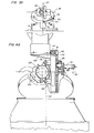
- FIGS. 3A and 3B show a first embodiment of this invention.
- a gun mount 10 is fixed to a nominally horizontal deck 12 which in turn is fixed to a ship. (It will be appreciated that although this invention will be described in a naval environment, it also has utility on terrestial vehicles.)
- a horizontal ring 14 is fixed to the deck 12 and supports a ring bearing 16 on which is journaled the lower surface 18 of a wedge shaped element 20.
- the wedge shaped element 20 is able to rotate without limitation in either direction about the zenith axis 22.
- the upper surface 24 of the element 20 is fixed at an angle of 30° to the lower surface 18.
- the upper surface 24 supports a ring bearing 25 on which is journaled a reference ring 26 which supports a ring bearing 27 on which is journaled the train (azimuth) ring 28.
- the train ring 28 is able to rotate without limitation in either direction about the train (azimuth) axis 30.
- a fixed elevation ring 32 is fixed in a 90° plane to the train ring 28 and rotates with it about the train axis.
- the train ring 28 supports a ring bearing 34 on which is journaled the movable elevation ring 36.
- the ring 36 is able to pivot about the elevation axis 38 from an angle which is parallel to the upper surface 24 of the wedge shaped element 20 through a progressive angle up of 75° to an angle which is 15° below the train (azimuth) axis 30.
- a link 40 is pivotally mounted at its lower end by a ball and socket coupling 42 to the distal end of an arm 44 whose proximal end is fixed to the horizontal ring 14.
- the link 40 is pivotally mounted at its upper end by a ball and socket coupling 46 to the reference ring 26 which is journaled to the train ring 28.
- the rings 26 and 28 always remain in the same plane.
- a gun 50 is mounted by recoil adapters 52 to the movable elevation ring 36.
- the firing gun bore 54 and the recoil adapters lie in a common plane which also includes the zenith and train axes.
- the axis along which the firing impulse is transmitted to the movable elevation ring 36 intersects the zenith and train axes.
- the elevation axis passes through this common plane at the intersection of these axes. With this arrangement the gun firing loads do not create any torque about any of the three axes of rotation.
- the link 40 provides a fixed reference between the reference ring 26 and thereby the plane of the train ring 28, and the fixed horizontal ring 14.
- FIG. 2A shows the elevation coverage of the gun mount.
- FIG. 28 shows a spherical flat pattern which describes how the three axes interact.
- the polar limit of the gun mount as shown is 15° in elevation less than the train (azimuth) axis. This produces a conical blindspot of 30°.
- this blindspot orbits the zenith axis.
- the gun can be pointed at any radius in the sphere from the zenith to 30° below the horizon, i.e., 120° from the zenith.
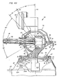
- FIGS. 4A and 48 show a second and preferred embodiment of this invention which substitutes an epicyclic gear train for the reference link 40.
- a gun mount 60 is mounted to a base ring 62 which is fixed to a deck 64.
- the outer race 66 of a three race and gear assembly is fixed to the ring 62.
- the middle race 68 is journaled to the outer race by a plurality of roller bearings 70 and has an integral annular gear 72.
- the inner race 74 is journaled to the middle race by a plurality of roller bearings 76 and has an integral annular gear 78 and an integral annular face gear 80.
- the base 82 of a wedge shaped element 84 is fixed to the middle race 68.
- An outer race 86 is fixed to the upper annulus 88 of the wedge shaped element.
- An innner race 90 is journaled to the outer race by a plurality of roller bearings 92 and has an integral annular face gear 94.
- a fixed elevation outer ring 96 is fixed in a normal plane to a train ring 98 which is fixed to the inner race 90.
- a movable elevation inner ring 100 is journaled to the outer ring 96 by a pair of antifriction bearings 102.
- the ring 100 has an integral annular gear 104, an aft pair of pillow blocks 106 and 108 and a forward pair of upstanding clevises 110 and 112.
- a first drive is provided by a spur gear 114 which is meshed with the gear 72 which rotates the wedge shaped element 84 about the zenith axis 22.
- the gear 114 has an input drive shaft 116 which is journaled for rotation in a bore through the base ring 62.
- a second drive is provided by a spur gear 118, which is meshed with the gear 78, which is integral with the gear 80, which is meshed with a spur gear 120 having an integral shaft 122 which is integral with the spur gear 124 and journaled for rotation in a pillow block 126 fixed to the underside of the base 82 of the wedge shaped element 84.
- the spur gear 124 is meshed with the face gear 94 which is fixed to the train ring 98.
- the gear 118 rotates the train ring 98 about the train (azimuth) axis 30.
- the gear 118 has an input drive shaft 128 which is journaled for rotation in a bore through the base ring 62.
- a third drive is provided by a spur gear 130 which is meshed with the gear 104 which rotates the movable elevation inner ring about the elevation axis.
- the gear 130 is driven by a gear box and an electric motor which are disposed in a housing 131 which is fixed to the fixed elevation ring 96.
- This motor must be coupled to a suitable electrical control circuit by means which will accommodate the movement of the fixed elevation ring 96 with respect to the wedge shaped element 84, and the movement of the wedge shaped element with respect to the base ring 62. This can be provided in the conventional manner by slip rings, not shown.
- a feature of this invention is that the other two drives, i.e., the electrical motors, 116M and 128M, which are coupled to the shafts 116 and 128, may be coupled to their electrical control circuits by fixed wiring since they are stationary with respect to ground.
- a suitable gun 132 here shown as a five barrel gatling type gun, is fixed to the movable elevation inner ring.
- the housing of the gun includes a pair of recoil adapters 134 and 136, having respective spindles 138 and 140, which are respectively mounted to and between the clevis 110 and the block 106 and the clevis 112 and the block 108.
- each barrel in sequence is loaded with a round, locked, fired, unlocked, and the fired case ejected.
- the round is fired at a time when the longitudinal axis of its barrel is in the same plane as the longitudinal axes of the spindles of the recoil adapters.
- Ammunition may be provided to the gun as a belt of linked rounds coming into a stripper-feeder 144 of the gun from a chute 146 which is substantially coaxial with the zenith axis 22.
- the chute may be coupled to a rounds orientation mechanism 148 which is coaxial with the zenith axis. This mechanism permits linked rounds to be fed from a stationary supply notwithstanding unlimited rotation of the gun mount about its zenith axis, or azimuth axis in the case of a two axis gun mount.
- the gun mount may be provided with appropriate fire control mechanism such as a target acquisition radar 150 here shown fixed to a bracket 152 which extends from and is fixed to the movable elevation inner ring 100.
- appropriate fire control mechanism such as a target acquisition radar 150 here shown fixed to a bracket 152 which extends from and is fixed to the movable elevation inner ring 100.
Landscapes
- Engineering & Computer Science (AREA)
- General Engineering & Computer Science (AREA)
- Aiming, Guidance, Guns With A Light Source, Armor, Camouflage, And Targets (AREA)
- Toys (AREA)
- Golf Clubs (AREA)
- Variable-Direction Aerials And Aerial Arrays (AREA)
- Non-Portable Lighting Devices Or Systems Thereof (AREA)
- Pens And Brushes (AREA)
Abstract
Description
- This invention relates to a mount which provides a gun with three axes of rotation whereby the gun can be pointed both straight up (zenith) and well below horizontal in all directions of azimuth.
- French patent 2,376,394 appears to show a gun for a vehicle mounted on three axes to accommodate side roll of the vehicle. U.S. 2,014,762 issued September 17, 1935 to W. W. Fergus also appears to show an antiaircraft mount having three axes. Neither patent shows the concept of the three axes having a common intersection with the axis of the gun along which the firing impulse is applied to the mount. Other mounts for guns and other deivces, such as telescopes, are shown in U.S. 3,001,289 issued September 26, 1961 to V. E. Carbonara; German patent 2,843,943; U.S. 2,178,291 issued October 31, 1939 to G. Steuerlein; and U.S. 483,130 issued September 27, 1892 to F. Bex. A two axis gun mount on a fixed, angled base, is shown in "Maritime Defense," Vol. 5, No. 6, June 1980, page 221.
- It is an object of this invention to provide a mount which can progressively orient a gun along any radius, including zenith, within a portion of a sphere which is greater than a hemisphere.
- It is another object of this invention to provide a three axis gun mount wherein the three axes have a common intersection with the axis of the gun along which the-firing impulse is applied to the mount, thereby precluding gun firing forces from generating torques about any of the axes of rotation.
- It is yet another object of this invention to provide a three axis mount wherein two of the axis drives are referenced to ground, thereby precluding the need for electrical slip rings for these drives.
- It is still another object of this invention to provide a mount which can progressively orient a gun along any radius in a hemisphere without diminishing to zero the train track rate when the longitudinal axis of the gun is parallel to the train axis.
- A feature of this invention is the provision of a three axis gun mount wherein the gun is mounted for movement in elevation and in train (azimuth) with respect to a platform which is disposed in a plane which is at an angle to the horizontal and which platform is mounted for movement about the zenith axis.
- An additional feature of this invention is the provision of such a mount wherein said platform is provided with unlimited rotation in either direction about the zenith axis.
- A yet additional feature of this invention is the provision of such a mount wherein the three axes of the mount, and the axis of the gun along which the firing impulse is applied to the mount, all have a common intersection.
- These and other objects, features and advantages of the invention will be apparent from the following specification thereof taken in conjunction with the accompanying drawing in which:
- FIG. 1 is a diagram of certain naval antiair defense requirements;
- FIG. 2A is a diagram of the coverage in elevation of a gun mount embodying this invention;
- FIG. 2B is a diagram of the coverage in top plan of the gun mount of FIG. 2A;
- FIG. 3A is a view in side elevation of a first embodiment of the gun mount of FIG. 2A;
- FIG. 3B is a view in front elevation of the first embodiment of FIG. 3A;
- FIG. 4A is a view in side elevation of a second embodiment of the gun mount of FIG. 2A; and
- FIG. 48 is a view in rear elevation of the second embodiment of FIG. 4A.
- FIG. 1 is a diagram of certain naval antiair defense requirements. It shows that antiship missiles may make their final approach to the target ship at angles of 20° or less from the zenith. To defeat such a threat, the target ship, in a point defense mode as it rolls from side to side, must be able to fire along the zenith axis, that is, to fire straight up. It is desirable that the target ship be able to fire along any radius within a sphere that is within 120° of the ship's zenith axis, so that it can also fire at more conventional threats along the horizon.
- FIGS. 3A and 3B show a first embodiment of this invention. A
gun mount 10 is fixed to a nominallyhorizontal deck 12 which in turn is fixed to a ship. (It will be appreciated that although this invention will be described in a naval environment, it also has utility on terrestial vehicles.) Ahorizontal ring 14 is fixed to thedeck 12 and supports a ring bearing 16 on which is journaled thelower surface 18 of a wedge shaped element 20. The wedge shaped element 20 is able to rotate without limitation in either direction about thezenith axis 22. Theupper surface 24 of the element 20 is fixed at an angle of 30° to thelower surface 18. Theupper surface 24 supports a ring bearing 25 on which is journaled areference ring 26 which supports a ring bearing 27 on which is journaled the train (azimuth)ring 28. Thetrain ring 28 is able to rotate without limitation in either direction about the train (azimuth)axis 30. Afixed elevation ring 32 is fixed in a 90° plane to thetrain ring 28 and rotates with it about the train axis. Thetrain ring 28 supports a ring bearing 34 on which is journaled themovable elevation ring 36. Thering 36 is able to pivot about theelevation axis 38 from an angle which is parallel to theupper surface 24 of the wedge shaped element 20 through a progressive angle up of 75° to an angle which is 15° below the train (azimuth)axis 30. Alink 40 is pivotally mounted at its lower end by a ball andsocket coupling 42 to the distal end of anarm 44 whose proximal end is fixed to thehorizontal ring 14. Thelink 40 is pivotally mounted at its upper end by a ball andsocket coupling 46 to thereference ring 26 which is journaled to thetrain ring 28. Therings gun 50 is mounted byrecoil adapters 52 to themovable elevation ring 36. The firing gun bore 54 and the recoil adapters lie in a common plane which also includes the zenith and train axes. The axis along which the firing impulse is transmitted to themovable elevation ring 36 intersects the zenith and train axes. The elevation axis passes through this common plane at the intersection of these axes. With this arrangement the gun firing loads do not create any torque about any of the three axes of rotation. Thelink 40 provides a fixed reference between thereference ring 26 and thereby the plane of thetrain ring 28, and the fixedhorizontal ring 14. - FIG. 2A shows the elevation coverage of the gun mount.
- FIG. 28 shows a spherical flat pattern which describes how the three axes interact. The polar limit of the gun mount as shown is 15° in elevation less than the train (azimuth) axis. This produces a conical blindspot of 30°. As the wedge shaped element 20 rotates about the zenith axis, this blindspot orbits the zenith axis. With this blindspot so movable, the gun can be pointed at any radius in the sphere from the zenith to 30° below the horizon, i.e., 120° from the zenith.
- Versatility is available in controlling the movement of the gun mount since there are multiple angular orientations for each of the three axes for any desired one orientation of the gun. A very practical advantage is that the drive for the wedge shaped element and the drive for the train (azimuth) ring are referenced to ground, thereby eliminating electrical slip ring circuits for the zenith axis and train (azimuth) axis rotation.
- FIGS. 4A and 48 show a second and preferred embodiment of this invention which substitutes an epicyclic gear train for the
reference link 40. - A
gun mount 60 is mounted to abase ring 62 which is fixed to adeck 64. Theouter race 66 of a three race and gear assembly is fixed to thering 62. Themiddle race 68 is journaled to the outer race by a plurality ofroller bearings 70 and has an integral annular gear 72. Theinner race 74 is journaled to the middle race by a plurality ofroller bearings 76 and has an integralannular gear 78 and an integral annular face gear 80. Thebase 82 of a wedge shapedelement 84 is fixed to themiddle race 68. Anouter race 86 is fixed to theupper annulus 88 of the wedge shaped element. Aninnner race 90 is journaled to the outer race by a plurality ofroller bearings 92 and has an integralannular face gear 94. A fixed elevationouter ring 96 is fixed in a normal plane to atrain ring 98 which is fixed to theinner race 90. A movable elevationinner ring 100 is journaled to theouter ring 96 by a pair ofantifriction bearings 102. Thering 100 has an integral annular gear 104, an aft pair of pillow blocks 106 and 108 and a forward pair ofupstanding clevises - A first drive is provided by a
spur gear 114 which is meshed with the gear 72 which rotates the wedge shapedelement 84 about thezenith axis 22. Thegear 114 has aninput drive shaft 116 which is journaled for rotation in a bore through thebase ring 62. - A second drive is provided by a
spur gear 118, which is meshed with thegear 78, which is integral with the gear 80, which is meshed with aspur gear 120 having anintegral shaft 122 which is integral with thespur gear 124 and journaled for rotation in apillow block 126 fixed to the underside of thebase 82 of the wedge shapedelement 84. Thespur gear 124 is meshed with theface gear 94 which is fixed to thetrain ring 98. Thus thespur gear 118 rotates thetrain ring 98 about the train (azimuth)axis 30. Thegear 118 has aninput drive shaft 128 which is journaled for rotation in a bore through thebase ring 62. - A third drive is provided by a
spur gear 130 which is meshed with the gear 104 which rotates the movable elevation inner ring about the elevation axis. Thegear 130 is driven by a gear box and an electric motor which are disposed in ahousing 131 which is fixed to the fixedelevation ring 96. This motor must be coupled to a suitable electrical control circuit by means which will accommodate the movement of the fixedelevation ring 96 with respect to the wedge shapedelement 84, and the movement of the wedge shaped element with respect to thebase ring 62. This can be provided in the conventional manner by slip rings, not shown. A feature of this invention is that the other two drives, i.e., the electrical motors, 116M and 128M, which are coupled to theshafts - A
suitable gun 132, here shown as a five barrel gatling type gun, is fixed to the movable elevation inner ring. The housing of the gun includes a pair ofrecoil adapters respective spindles clevis 110 and theblock 106 and theclevis 112 and theblock 108. As the cluster ofgun barrels 132 rotates, each barrel in sequence is loaded with a round, locked, fired, unlocked, and the fired case ejected. The round is fired at a time when the longitudinal axis of its barrel is in the same plane as the longitudinal axes of the spindles of the recoil adapters. - Ammunition may be provided to the gun as a belt of linked rounds coming into a stripper-
feeder 144 of the gun from achute 146 which is substantially coaxial with thezenith axis 22. The chute may be coupled to arounds orientation mechanism 148 which is coaxial with the zenith axis. This mechanism permits linked rounds to be fed from a stationary supply notwithstanding unlimited rotation of the gun mount about its zenith axis, or azimuth axis in the case of a two axis gun mount. - The gun mount may be provided with appropriate fire control mechanism such as a
target acquisition radar 150 here shown fixed to abracket 152 which extends from and is fixed to the movable elevationinner ring 100.
Claims (8)
Applications Claiming Priority (2)
| Application Number | Priority Date | Filing Date | Title |
|---|---|---|---|
| US06/293,716 US4437384A (en) | 1981-08-17 | 1981-08-17 | Gun mount |
| US293716 | 1999-04-16 |
Publications (3)
| Publication Number | Publication Date |
|---|---|
| EP0072669A2 true EP0072669A2 (en) | 1983-02-23 |
| EP0072669A3 EP0072669A3 (en) | 1983-05-04 |
| EP0072669B1 EP0072669B1 (en) | 1987-01-21 |
Family
ID=23130256
Family Applications (1)
| Application Number | Title | Priority Date | Filing Date |
|---|---|---|---|
| EP82304251A Expired EP0072669B1 (en) | 1981-08-17 | 1982-08-11 | Gun mount |
Country Status (9)
| Country | Link |
|---|---|
| US (1) | US4437384A (en) |
| EP (1) | EP0072669B1 (en) |
| JP (1) | JPS5875697A (en) |
| KR (1) | KR890000774B1 (en) |
| CA (1) | CA1181276A (en) |
| DE (1) | DE3275232D1 (en) |
| ES (1) | ES515077A0 (en) |
| IL (1) | IL66466A (en) |
| NO (1) | NO155263C (en) |
Cited By (6)
| Publication number | Priority date | Publication date | Assignee | Title |
|---|---|---|---|---|
| FR2662788A1 (en) * | 1990-05-31 | 1991-12-06 | France Etat Armement | Mounting of a turret and of its offset observation system without a blind angle |
| GB2248599A (en) * | 1990-10-10 | 1992-04-15 | Sous Chef Ltd | Filling and sealing sterilised containers |
| GR980100049A (en) * | 1997-02-19 | 1998-10-30 | Buck Werke Gbmh & Co | Arrangement for multiple launches of missiles from the shoulder |
| US6609542B2 (en) | 1998-03-18 | 2003-08-26 | Visy Films And Laminates Pty Limited | Tote bins |
| EP1671882A2 (en) | 2004-12-15 | 2006-06-21 | Blohm + Voss GmbH | Ship with foundations for equipment elements |
| EP1842770A3 (en) * | 2006-04-05 | 2008-03-05 | Oto Melara S.p.A. | Articulated platform for a turret |
Families Citing this family (9)
| Publication number | Priority date | Publication date | Assignee | Title |
|---|---|---|---|---|
| IT8353861U1 (en) * | 1983-10-26 | 1985-04-26 | Costr Aeronautiche Giovanni Agusta Spa | PORTABLE WEAPON FOR AIRCRAFT, ESPECIALLY HELICOPTERS |
| US4662263A (en) * | 1984-12-05 | 1987-05-05 | General Electric Company | Ammunition feed system interface |
| US4635529A (en) * | 1984-12-21 | 1987-01-13 | General Electric Company | Seal assembly |
| EP0405177A1 (en) * | 1989-06-30 | 1991-01-02 | Werkzeugmaschinenfabrik Oerlikon-Bührle AG | Device for feeding with cartridges a gun which is moveable in elevation |
| CH693687A5 (en) * | 1999-06-10 | 2003-12-15 | Contraves Ag | Mount, launcher with a launching tube assembly and a carriage, ammunition containers for carriage with launching tube assembly and use of the launcher. |
| FR2852385B1 (en) * | 2003-03-13 | 2005-06-03 | Giat Ind Sa | MULTITUBE TURRET FOR HIGH ENERGY MUNITION |
| KR101237602B1 (en) * | 2010-05-19 | 2013-02-26 | 정인 | automatic correction apparatus for trajectory of a projectile and correction method using the same |
| KR101508625B1 (en) * | 2013-11-14 | 2015-04-08 | 삼성중공업 주식회사 | Apparatus and method for assembling bearing |
| KR101516163B1 (en) * | 2013-11-15 | 2015-05-04 | 삼성중공업 주식회사 | Assembling method shaft structure of wind turbine |
Family Cites Families (11)
| Publication number | Priority date | Publication date | Assignee | Title |
|---|---|---|---|---|
| US483130A (en) | 1892-09-27 | Means for operating heavy ordnance | ||
| US2014762A (en) | 1934-02-28 | 1935-09-17 | William W Fergus | Antiaircraft gun |
| GB464543A (en) | 1935-05-29 | 1937-04-20 | Precision Moderne | Improvements in machine-gun mountings |
| GB515993A (en) | 1936-03-27 | 1937-06-29 | Blackburn Aircraft Ltd | Improvements in and relating to the mounting of guns and other similarly mounted instruments, more particularly those used in aircraft |
| US2178291A (en) | 1936-06-10 | 1939-10-31 | Messerschmitt Boelkow Blohm | Gun mount for aircraft |
| FR836197A (en) | 1938-04-05 | 1939-01-12 | Siemens App Und Maschinen Gmbh | Combat post, especially for aircraft |
| US2712271A (en) * | 1949-05-07 | 1955-07-05 | Richard E Wabnitz | Adjustable support apparatus |
| US3001289A (en) | 1950-12-19 | 1961-09-26 | Kollsman Instr Corp | Automatic navigator |
| FR2376394A1 (en) | 1977-01-04 | 1978-07-28 | Thomson Brandt | Gun turret for vehicle or ship - has three main swivelling axes to allow for vehicle or ship side tilt or roll |
| CH626163A5 (en) | 1977-11-04 | 1981-10-30 | Oerlikon Buehrle Ag | |
| US4353283A (en) | 1979-08-10 | 1982-10-12 | Roger Crepin | Firing turret for a vehicle, and vehicle including such a turret |
-
1981
- 1981-08-17 US US06/293,716 patent/US4437384A/en not_active Expired - Lifetime
-
1982
- 1982-02-26 CA CA000397264A patent/CA1181276A/en not_active Expired
- 1982-08-04 IL IL66466A patent/IL66466A/en unknown
- 1982-08-11 EP EP82304251A patent/EP0072669B1/en not_active Expired
- 1982-08-11 DE DE8282304251T patent/DE3275232D1/en not_active Expired
- 1982-08-16 NO NO822782A patent/NO155263C/en unknown
- 1982-08-17 ES ES515077A patent/ES515077A0/en active Granted
- 1982-08-17 JP JP57141773A patent/JPS5875697A/en active Granted
- 1982-08-17 KR KR8203693A patent/KR890000774B1/en not_active Expired
Cited By (7)
| Publication number | Priority date | Publication date | Assignee | Title |
|---|---|---|---|---|
| FR2662788A1 (en) * | 1990-05-31 | 1991-12-06 | France Etat Armement | Mounting of a turret and of its offset observation system without a blind angle |
| GB2248599A (en) * | 1990-10-10 | 1992-04-15 | Sous Chef Ltd | Filling and sealing sterilised containers |
| GR980100049A (en) * | 1997-02-19 | 1998-10-30 | Buck Werke Gbmh & Co | Arrangement for multiple launches of missiles from the shoulder |
| US6609542B2 (en) | 1998-03-18 | 2003-08-26 | Visy Films And Laminates Pty Limited | Tote bins |
| EP1671882A2 (en) | 2004-12-15 | 2006-06-21 | Blohm + Voss GmbH | Ship with foundations for equipment elements |
| EP1671882A3 (en) * | 2004-12-15 | 2008-03-05 | Blohm + Voss GmbH | Ship with foundations for equipment elements |
| EP1842770A3 (en) * | 2006-04-05 | 2008-03-05 | Oto Melara S.p.A. | Articulated platform for a turret |
Also Published As
| Publication number | Publication date |
|---|---|
| US4437384A (en) | 1984-03-20 |
| CA1181276A (en) | 1985-01-22 |
| KR840001329A (en) | 1984-04-30 |
| KR890000774B1 (en) | 1989-04-06 |
| ES8309000A1 (en) | 1983-10-01 |
| EP0072669A3 (en) | 1983-05-04 |
| NO155263B (en) | 1986-11-24 |
| NO155263C (en) | 1987-03-04 |
| ES515077A0 (en) | 1983-10-01 |
| DE3275232D1 (en) | 1987-02-26 |
| EP0072669B1 (en) | 1987-01-21 |
| JPH0417357B2 (en) | 1992-03-25 |
| JPS5875697A (en) | 1983-05-07 |
| NO822782L (en) | 1983-02-18 |
| IL66466A (en) | 1987-02-27 |
Similar Documents
| Publication | Publication Date | Title |
|---|---|---|
| US4437384A (en) | Gun mount | |
| US7669513B2 (en) | Multiple weapon system for armored vehicle | |
| US10371479B2 (en) | Stabilized integrated commander's weapon station for combat armored vehicle | |
| US5123327A (en) | Automatic turret tracking apparatus for a light air defense system | |
| US4686888A (en) | Turret system for lightweight military vehicle | |
| US4574685A (en) | Turret system for lightweight military vehicle | |
| US5347910A (en) | Target acquisition system | |
| US7086318B1 (en) | Anti-tank guided missile weapon | |
| US7798050B2 (en) | Quick-response drive mechanism for controlling the movement of an object relative to a support | |
| SE407621B (en) | KORBART WEAPON | |
| US11719500B2 (en) | Ammunition launching device | |
| US4518990A (en) | Observation system for military vehicles | |
| EP2561306A1 (en) | Vehicle comprising a turret mount, an auxiliary mount, and a viewing device arranged on the auxiliary mount | |
| EP1549899B1 (en) | Device for protecting objects against ammunition in the form of guided missiles | |
| US4019422A (en) | Vehicular mounted tow missile system | |
| US4662265A (en) | Arrangement for horizontally orienting a rotatable platform for a weapon | |
| US4587881A (en) | Depression gun pod | |
| US5219133A (en) | Lone attack aircraft defense system | |
| CA1229252A (en) | Turret system for lightweight military vehicle | |
| EP2133647B1 (en) | Weapon platform | |
| EP1671075B1 (en) | Multiple weapon system for an armored vehicle | |
| US20080053300A1 (en) | Gun Mount | |
| US3356150A (en) | Mechanism for deflection of a contrarotating propeller system | |
| US5078044A (en) | Turret comprising a rotating joint and an angular velocity reduction device | |
| US3396629A (en) | Launching posts and the remote control of missiles |
Legal Events
| Date | Code | Title | Description |
|---|---|---|---|
| PUAI | Public reference made under article 153(3) epc to a published international application that has entered the european phase |
Free format text: ORIGINAL CODE: 0009012 |
|
| AK | Designated contracting states |
Designated state(s): CH DE FR GB IT LI NL SE |
|
| PUAL | Search report despatched |
Free format text: ORIGINAL CODE: 0009013 |
|
| AK | Designated contracting states |
Designated state(s): CH DE FR GB IT LI NL SE |
|
| 17P | Request for examination filed |
Effective date: 19831028 |
|
| GRAA | (expected) grant |
Free format text: ORIGINAL CODE: 0009210 |
|
| AK | Designated contracting states |
Kind code of ref document: B1 Designated state(s): CH DE FR GB IT LI NL SE |
|
| REF | Corresponds to: |
Ref document number: 3275232 Country of ref document: DE Date of ref document: 19870226 |
|
| ITF | It: translation for a ep patent filed | ||
| ET | Fr: translation filed | ||
| PLBE | No opposition filed within time limit |
Free format text: ORIGINAL CODE: 0009261 |
|
| STAA | Information on the status of an ep patent application or granted ep patent |
Free format text: STATUS: NO OPPOSITION FILED WITHIN TIME LIMIT |
|
| 26N | No opposition filed | ||
| PGFP | Annual fee paid to national office [announced via postgrant information from national office to epo] |
Ref country code: SE Payment date: 19910718 Year of fee payment: 10 |
|
| PGFP | Annual fee paid to national office [announced via postgrant information from national office to epo] |
Ref country code: GB Payment date: 19910725 Year of fee payment: 10 |
|
| PGFP | Annual fee paid to national office [announced via postgrant information from national office to epo] |
Ref country code: FR Payment date: 19910808 Year of fee payment: 10 |
|
| PGFP | Annual fee paid to national office [announced via postgrant information from national office to epo] |
Ref country code: DE Payment date: 19910822 Year of fee payment: 10 |
|
| PGFP | Annual fee paid to national office [announced via postgrant information from national office to epo] |
Ref country code: NL Payment date: 19910831 Year of fee payment: 10 |
|
| PG25 | Lapsed in a contracting state [announced via postgrant information from national office to epo] |
Ref country code: GB Effective date: 19920811 |
|
| PG25 | Lapsed in a contracting state [announced via postgrant information from national office to epo] |
Ref country code: SE Effective date: 19920812 |
|
| ITTA | It: last paid annual fee | ||
| PG25 | Lapsed in a contracting state [announced via postgrant information from national office to epo] |
Ref country code: NL Effective date: 19930301 |
|
| GBPC | Gb: european patent ceased through non-payment of renewal fee |
Effective date: 19920811 |
|
| NLV4 | Nl: lapsed or anulled due to non-payment of the annual fee | ||
| PG25 | Lapsed in a contracting state [announced via postgrant information from national office to epo] |
Ref country code: FR Effective date: 19930430 |
|
| PG25 | Lapsed in a contracting state [announced via postgrant information from national office to epo] |
Ref country code: DE Effective date: 19930501 |
|
| REG | Reference to a national code |
Ref country code: FR Ref legal event code: ST |
|
| PGFP | Annual fee paid to national office [announced via postgrant information from national office to epo] |
Ref country code: CH Payment date: 19930714 Year of fee payment: 12 |
|
| PG25 | Lapsed in a contracting state [announced via postgrant information from national office to epo] |
Ref country code: LI Effective date: 19940831 Ref country code: CH Effective date: 19940831 |
|
| EUG | Se: european patent has lapsed |
Ref document number: 82304251.0 Effective date: 19930307 |
|
| REG | Reference to a national code |
Ref country code: CH Ref legal event code: PL |