EP0072633A2 - Getreidetrockenanlagen - Google Patents
Getreidetrockenanlagen Download PDFInfo
- Publication number
- EP0072633A2 EP0072633A2 EP82303928A EP82303928A EP0072633A2 EP 0072633 A2 EP0072633 A2 EP 0072633A2 EP 82303928 A EP82303928 A EP 82303928A EP 82303928 A EP82303928 A EP 82303928A EP 0072633 A2 EP0072633 A2 EP 0072633A2
- Authority
- EP
- European Patent Office
- Prior art keywords
- grain
- column
- distributor
- dryer
- bed
- Prior art date
- Legal status (The legal status is an assumption and is not a legal conclusion. Google has not performed a legal analysis and makes no representation as to the accuracy of the status listed.)
- Withdrawn
Links
Images

Classifications
-
- F—MECHANICAL ENGINEERING; LIGHTING; HEATING; WEAPONS; BLASTING
- F26—DRYING
- F26B—DRYING SOLID MATERIALS OR OBJECTS BY REMOVING LIQUID THEREFROM
- F26B17/00—Machines or apparatus for drying materials in loose, plastic, or fluidised form, e.g. granules, staple fibres, with progressive movement
- F26B17/12—Machines or apparatus for drying materials in loose, plastic, or fluidised form, e.g. granules, staple fibres, with progressive movement with movement performed solely by gravity, i.e. the material moving through a substantially vertical drying enclosure, e.g. shaft
- F26B17/14—Machines or apparatus for drying materials in loose, plastic, or fluidised form, e.g. granules, staple fibres, with progressive movement with movement performed solely by gravity, i.e. the material moving through a substantially vertical drying enclosure, e.g. shaft the materials moving through a counter-current of gas
- F26B17/1408—Machines or apparatus for drying materials in loose, plastic, or fluidised form, e.g. granules, staple fibres, with progressive movement with movement performed solely by gravity, i.e. the material moving through a substantially vertical drying enclosure, e.g. shaft the materials moving through a counter-current of gas the gas being supplied and optionally extracted through ducts extending into the moving stack of material
- F26B17/1416—Machines or apparatus for drying materials in loose, plastic, or fluidised form, e.g. granules, staple fibres, with progressive movement with movement performed solely by gravity, i.e. the material moving through a substantially vertical drying enclosure, e.g. shaft the materials moving through a counter-current of gas the gas being supplied and optionally extracted through ducts extending into the moving stack of material the ducts being half open or perforated and arranged horizontally
-
- F—MECHANICAL ENGINEERING; LIGHTING; HEATING; WEAPONS; BLASTING
- F26—DRYING
- F26B—DRYING SOLID MATERIALS OR OBJECTS BY REMOVING LIQUID THEREFROM
- F26B25/00—Details of general application not covered by group F26B21/00 or F26B23/00
- F26B25/001—Handling, e.g. loading or unloading arrangements
- F26B25/002—Handling, e.g. loading or unloading arrangements for bulk goods
Definitions
- the present invention relates to grain dryers and a method of feeding grain into such dryers.
- a concurrent flow hot air dryer grain is fed into the top of a drying column and hot air is passed through the grain bed in the column in the same direction as the grain in the bed continuously flows down the column to a grain outlet.
- a low grain inlet temperature and rapid evaporation of moisture from the grain is required to keep it well below the air temperature and avoid heat damage.
- Moisture can only evaporate rapidly from the grain for a short time, due to the moisture gradients set up in the grain kernels so the time of direct exposure to the hot air must be short.
- any grain is not exposed to the hot air at-the start of drying it will remain wetter than required as it passes down the dryer column.
- a grain dryer comprises a dryer column normally of circular cross section, means for feeding drying air into the top of the column, and means for feeding grain into the top of the column, the grain feed means comprising a distributor rotatably mounted in the dryer so as to distribute grain evenly around the top of a grain bed in an upper part of the column.
- a method of drying grain according to the invention comprises feeding drying air into the top of a dryer column, feeding grain into the top of the dryer column and distributing it evenly around over the top of a grain bed in an upper part of the column.
- the grain is kept separate from the drying air and is thereby kept as cool as possible until it meets the drying air at the entry point to the bed. Virtually all the grain is then exposed, for a short time, to the inlet drying air.
- the grain on the top of the bed can be maintained in a flat level condition so that the air and grain move initially parallel to the column axis which results in uniform treatment of the grain.
- the distributor is provided with an inlet coaxial with the column axis and an outlet or outlets which extend outwards from the inlet axis to or towards the inner periphery of the column.
- the rotation rate may be substantially constant. However in this case if the dryer output rate is appreciably slower than the input rate the grain bed level will tend to rise and grain will tend to build up ahead of the distributor.
- the distributor is preferably provided with a leading surface angled upwardly from the plane of rotation in the direction of rotation and preferably the lower edge of the leading surface of the distributor is higher than the trailing edge. In an experimental model the distributor leading edge was 2 mm higher than the trailing edge and this was satisfactory.
- the speed of rotation of the distributor may be as low tLs 1 to 2 rpm but in an experimental model the speed was satisfactory at 15 rpm. It is therefore considered a speed range of 1-20 rpm is suitable.
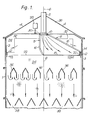
- the dryer shown in Figure 1 has a cylindrical dryer column 1 with an inner wall 2 and an outer wall 3.
- the column has a triangular roof 4 in the centre of which is a grain inlet 5 forming part of means for feeding grain into the top of the column.
- the inlet 5 is coaxial with the column axis 6.
- a rotatable distributor 8 mounted in the upper portion or head of the column and connected to the grain inlet 5 is a rotatable distributor 8 forming part of the grain feed means.
- the distributor 8 is rotatable about a top bearing 10 and has a lower bearing formed by a rail 12 on the inner wall 2 on which rail runs a wheel or roller 14 mounted on the outer wall 20 of the distributor 8.
- the distributor 8 is insulated with a layer of insulation 16 on its top and sides.
- the bottom 18 of the distributor is open between the column axis 6 and the outer wall 20 of the distributor so that grain may be spread evenly out around the top 22 of the grain bed 24 in the column.
- a motor 28 arranged to drive the distributor 8 through a chain or belt 30 at for _ example a constant rate of between 1 and 20 rpm.
- the space 34 above the grain bed 24 has a hot drying air inlet 32 in one side through which hot drying air passes into the space 34 above the top surface 22 of the grain bed 24.
- the drying air which is under pressure passes down through the bed 24 parallel to the axis 6 and is extracted through ducts 36 passing horizontally across the column and through the bed.
- the grain itself also falls down the column around the ducts 36 to outlets 38 towards the bottom of the column where the grain is extracted by suitable means.
- Figures 2 and 3 show a preferred embodiment of distributor shape.
- the distributor 8' shown in Figures 2 and 3 has an opening 18' at the bottom similar to that shown in Figure 1, and is similarly positioned in line with the axis 6' of the dryer column.
- leading edge 44 of the leading wall is bent first parallel with the top surface of the grain bed and then upwardly at an angle of about 20° and finally is turned further up to join a plate 46 which extends back to the wall 42.
- the lower edge 48 of the trailing wall extends downwardly below the surface of the bed so that the outlet opening 18' is at an angle to the top of the bed as can clearly be seen in Figure 3, in the direction of travel of the distributor as indicated by arrow D.
- surfaces surrounding air space 34 above the grain bed 24 are insulated as well as hot air duct or ducts supplying drying air inlet 32 in the interests of heat loss efficiency.
Landscapes
- Engineering & Computer Science (AREA)
- Mechanical Engineering (AREA)
- General Engineering & Computer Science (AREA)
- Drying Of Solid Materials (AREA)
Applications Claiming Priority (2)
| Application Number | Priority Date | Filing Date | Title |
|---|---|---|---|
| GB8125171 | 1981-08-18 | ||
| GB8125171 | 1981-08-18 |
Publications (2)
| Publication Number | Publication Date |
|---|---|
| EP0072633A2 true EP0072633A2 (de) | 1983-02-23 |
| EP0072633A3 EP0072633A3 (de) | 1984-10-17 |
Family
ID=10524013
Family Applications (1)
| Application Number | Title | Priority Date | Filing Date |
|---|---|---|---|
| EP82303928A Withdrawn EP0072633A3 (de) | 1981-08-18 | 1982-07-23 | Getreidetrockenanlagen |
Country Status (4)
| Country | Link |
|---|---|
| EP (1) | EP0072633A3 (de) |
| DK (1) | DK368182A (de) |
| GB (1) | GB2105449B (de) |
| GR (1) | GR76254B (de) |
Cited By (1)
| Publication number | Priority date | Publication date | Assignee | Title |
|---|---|---|---|---|
| DE3836004A1 (de) * | 1987-10-30 | 1989-05-11 | Tatabanyai Banyak Vallalat | Verfahren und vorrichtung zur senkung des feuchtigkeitsgehaltes von kleinkoernigen festen stoffen |
Families Citing this family (1)
| Publication number | Priority date | Publication date | Assignee | Title |
|---|---|---|---|---|
| CA2045032C (en) * | 1991-06-19 | 1993-08-17 | Ronald A. Loyns | Grain dryer |
Family Cites Families (4)
| Publication number | Priority date | Publication date | Assignee | Title |
|---|---|---|---|---|
| US3123234A (en) * | 1964-03-03 | bjerkan | ||
| FR1474209A (fr) * | 1966-02-11 | 1967-03-24 | Séchoir à grains | |
| US3624921A (en) * | 1969-08-12 | 1971-12-07 | Harlan J Easton | Grain drying and storage apparatus |
| US4064638A (en) * | 1976-06-30 | 1977-12-27 | Ciba-Geigy Ag | Apparatus for drying seeds |
-
1982
- 1982-07-23 GB GB08221397A patent/GB2105449B/en not_active Expired
- 1982-07-23 EP EP82303928A patent/EP0072633A3/de not_active Withdrawn
- 1982-08-13 GR GR69038A patent/GR76254B/el unknown
- 1982-08-17 DK DK368182A patent/DK368182A/da not_active Application Discontinuation
Cited By (1)
| Publication number | Priority date | Publication date | Assignee | Title |
|---|---|---|---|---|
| DE3836004A1 (de) * | 1987-10-30 | 1989-05-11 | Tatabanyai Banyak Vallalat | Verfahren und vorrichtung zur senkung des feuchtigkeitsgehaltes von kleinkoernigen festen stoffen |
Also Published As
| Publication number | Publication date |
|---|---|
| GB2105449A (en) | 1983-03-23 |
| GR76254B (de) | 1984-08-04 |
| DK368182A (da) | 1983-02-19 |
| GB2105449B (en) | 1984-11-28 |
| EP0072633A3 (de) | 1984-10-17 |
Similar Documents
| Publication | Publication Date | Title |
|---|---|---|
| US3898745A (en) | Drying apparatus for concentrating solutions | |
| US3771237A (en) | Device for drying damp powders | |
| US5271163A (en) | System for treating flowable materials | |
| US4038021A (en) | Continuous grain drier and method | |
| EP0831287B1 (de) | Belüfteter rotationstrockner | |
| US4954681A (en) | Drying and crystallizing apparatus for granules, which employs a microwave device | |
| EP0072633A2 (de) | Getreidetrockenanlagen | |
| US5207009A (en) | Method and apparatus for increasing dehydrator efficiency | |
| US4854941A (en) | Method and apparatus for drying fine coal | |
| US5992044A (en) | Method and apparatus for drying grain | |
| US4597737A (en) | Method and apparatus for drying or heat treating granular material | |
| US4101337A (en) | Cement manufacture | |
| US486806A (en) | Drier | |
| US1968910A (en) | Drying apparatus and method | |
| US4888882A (en) | Method and apparatus for drying a particulate material such as bark | |
| US1255843A (en) | Drying apparatus. | |
| SU1076720A2 (ru) | Карусельна сушилка | |
| RU2856276C1 (ru) | Автоматизированная карусельная сушилка зерна и семян | |
| US3229383A (en) | Apparatus for drying and simultaneously cooling the white sugar coming from a centrifuge station | |
| US1216555A (en) | Apparatus for granulating and drying sugar. | |
| KR102618073B1 (ko) | 이탈리안라이그라스 종자용 건조 장치 및 방법 | |
| SU367846A1 (ru) | Установка для термообработки кунжутного семени | |
| US333825A (en) | Drier | |
| JPS6236052Y2 (de) | ||
| SU1259993A1 (ru) | Установка дл сушки жидких пищевых материалов с повышенной адгезией в слое инертных тел |
Legal Events
| Date | Code | Title | Description |
|---|---|---|---|
| PUAI | Public reference made under article 153(3) epc to a published international application that has entered the european phase |
Free format text: ORIGINAL CODE: 0009012 |
|
| AK | Designated contracting states |
Designated state(s): AT CH DE FR IT LI NL SE |
|
| PUAL | Search report despatched |
Free format text: ORIGINAL CODE: 0009013 |
|
| AK | Designated contracting states |
Designated state(s): AT CH DE FR IT LI NL SE |
|
| STAA | Information on the status of an ep patent application or granted ep patent |
Free format text: STATUS: THE APPLICATION IS DEEMED TO BE WITHDRAWN |
|
| 18D | Application deemed to be withdrawn |
Effective date: 19850617 |
|
| RIN1 | Information on inventor provided before grant (corrected) |
Inventor name: LAYTON, TERENCE WILLIAM |