EP0072288B1 - Transducteur électroacoustique à polymère piézoélectrique - Google Patents
Transducteur électroacoustique à polymère piézoélectrique Download PDFInfo
- Publication number
- EP0072288B1 EP0072288B1 EP82401393A EP82401393A EP0072288B1 EP 0072288 B1 EP0072288 B1 EP 0072288B1 EP 82401393 A EP82401393 A EP 82401393A EP 82401393 A EP82401393 A EP 82401393A EP 0072288 B1 EP0072288 B1 EP 0072288B1
- Authority
- EP
- European Patent Office
- Prior art keywords
- plate
- casing
- piezoelectric
- resilient plate
- transducer according
- Prior art date
- Legal status (The legal status is an assumption and is not a legal conclusion. Google has not performed a legal analysis and makes no representation as to the accuracy of the status listed.)
- Expired
Links
- 229920000642 polymer Polymers 0.000 title description 12
- 239000003990 capacitor Substances 0.000 claims description 11
- 238000005452 bending Methods 0.000 claims description 10
- 238000013016 damping Methods 0.000 claims description 7
- 230000005611 electricity Effects 0.000 claims description 2
- 230000002441 reversible effect Effects 0.000 claims description 2
- 239000002861 polymer material Substances 0.000 claims 2
- 239000002775 capsule Substances 0.000 description 28
- 239000012528 membrane Substances 0.000 description 19
- 230000035945 sensitivity Effects 0.000 description 16
- 238000010586 diagram Methods 0.000 description 9
- 230000004044 response Effects 0.000 description 9
- 230000000694 effects Effects 0.000 description 8
- 239000002033 PVDF binder Substances 0.000 description 6
- 229920002981 polyvinylidene fluoride Polymers 0.000 description 6
- 230000005540 biological transmission Effects 0.000 description 5
- 238000004519 manufacturing process Methods 0.000 description 5
- 229910052751 metal Inorganic materials 0.000 description 5
- 239000002184 metal Substances 0.000 description 5
- 239000010408 film Substances 0.000 description 4
- 239000010409 thin film Substances 0.000 description 4
- OKTJSMMVPCPJKN-UHFFFAOYSA-N Carbon Chemical compound [C] OKTJSMMVPCPJKN-UHFFFAOYSA-N 0.000 description 3
- ZMXDDKWLCZADIW-UHFFFAOYSA-N N,N-Dimethylformamide Chemical compound CN(C)C=O ZMXDDKWLCZADIW-UHFFFAOYSA-N 0.000 description 3
- 230000009471 action Effects 0.000 description 3
- 230000007547 defect Effects 0.000 description 3
- 239000000463 material Substances 0.000 description 3
- 238000000034 method Methods 0.000 description 3
- 239000002245 particle Substances 0.000 description 3
- NLKNQRATVPKPDG-UHFFFAOYSA-M potassium iodide Chemical compound [K+].[I-] NLKNQRATVPKPDG-UHFFFAOYSA-M 0.000 description 3
- PXHVJJICTQNCMI-UHFFFAOYSA-N Nickel Chemical compound [Ni] PXHVJJICTQNCMI-UHFFFAOYSA-N 0.000 description 2
- 239000011230 binding agent Substances 0.000 description 2
- 229910052799 carbon Inorganic materials 0.000 description 2
- 230000008859 change Effects 0.000 description 2
- 238000007906 compression Methods 0.000 description 2
- 238000010276 construction Methods 0.000 description 2
- 230000008878 coupling Effects 0.000 description 2
- 238000010168 coupling process Methods 0.000 description 2
- 238000005859 coupling reaction Methods 0.000 description 2
- 238000011049 filling Methods 0.000 description 2
- 239000006260 foam Substances 0.000 description 2
- 238000010438 heat treatment Methods 0.000 description 2
- 239000010410 layer Substances 0.000 description 2
- 238000003754 machining Methods 0.000 description 2
- 238000001465 metallisation Methods 0.000 description 2
- 230000036961 partial effect Effects 0.000 description 2
- 230000010287 polarization Effects 0.000 description 2
- 229920005597 polymer membrane Polymers 0.000 description 2
- 230000000284 resting effect Effects 0.000 description 2
- 239000004753 textile Substances 0.000 description 2
- XLYOFNOQVPJJNP-UHFFFAOYSA-N water Substances O XLYOFNOQVPJJNP-UHFFFAOYSA-N 0.000 description 2
- BQCIDUSAKPWEOX-UHFFFAOYSA-N 1,1-Difluoroethene Chemical compound FC(F)=C BQCIDUSAKPWEOX-UHFFFAOYSA-N 0.000 description 1
- 241000782128 Albizia adianthifolia Species 0.000 description 1
- RYGMFSIKBFXOCR-UHFFFAOYSA-N Copper Chemical compound [Cu] RYGMFSIKBFXOCR-UHFFFAOYSA-N 0.000 description 1
- 244000043261 Hevea brasiliensis Species 0.000 description 1
- 229910018487 Ni—Cr Inorganic materials 0.000 description 1
- 229920000297 Rayon Polymers 0.000 description 1
- 239000011358 absorbing material Substances 0.000 description 1
- 229910052782 aluminium Inorganic materials 0.000 description 1
- XAGFODPZIPBFFR-UHFFFAOYSA-N aluminium Chemical compound [Al] XAGFODPZIPBFFR-UHFFFAOYSA-N 0.000 description 1
- 239000012736 aqueous medium Substances 0.000 description 1
- 230000008901 benefit Effects 0.000 description 1
- 230000015572 biosynthetic process Effects 0.000 description 1
- 230000000903 blocking effect Effects 0.000 description 1
- 239000006229 carbon black Substances 0.000 description 1
- 238000006243 chemical reaction Methods 0.000 description 1
- RZVXOCDCIIFGGH-UHFFFAOYSA-N chromium gold Chemical compound [Cr].[Au] RZVXOCDCIIFGGH-UHFFFAOYSA-N 0.000 description 1
- VNNRSPGTAMTISX-UHFFFAOYSA-N chromium nickel Chemical compound [Cr].[Ni] VNNRSPGTAMTISX-UHFFFAOYSA-N 0.000 description 1
- 239000011248 coating agent Substances 0.000 description 1
- 238000000576 coating method Methods 0.000 description 1
- 238000004891 communication Methods 0.000 description 1
- 229920001940 conductive polymer Polymers 0.000 description 1
- 235000014510 cooky Nutrition 0.000 description 1
- 229920001577 copolymer Polymers 0.000 description 1
- 229910052802 copper Inorganic materials 0.000 description 1
- 239000010949 copper Substances 0.000 description 1
- 238000002788 crimping Methods 0.000 description 1
- 230000007423 decrease Effects 0.000 description 1
- 230000001419 dependent effect Effects 0.000 description 1
- 230000004069 differentiation Effects 0.000 description 1
- 238000009792 diffusion process Methods 0.000 description 1
- 239000006185 dispersion Substances 0.000 description 1
- 238000005553 drilling Methods 0.000 description 1
- 238000001035 drying Methods 0.000 description 1
- 238000001704 evaporation Methods 0.000 description 1
- 230000008020 evaporation Effects 0.000 description 1
- 238000002474 experimental method Methods 0.000 description 1
- 230000002349 favourable effect Effects 0.000 description 1
- 239000011810 insulating material Substances 0.000 description 1
- 150000002500 ions Chemical class 0.000 description 1
- 229920000126 latex Polymers 0.000 description 1
- 239000004816 latex Substances 0.000 description 1
- 238000011068 loading method Methods 0.000 description 1
- 238000005259 measurement Methods 0.000 description 1
- 239000002609 medium Substances 0.000 description 1
- 150000002739 metals Chemical class 0.000 description 1
- 238000002156 mixing Methods 0.000 description 1
- 229920003052 natural elastomer Polymers 0.000 description 1
- 229920001194 natural rubber Polymers 0.000 description 1
- 229910052759 nickel Inorganic materials 0.000 description 1
- 229920001296 polysiloxane Polymers 0.000 description 1
- 229920002635 polyurethane Polymers 0.000 description 1
- 239000004814 polyurethane Substances 0.000 description 1
- 230000008569 process Effects 0.000 description 1
- 239000002964 rayon Substances 0.000 description 1
- 230000002829 reductive effect Effects 0.000 description 1
- 230000000630 rising effect Effects 0.000 description 1
- 238000007665 sagging Methods 0.000 description 1
- 238000007650 screen-printing Methods 0.000 description 1
- 229910052709 silver Inorganic materials 0.000 description 1
- 239000004332 silver Substances 0.000 description 1
- 239000002356 single layer Substances 0.000 description 1
- 238000009987 spinning Methods 0.000 description 1
- 230000003068 static effect Effects 0.000 description 1
- 229920003051 synthetic elastomer Polymers 0.000 description 1
- 238000003856 thermoforming Methods 0.000 description 1
Images


Classifications
-
- H—ELECTRICITY
- H04—ELECTRIC COMMUNICATION TECHNIQUE
- H04R—LOUDSPEAKERS, MICROPHONES, GRAMOPHONE PICK-UPS OR LIKE ACOUSTIC ELECTROMECHANICAL TRANSDUCERS; DEAF-AID SETS; PUBLIC ADDRESS SYSTEMS
- H04R17/00—Piezoelectric transducers; Electrostrictive transducers
- H04R17/02—Microphones
- H04R17/025—Microphones using a piezoelectric polymer
-
- H—ELECTRICITY
- H04—ELECTRIC COMMUNICATION TECHNIQUE
- H04R—LOUDSPEAKERS, MICROPHONES, GRAMOPHONE PICK-UPS OR LIKE ACOUSTIC ELECTROMECHANICAL TRANSDUCERS; DEAF-AID SETS; PUBLIC ADDRESS SYSTEMS
- H04R17/00—Piezoelectric transducers; Electrostrictive transducers
- H04R17/005—Piezoelectric transducers; Electrostrictive transducers using a piezoelectric polymer
Definitions
- the present invention relates to electro-acoustic translators making it possible to convert an acoustic pressure or a pressure gradient into an electrical voltage. It relates more particularly to microphones and hydrophones at pressure or speed in which the conversion of an acoustic vibration into electrical voltage is ensured by a vibrating element made of piezoelectric polymer.
- the voltage induced by piezoelectric effect varies in opposite direction to the interelectrode capacitance so that with a thin film, it is necessary to produce a strong deformation to obtain good sensitivity.
- the mechanical compliance of a thin membrane is high, but the fact of closing the rear face introduces an acoustic capacity which significantly reduces the compliance of the assembly.
- the volume of the housing can be increased, but this solution is often unacceptable due to the size of the microphone.
- the predominant deformation energy is that which corresponds to the tension-compression and since this stress does not change sign with the alternative acoustic pressure, the voltage delivered is mostly rectified.
- mechanical polarization can be provided by creating an overpressure in the housing carrying the membrane. This overpressure can be obtained by means of an elastic cushion. Double frequency operation can be avoided by using a bimorph structure as a vibrating element, which complicates the manufacture of the membranes, but avoids having to provide a prestress.
- the invention provides an electroacoustic transducer comprising a housing closed by an elastic piezoelectric polymer plate embedded between the housing and a clamping piece and comprising at least one curvature, the faces of said plate being provided with electrodes forming a capacitor connected to an impedance adapter circuit mounted in the housing, characterized in that this bending is reversible and is caused by the shape of the recess which exerts bending forces on the plate.
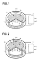
- a microphone capsule with a piezoelectric polymer membrane according to known art. It consists of a two-part casing comprising a bottom 1 and a flange 2. A membrane 3 made of a thin film of piezoelectric polymer is pinched between the flange 2 and the flange of the bottom of the casing 1. This membrane 3 is subjected to the sound pressure p and by deforming it compresses the interior volume of the bottom of the housing 1. If this volume is filled with air at atmospheric pressure, an overpressure ⁇ p produces the sagging indicated in dotted lines in FIG. 1.
- Electrodes 4 and 5 covering the two faces of the membrane 3 make it possible to collect electrical charges induced by the intrinsic piezoelectricity of the film 3.
- An amplifier circuit 7 collects a voltage proportional to these charges and inversely proportional to the apparent dielectric constant of the membrane-electrode assembly. Circuit 7 has a very high input impedance and its output impedance is adapted to the impedance of the transmission line LL. In the presence of an alternating acoustic pressure, the device of FIG. 1 provides a rectified voltage, but the response can be linearized by creating a prestress of the membrane 3.
- the microphone capsule structure shown in FIG. 2 differs from that of FIG. 1 only by the use of a recessed plate 3 of thickness e in place of a membrane. However, this seemingly small difference results in significantly different operation of the piezoelectric transducer.
- a plate Unlike a thin membrane, a plate has a flexural strength which is added to the tensile strength to compensate for the thrust exerted by the pressure p.
- the deformation 6 When the plate is embedded, the deformation 6 has an inflection point on either side from which the curvature is reversed.
- the deformation work is made up of several terms which involve tensile tension, bending moment and shear force. Overall, the mechanical compliance of a plate is lower than that of a membrane, which makes this thicker structure less sensitive to the presence of an interior volume to be compressed.
- the intrinsic piezoelectricity makes it possible to calculate the electric charge induced by stretching of the plate in its plane, but it does not take account of the electric charges induced by bending. It is the bending piezoelectricity, that is to say a piezoelectricity evaluated on the basis of a stress gradient which can account for a good part of the induced electric charge.
- the stress gradient changes sign with each alternation so that the voltage developed between the electrodes 4 and 5 contains an alternating component, without it being necessary to apply a prestress.
- the no-load voltage developed by a piezoelectric plate is higher than that which a membrane would produce, because the electric capacity is lower. This is the reason why a plate is capable of offering, with a lower compliance, a suitable voltage sensitivity and a lower distortion thanks to the linearizing action of the bending piezoelectricity.
- PVF 2 polyvinylidene fluoride
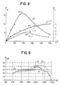
- the diagram in FIG. 8 gives, in the case of a piezoelectric polymer plate PVF 2 having a diameter of 15 mm at embedding, the sensitivity S in millivolt by Pascal and the lowest resonant frequency F in kHz for different thicknesses e expressed in microns.
- Curves 28 and 29 relate to a recessed plate of planar shape.
- Curve 28 shows that the resonance frequency increases linearly with the thickness e of the vibrating plate, which is typical of a structure resistant to bending.
- Curve 29 shows that the voltage sensitivity increases with the thickness e up to 200 microns and that it then decreases for greater thicknesses. The sensitivity measurement is carried out clearly below the resonant frequency, which amounts to making the mass effect of the vibrating plate negligible and to taking an interest in static deformation.
- the frequency F should be considered as illustrative of the frequency band capable of being reproduced faithfully and what curve 29 shows is that up to a thickness of 200 microns the sensitivity and the bandwidth increase simultaneously while 'beyond we are witnessing a common phenomenon in acoustics, namely that the gain achieved on the passband is obtained at the expense of sensitivity.
- the invention provides for systematically creating in the plate a slight curvature taking precedence over all the flatness defects inherent in manufacturing.
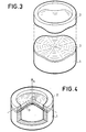
- FIG. 3 an exploded isometric view can be seen of a microphone capsule according to the invention.
- the piezoelectric plate 3 has sectoral corrugations produced by pinching the latter between the corrugated faces of the flange 2 and of the edge of the housing bottom 3. Compared to embedding by pinching a plate as flat as possible between two flat annular spans , there is a significant gain in sensitivity of up to 20 dB. After disassembly and reassembly of the plate 3 in this corrugated type recess, there is good reproducibility of the characteristics of the microphone capsule.
- the undulations of the plate 3 have a favorable impact on the response to tensile-compression stresses whose effect is added to the flexural stresses. Indeed. the curvature of the plate forms a slightly arched structure which reacts linearly to the alternating acoustic pressure.
- Figure 4 shows a partial isometric view of another embodiment of the invention.
- the microphone capsule shown uses a partially domed plate 3 thanks to a slightly conical recess.
- the annular surfaces of the collar 2 and of the bottom of the housing 1 which pinch the plate 3 are portions of coaxial cones whose angle at the top 0 is a little less than 180 °.
- a top angle of 166 ° and a plate 200 microns thick embedded on a diameter of 15 mm a sensitivity of 3.5 millivolts was obtained by Pascal.
- Curves 26 and 27 of the diagram in FIG. 8 were obtained with a frustoconical embedding with an angle at the top equal to 160 °. Curve 26 shows that the voltage sensitivity is significantly higher than that which is obtained with planar embedding. Curve 27 shows that the frequency of the first resonance mode is raised except for very thick layers. The optimum thickness for a polyvinylidene fluoride plate having an internal diameter of 15 mm is around 200 microns.
- FIG. 9 illustrates the frequency response curve of a microphone capsule with a thick vibrating plate of 200 microns.
- Profiles 30 and 31 define the size of a microphone for telephone use.
- the response curve 32 was obtained with acoustic damping of the first plate resonance.
- the dotted curve portion 33 shows the difference in layout when the acoustic damping is not used.
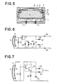
- FIG. 5 is a view in meridian section of a microphone capsule with a piezoelectric plate.
- the housing includes an upper part 2 made of metal which fits into a housing bottom 11 provided with insulated connection terminals 14.
- the piezoelectric plate 3 provided with its metallizations 4 and 5 is embedded frusto-conically between the edge of the upper part 2 of the housing and a metal ring 8 with trapezoidal section.
- the ring 8 is pressed against the plate 3 by an insulating washer 9 resting on an elastic blocking piece 10 which enters a circular slot in the upper part 2 of the housing.
- a pad 12 of sound absorbing material is housed in the central recess of the upper part 2 of the housing. This buffer is wedged between the part 9 and a printed circuit board 11 on which are arranged the electronic components of an electrical impedance adapter circuit.
- the lower limit of the bandwidth is zero if the capacitance that constitutes the plate is connected to an amplifier circuit with infinite input impedance.
- FIG 6 we can see an electrical circuit for ensuring the connection between the microphone capsule 3, 4, 5 and a telephone line LL.
- This circuit uses a unipolar transistor 17 with an insulated gate.
- the source of the transitor 17 is connected by a bias resistor 16 to the ground electrode 4.
- a diode limiter 18 and a decoupling capacitor 19 can be connected in parallel to the resistor to suitably bias the gate of the transistor 17.
- the resistor 15 connected in parallel to the capsule 3, 4, 5 sets the lower cutoff frequency f 2 as indicated above.
- the load resistors 20 and 21 respectively connect the + and - poles of a power source to the electrode 4 and to the drain of the transistor 17.
- Decoupling capacitors 22 prevent the DC component from being transmitted to the line LL .
- the impedance adapter circuit can be produced by means of bipolar transistors as illustrated in the electrical diagram of FIG. 7.
- the transmission line LL can supply the supply voltage to the amplifier stage via a resistor 25 connected to a capacitor filter 24.
- the amplifier stage includes a Darlington circuit 23 with two NPN transistors used as a follower transmitter.
- the resistor 16 plays the role of transmitter load and is connected to the transmission line LL by a connecting capacitor 22.
- the current bias of the Darlington circuit is obtained by a resistor 15 of high value which connects the base of the first transistor NPN of assembly 23 at the positive pole of capacitor 24.
- the microphone capsule itself 3, 4, 5 is connected in parallel to resistor 15.
- FIG. 10 an isometric view can be seen of a piezoelectric plate of a microphone capsule according to the invention. It is an integrated construction in which the polyvinylidene fluoride plate serves as a support for an integrated circuit 34 which groups together the elements 22, 23, 25 and 16 of FIG. 7.
- the metallization 5 is indented and two tabs of connection L are provided for connection to the transmission line.
- the capacitor 24 is externally connected to one of these connection tabs and to the counter-electrode 4.
- the resistor 15 is produced in the form of a dielectric filling 36 made slightly conductive of electricity. Connection 35 connects electrode 5 to the basic connection of the Darlington circuit 23.
- FIG. 11 is a partial and inverted isometric view of the piezoelectric plate of FIG. 10. It can be seen that the production of the resistor connected between the electrodes 4 and 5 is obtained by drilling a hole 36 and filling it with conductive polymer obtained by example with a carbon charge.
- FIG. 12 shows that the resistor connecting the electrodes 4 and 5 can be materialized by a weakly conductive deposit 37 occupying part or all of the edge of the piezoelectric plate 3.
- the leakage resistance 15 of the electrical diagrams of FIGS. 6 and 7 can be obtained by doping in the mass of the piezoelectric polymer. Doping can be carried out by ion diffusion or by mixing traces of potassium iodide with a polymer solution.
- the advantage of this technique is that the time constant is defined intrinsically, therefore independent of the geometric shape of the plate.
- the overload constituted by the presence of the integrated circuit 34 is low compared to the effective mass of the vibrating plate and that the corresponding drop in the resonant frequency is not very marked.
- electrodes 4 and 5 the technique of evaporation under vacuum of metals such as aluminum, nickel-chromium, chromium-gold can be adopted.
- the circular plates can be cut with a cookie cutter from a double-sided metallized sheet.
- conductive particles can be metallic, for example nickel, silver-plated copper, silver, but carbon particles can also be used.
- the polymer used as a binder can be different from the piezoelectric polymer, for example latex, silicones, synthetic or natural rubber.
- the same polymer can also advantageously be used as a binder.
- Corax L product of the DEGUSSA.
- a conductive deposit of this type offers excellent adhesion with PVF 2 and a largely sufficient electrical conductivity. Deposits by screen printing, spinning, brush and projection can be used. Drying takes place at a temperature above 70 ° C to avoid the formation of a powdery deposit.
- FIG. 13 one can see a meridian section of a microphone capsule which is particularly simple to make.
- the upper flange 2 is in contact with a conductive deposit 4 deposited on the convex face of the plate 3; it plays the role of cap and for this purpose, it has a recess 46 communicating with the outside by a series of orifices 38 drilled in the bottom.
- a textile damping washer 39 is glued to the bottom of the recess 46. The external acoustic pressure therefore acts on the convex face of the plate 3 via the orifices 38 and the damping layer 39.
- the concave face of the plate 3 is coated with a conductive deposit 5 in contact with the upper edge of the flange 1.
- the flange 1 has an inner wall pierced with an orifice 42 which establishes a communication between two cavities 47 and 48: A damping textile pad 41 is glued to the orifice 42.
- the cavity 47 is delimited by the concave face of the plate 3 and an upper recess of the flange 1.
- the cavity 48 is delimited by a lower recess of the flange 1 and by a plate 43 of insulating material which carries terminals of connection 45 and the electronic components 44 of an impedance adapter circuit.
- the closure of the microphone capsule is ensured by crimping by means of a metal casing 40 which clamps the flanges 1 and 2 against one another, the plate 3 and the circuit-carrying plate 43.
- the flange 2 serves as an electrode and the casing 40 provides electrostatic shielding.
- the flange 1 is isolated from the casing 40 and is connected to the input of an amplifier.
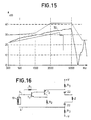
- the response curve 50 of the microphone capsule in FIG. 13 is given in FIG. 15. It can be seen that the shape of this response curve is very regular and well situated within the template imposed for the telephone application.
- FIG. 16 shows the electrical diagram of the impedance adapter circuit used in connection with the microphone capsule 51 of FIG. 13. It comprises two amplifier stages with direct connection.
- the first stage comprises a transistor T, bipolar NPN, the emitter of which is connected to a resistor R 2 having a terminal to ground 4.
- a collector-base resistor R provides current polarization.
- the electrode 5 is connected to the base of the transistor T ,.
- the second amplifier stage comprises a bipolar transistor PNP T 2 , the collector of which is connected to the emitter of transistor T,.
- the base of transistor T 2 is connected to the collector of transistor T, and its emitter is connected via a load resistor R 3 to the positive pole + V of a power source.
- the negative pole - V of the power source is connected to ground 4 via another resistor R 3 .
- the variable voltage drop generated between the emitter of transistor T 2 and ground 4 is transmitted to the transmission line Z by two coupling capacitors 22.
- Figure 14 is an isometric view of a microphone capsule whose piezoelectric plate 3 has a rectangular shape.
- the box 1 has two opposite edges which cooperate with two longitudinal members 2 in order to create a recess having the effect of bending the plate 3.
- the other two edges of the box 1 are upward, in order to frame the non-recessed edges of the plate 3.
- Seals 49 in elastic foam lining the rising edges of the housing 1 isolate the concave face of the plate 3 from the action of the external acoustic pressure.
- the housing 1 has a rigid bottom and at least one internal cavity compressed by the vibration of the plate 3.
- the invention also applies to microphone capsules with a pressure gradient.
- the vibrating plate is embedded in a screen which creates a differentiation between the acoustic pressures acting on the two sides.
- two piezoelectric plates embedded in a frame so as to enclose a volume of air. The electrical interconnection of these plates makes it possible to obtain a pressure gradient type response characteristic, in order to favor close sound sources at the expense of distant sources.
- the microphone described above can advantageously be used as a hydrophone with a first resonance frequency reduced by the water charge.
- the coupling between the vibrating element and the aqueous medium can be done by means of a coating, for example made of polyurethane chosen to have an acoustic impedance close to that of water.
Landscapes
- Physics & Mathematics (AREA)
- Engineering & Computer Science (AREA)
- Acoustics & Sound (AREA)
- Signal Processing (AREA)
- Piezo-Electric Transducers For Audible Bands (AREA)
- Electrostatic, Electromagnetic, Magneto- Strictive, And Variable-Resistance Transducers (AREA)
Applications Claiming Priority (2)
| Application Number | Priority Date | Filing Date | Title |
|---|---|---|---|
| FR8115506A FR2511570A1 (fr) | 1981-08-11 | 1981-08-11 | Transducteur electroacoustique a polymere piezoelectrique |
| FR8115506 | 1981-08-11 |
Publications (3)
| Publication Number | Publication Date |
|---|---|
| EP0072288A2 EP0072288A2 (fr) | 1983-02-16 |
| EP0072288A3 EP0072288A3 (en) | 1983-04-06 |
| EP0072288B1 true EP0072288B1 (fr) | 1986-12-30 |
Family
ID=9261361
Family Applications (1)
| Application Number | Title | Priority Date | Filing Date |
|---|---|---|---|
| EP82401393A Expired EP0072288B1 (fr) | 1981-08-11 | 1982-07-27 | Transducteur électroacoustique à polymère piézoélectrique |
Country Status (7)
| Country | Link |
|---|---|
| US (1) | US4535205A (Sortimente) |
| EP (1) | EP0072288B1 (Sortimente) |
| JP (1) | JPS5840999A (Sortimente) |
| CA (1) | CA1207429A (Sortimente) |
| DE (1) | DE3274945D1 (Sortimente) |
| FR (1) | FR2511570A1 (Sortimente) |
| GB (1) | GB2104345B (Sortimente) |
Families Citing this family (40)
| Publication number | Priority date | Publication date | Assignee | Title |
|---|---|---|---|---|
| US5033093A (en) * | 1990-01-17 | 1991-07-16 | Peavey Electronics Corporation | Compact microphone and method of manufacture |
| FR2542550B1 (fr) * | 1983-03-07 | 1986-11-14 | Thomson Csf | Transducteur electroacoustique a correction acoustique integree |
| FR2542552B1 (fr) * | 1983-03-07 | 1986-04-11 | Thomson Csf | Transducteur electroacoustique a diaphragme piezo-electrique |
| FR2563959B1 (fr) * | 1984-05-04 | 1990-08-10 | Lewiner Jacques | Perfectionnements aux transducteurs electro-acoustiques a electret |
| US4789971A (en) * | 1986-04-07 | 1988-12-06 | The United States Of America As Represented By The Secretary Of The Navy | Broadband, acoustically transparent, nonresonant PVDF hydrophone |
| JPS63131500U (Sortimente) * | 1987-02-20 | 1988-08-29 | ||
| US5125032A (en) * | 1988-12-02 | 1992-06-23 | Erwin Meister | Talk/listen headset |
| EP0381796B1 (de) * | 1989-02-10 | 1995-08-09 | Siemens Aktiengesellschaft | Ultraschall-Sensor |
| US4937555A (en) * | 1989-04-04 | 1990-06-26 | The United States Of America As Represented By The Secretary Of Agriculture | Piezoelectric apparatus and process for detection of insect infestation in an agricultural commodity |
| US5005416A (en) * | 1989-04-04 | 1991-04-09 | The United States Of America As Represented By The Secretary Of Agriculture | Insect detection using a pitfall probe trap having vibration detection |
| GB8924393D0 (en) * | 1989-10-30 | 1989-12-20 | Marconi Co Ltd | Transducer testing |
| DE9114727U1 (de) * | 1991-11-27 | 1993-04-01 | Werma Signalgeräte GmbH, 7201 Rietheim-Weilheim | Piezoelektrischer Summer |
| US5811680A (en) * | 1993-06-13 | 1998-09-22 | Technion Research & Development Foundation Ltd. | Method and apparatus for testing the quality of fruit |
| US5889871A (en) * | 1993-10-18 | 1999-03-30 | The United States Of America As Represented By The Secretary Of The Navy | Surface-laminated piezoelectric-film sound transducer |
| US6049158A (en) * | 1994-02-14 | 2000-04-11 | Ngk Insulators, Ltd. | Piezoelectric/electrostrictive film element having convex diaphragm portions and method of producing the same |
| US5406161A (en) * | 1994-05-24 | 1995-04-11 | Industrial Technology Research Institute | Piezoelectric composite receiver |
| FR2727215B1 (fr) * | 1994-11-18 | 1996-12-20 | Thomson Csf | Dispositif de veille panoramique infrarouge statique a detecteurs matriciels multiples |
| CA2187495A1 (en) * | 1995-10-31 | 1997-05-01 | Dan Charles Plitt | Electronic component assembly and method fhereof |
| US6067363A (en) * | 1996-06-03 | 2000-05-23 | Ericsson Inc. | Audio A/D convertor using frequency modulation |
| FR2750487B1 (fr) * | 1996-06-28 | 2005-10-21 | Thomson Csf | Revetement pour la protection personnelle d'un fantassin |
| US6140740A (en) * | 1997-12-30 | 2000-10-31 | Remon Medical Technologies, Ltd. | Piezoelectric transducer |
| US6463157B1 (en) * | 1998-10-06 | 2002-10-08 | Analytical Engineering, Inc. | Bone conduction speaker and microphone |
| US6347147B1 (en) * | 1998-12-07 | 2002-02-12 | The United States Of America As Represented By The Sceretary Of The Navy | High noise suppression microphone |
| US6222928B1 (en) * | 1999-05-10 | 2001-04-24 | The United States Of America As Represented By The Secretary Of The Navy | Universal impedance matcher for a microphone-to-radio connection |
| WO2001006575A1 (en) * | 1999-07-20 | 2001-01-25 | Sri International | Improved electroactive polymers |
| PT1221180E (pt) * | 1999-07-20 | 2010-11-26 | Stanford Res Inst Int | Polímeros electroactivos |
| EP1421821A4 (en) * | 2001-06-21 | 2006-11-22 | Unconventional Concepts Inc | RATIO SENSORS FOR HEAD-OPERATED CONTACT MICROPHONES |
| WO2003015469A1 (en) * | 2001-08-06 | 2003-02-20 | Measurement Specialties, Inc. | Acoustic sensor using cured piezoelectric film |
| FR2853968B1 (fr) * | 2003-04-17 | 2005-06-24 | Geophysique Cie Gle | Dispositif et procede de mesure d'ondes sismiques |
| SE526743C2 (sv) * | 2003-05-23 | 2005-11-01 | Goeran Ehrlund | Piezoelektrisk mikrofon |
| US7223243B2 (en) * | 2003-11-14 | 2007-05-29 | General Electric Co. | Thin film ultrasonic transmitter/receiver |
| US8369555B2 (en) * | 2006-10-27 | 2013-02-05 | Avago Technologies Wireless Ip (Singapore) Pte. Ltd. | Piezoelectric microphones |
| JP2012527835A (ja) * | 2009-05-18 | 2012-11-08 | ノールズ エレクトロニクス,リミテッド ライアビリティ カンパニー | 低振動感度を有するマイクロホン |
| US8447043B1 (en) | 2009-11-06 | 2013-05-21 | Charles Richard Abbruscato | Piezo element stethoscope |
| US8320576B1 (en) | 2009-11-06 | 2012-11-27 | Charles Richard Abbruscato | Piezo element stethoscope |
| US9185496B1 (en) | 2009-11-06 | 2015-11-10 | Charles Richard Abbruscato | Piezo element stethoscope |
| WO2012112540A2 (en) | 2011-02-15 | 2012-08-23 | Fujifilm Dimatix, Inc. | Piezoelectric transducers using micro-dome arrays |
| US10001574B2 (en) * | 2015-02-24 | 2018-06-19 | Amphenol (Maryland), Inc. | Hermetically sealed hydrophones with very low acceleration sensitivity |
| CN105245984B (zh) * | 2015-10-26 | 2018-01-19 | 苏州登堡电子科技有限公司 | 柱形接触式麦克风 |
| US11051112B2 (en) * | 2018-01-09 | 2021-06-29 | Cirrus Logic, Inc. | Multiple audio transducers driving a display to establish localized quiet zones |
Family Cites Families (9)
| Publication number | Priority date | Publication date | Assignee | Title |
|---|---|---|---|---|
| JPS4975182A (Sortimente) * | 1972-11-20 | 1974-07-19 | ||
| JPS5215972B2 (Sortimente) * | 1974-02-28 | 1977-05-06 | ||
| US4045695A (en) * | 1974-07-15 | 1977-08-30 | Pioneer Electronic Corporation | Piezoelectric electro-acoustic transducer |
| GB1520118A (en) * | 1975-08-11 | 1978-08-02 | Rank Organisation Ltd | Transducers |
| GB1565860A (en) * | 1976-04-02 | 1980-04-23 | Matsushita Electric Industrial Co Ltd | Microphone utilizing high-polymer piezoelectric membrane |
| US4056742A (en) * | 1976-04-30 | 1977-11-01 | Tibbetts Industries, Inc. | Transducer having piezoelectric film arranged with alternating curvatures |
| FR2460485A1 (fr) * | 1979-06-29 | 1981-01-23 | Thomson Csf | Capteur d'acceleration piezo-electrique a element transducteur en materiau polymere et systeme de securite pour centrifugeuse comportant un tel capteur |
| FR2473242A1 (fr) * | 1980-01-08 | 1981-07-10 | Thomson Csf | Transducteur electroacoustique a dome actif |
| FR2477822A1 (fr) * | 1980-03-04 | 1981-09-11 | Thomson Csf | Transducteur electromecanique a suspension active et son procede de fabrication |
-
1981
- 1981-08-11 FR FR8115506A patent/FR2511570A1/fr active Granted
-
1982
- 1982-07-27 DE DE8282401393T patent/DE3274945D1/de not_active Expired
- 1982-07-27 EP EP82401393A patent/EP0072288B1/fr not_active Expired
- 1982-08-09 GB GB08222882A patent/GB2104345B/en not_active Expired
- 1982-08-09 US US06/406,517 patent/US4535205A/en not_active Expired - Fee Related
- 1982-08-09 CA CA000409046A patent/CA1207429A/en not_active Expired
- 1982-08-10 JP JP57139077A patent/JPS5840999A/ja active Pending
Also Published As
| Publication number | Publication date |
|---|---|
| GB2104345A (en) | 1983-03-02 |
| CA1207429A (en) | 1986-07-08 |
| FR2511570A1 (fr) | 1983-02-18 |
| GB2104345B (en) | 1985-06-19 |
| US4535205A (en) | 1985-08-13 |
| EP0072288A3 (en) | 1983-04-06 |
| DE3274945D1 (en) | 1987-02-05 |
| EP0072288A2 (fr) | 1983-02-16 |
| FR2511570B1 (Sortimente) | 1985-05-03 |
| JPS5840999A (ja) | 1983-03-10 |
Similar Documents
| Publication | Publication Date | Title |
|---|---|---|
| EP0072288B1 (fr) | Transducteur électroacoustique à polymère piézoélectrique | |
| EP0032082B1 (fr) | Transducteur électroacoustique à dôme actif | |
| EP0002161B1 (fr) | Dispositif transducteur piezoélectrique et son procédé de fabrication | |
| US10681473B2 (en) | High performance sealed-gap capacitive microphone | |
| US8243962B2 (en) | MEMS microphone and method for manufacturing the same | |
| EP0086922B1 (fr) | Procédé de fabrication de transducteurs piézo-électriques polymères | |
| US4156800A (en) | Piezoelectric transducer | |
| FR2848478A1 (fr) | Matiere absorbante pour dispositif transducteur a ultrasons micro-usine | |
| EP0118356A1 (fr) | Transducteur électroacoustique à diaphragme piézoélectrique | |
| EP0148893A1 (en) | INTEGRATED ELECTRO-ACOUSTIC TRANSDUCER. | |
| US10757510B2 (en) | High performance sealed-gap capacitive microphone with various gap geometries | |
| FR2493984A1 (fr) | Transducteur de pression a element vibrant | |
| FR2556165A1 (fr) | Reseau d'hydrophones en polymere a couches multiples | |
| EP0180518A1 (fr) | Transducteur électroacoustique à diaphragme piézoélectrique | |
| EP0177383A1 (fr) | Transducteur omnidirectionnel d'ondes élastiques à large bande passante et procédé de fabrication | |
| EP0664633B1 (fr) | Dispositif de production de signaux acoustiques, transmissibles par voie téléphonique | |
| FR2563959A1 (fr) | Perfectionnements aux transducteurs electro-acoustiques a electret | |
| JP2003163996A (ja) | エレクトレットシリコンコンデンサマイクロホン及びその製造方法 | |
| EP0118329B1 (fr) | Hydrophone de vitesse | |
| EP0072289A2 (fr) | Transducteur électroacoustique à condensateur à diélectrique intrinséquement polarisé | |
| FR2926760A1 (fr) | Agencement pour l'evacuation d'eau sur une surface optique de vehicule automobile. | |
| CN112697262B (zh) | 水听器及其制造方法 | |
| CA2306678A1 (fr) | Hydrophone pour la reception des ondes acoustiques ou sismiques | |
| FR2525061A1 (fr) | Membrane pour microphone | |
| FR2536622A1 (fr) | Hydrophone de vitesse |
Legal Events
| Date | Code | Title | Description |
|---|---|---|---|
| PUAI | Public reference made under article 153(3) epc to a published international application that has entered the european phase |
Free format text: ORIGINAL CODE: 0009012 |
|
| PUAL | Search report despatched |
Free format text: ORIGINAL CODE: 0009013 |
|
| AK | Designated contracting states |
Designated state(s): DE IT NL SE |
|
| AK | Designated contracting states |
Designated state(s): DE IT NL SE |
|
| 17P | Request for examination filed |
Effective date: 19830416 |
|
| GRAA | (expected) grant |
Free format text: ORIGINAL CODE: 0009210 |
|
| AK | Designated contracting states |
Kind code of ref document: B1 Designated state(s): DE IT NL SE |
|
| ITF | It: translation for a ep patent filed | ||
| REF | Corresponds to: |
Ref document number: 3274945 Country of ref document: DE Date of ref document: 19870205 |
|
| PGFP | Annual fee paid to national office [announced via postgrant information from national office to epo] |
Ref country code: NL Payment date: 19870731 Year of fee payment: 6 |
|
| PLBE | No opposition filed within time limit |
Free format text: ORIGINAL CODE: 0009261 |
|
| STAA | Information on the status of an ep patent application or granted ep patent |
Free format text: STATUS: NO OPPOSITION FILED WITHIN TIME LIMIT |
|
| 26N | No opposition filed | ||
| PG25 | Lapsed in a contracting state [announced via postgrant information from national office to epo] |
Ref country code: SE Effective date: 19880728 |
|
| PG25 | Lapsed in a contracting state [announced via postgrant information from national office to epo] |
Ref country code: NL Effective date: 19890201 |
|
| NLV4 | Nl: lapsed or anulled due to non-payment of the annual fee | ||
| PG25 | Lapsed in a contracting state [announced via postgrant information from national office to epo] |
Ref country code: DE Effective date: 19890401 |
|
| EUG | Se: european patent has lapsed |
Ref document number: 82401393.2 Effective date: 19890510 |