EP0072123A2 - Connecteur du type utilisé dans des batteries constitués d'éléments secs - Google Patents
Connecteur du type utilisé dans des batteries constitués d'éléments secs Download PDFInfo
- Publication number
- EP0072123A2 EP0072123A2 EP82303861A EP82303861A EP0072123A2 EP 0072123 A2 EP0072123 A2 EP 0072123A2 EP 82303861 A EP82303861 A EP 82303861A EP 82303861 A EP82303861 A EP 82303861A EP 0072123 A2 EP0072123 A2 EP 0072123A2
- Authority
- EP
- European Patent Office
- Prior art keywords
- terminal
- terminals
- connector
- portions
- closure
- Prior art date
- Legal status (The legal status is an assumption and is not a legal conclusion. Google has not performed a legal analysis and makes no representation as to the accuracy of the status listed.)
- Granted
Links
Images


Classifications
-
- G—PHYSICS
- G03—PHOTOGRAPHY; CINEMATOGRAPHY; ANALOGOUS TECHNIQUES USING WAVES OTHER THAN OPTICAL WAVES; ELECTROGRAPHY; HOLOGRAPHY
- G03G—ELECTROGRAPHY; ELECTROPHOTOGRAPHY; MAGNETOGRAPHY
- G03G15/00—Apparatus for electrographic processes using a charge pattern
- G03G15/65—Apparatus which relate to the handling of copy material
- G03G15/6538—Devices for collating sheet copy material, e.g. sorters, control, copies in staples form
-
- H—ELECTRICITY
- H01—ELECTRIC ELEMENTS
- H01M—PROCESSES OR MEANS, e.g. BATTERIES, FOR THE DIRECT CONVERSION OF CHEMICAL ENERGY INTO ELECTRICAL ENERGY
- H01M50/00—Constructional details or processes of manufacture of the non-active parts of electrochemical cells other than fuel cells, e.g. hybrid cells
- H01M50/50—Current conducting connections for cells or batteries
- H01M50/543—Terminals
- H01M50/562—Terminals characterised by the material
-
- H—ELECTRICITY
- H01—ELECTRIC ELEMENTS
- H01R—ELECTRICALLY-CONDUCTIVE CONNECTIONS; STRUCTURAL ASSOCIATIONS OF A PLURALITY OF MUTUALLY-INSULATED ELECTRICAL CONNECTING ELEMENTS; COUPLING DEVICES; CURRENT COLLECTORS
- H01R11/00—Individual connecting elements providing two or more spaced connecting locations for conductive members which are, or may be, thereby interconnected, e.g. end pieces for wires or cables supported by the wire or cable and having means for facilitating electrical connection to some other wire, terminal, or conductive member, blocks of binding posts
- H01R11/11—End pieces or tapping pieces for wires, supported by the wire and for facilitating electrical connection to some other wire, terminal or conductive member
- H01R11/28—End pieces consisting of a ferrule or sleeve
- H01R11/281—End pieces consisting of a ferrule or sleeve for connections to batteries
- H01R11/289—End pieces consisting of a ferrule or sleeve for connections to batteries characterised by the shape or the structure of the battery post
-
- H—ELECTRICITY
- H01—ELECTRIC ELEMENTS
- H01M—PROCESSES OR MEANS, e.g. BATTERIES, FOR THE DIRECT CONVERSION OF CHEMICAL ENERGY INTO ELECTRICAL ENERGY
- H01M50/00—Constructional details or processes of manufacture of the non-active parts of electrochemical cells other than fuel cells, e.g. hybrid cells
- H01M50/50—Current conducting connections for cells or batteries
- H01M50/543—Terminals
- H01M50/547—Terminals characterised by the disposition of the terminals on the cells
- H01M50/55—Terminals characterised by the disposition of the terminals on the cells on the same side of the cell
-
- H—ELECTRICITY
- H01—ELECTRIC ELEMENTS
- H01M—PROCESSES OR MEANS, e.g. BATTERIES, FOR THE DIRECT CONVERSION OF CHEMICAL ENERGY INTO ELECTRICAL ENERGY
- H01M50/00—Constructional details or processes of manufacture of the non-active parts of electrochemical cells other than fuel cells, e.g. hybrid cells
- H01M50/50—Current conducting connections for cells or batteries
- H01M50/543—Terminals
- H01M50/552—Terminals characterised by their shape
- H01M50/553—Terminals adapted for prismatic, pouch or rectangular cells
-
- H—ELECTRICITY
- H01—ELECTRIC ELEMENTS
- H01M—PROCESSES OR MEANS, e.g. BATTERIES, FOR THE DIRECT CONVERSION OF CHEMICAL ENERGY INTO ELECTRICAL ENERGY
- H01M50/00—Constructional details or processes of manufacture of the non-active parts of electrochemical cells other than fuel cells, e.g. hybrid cells
- H01M50/50—Current conducting connections for cells or batteries
- H01M50/543—Terminals
- H01M50/564—Terminals characterised by their manufacturing process
- H01M50/566—Terminals characterised by their manufacturing process by welding, soldering or brazing
-
- H—ELECTRICITY
- H01—ELECTRIC ELEMENTS
- H01R—ELECTRICALLY-CONDUCTIVE CONNECTIONS; STRUCTURAL ASSOCIATIONS OF A PLURALITY OF MUTUALLY-INSULATED ELECTRICAL CONNECTING ELEMENTS; COUPLING DEVICES; CURRENT COLLECTORS
- H01R13/00—Details of coupling devices of the kinds covered by groups H01R12/70 or H01R24/00 - H01R33/00
- H01R13/02—Contact members
- H01R13/20—Pins, blades, or sockets shaped, or provided with separate member, to retain co-operating parts together
-
- H—ELECTRICITY
- H01—ELECTRIC ELEMENTS
- H01R—ELECTRICALLY-CONDUCTIVE CONNECTIONS; STRUCTURAL ASSOCIATIONS OF A PLURALITY OF MUTUALLY-INSULATED ELECTRICAL CONNECTING ELEMENTS; COUPLING DEVICES; CURRENT COLLECTORS
- H01R13/00—Details of coupling devices of the kinds covered by groups H01R12/70 or H01R24/00 - H01R33/00
- H01R13/02—Contact members
- H01R13/28—Contacts for sliding cooperation with identically-shaped contact, e.g. for hermaphroditic coupling devices
-
- H—ELECTRICITY
- H01—ELECTRIC ELEMENTS
- H01R—ELECTRICALLY-CONDUCTIVE CONNECTIONS; STRUCTURAL ASSOCIATIONS OF A PLURALITY OF MUTUALLY-INSULATED ELECTRICAL CONNECTING ELEMENTS; COUPLING DEVICES; CURRENT COLLECTORS
- H01R43/00—Apparatus or processes specially adapted for manufacturing, assembling, maintaining, or repairing of line connectors or current collectors or for joining electric conductors
- H01R43/20—Apparatus or processes specially adapted for manufacturing, assembling, maintaining, or repairing of line connectors or current collectors or for joining electric conductors for assembling or disassembling contact members with insulating base, case or sleeve
-
- Y—GENERAL TAGGING OF NEW TECHNOLOGICAL DEVELOPMENTS; GENERAL TAGGING OF CROSS-SECTIONAL TECHNOLOGIES SPANNING OVER SEVERAL SECTIONS OF THE IPC; TECHNICAL SUBJECTS COVERED BY FORMER USPC CROSS-REFERENCE ART COLLECTIONS [XRACs] AND DIGESTS
- Y02—TECHNOLOGIES OR APPLICATIONS FOR MITIGATION OR ADAPTATION AGAINST CLIMATE CHANGE
- Y02E—REDUCTION OF GREENHOUSE GAS [GHG] EMISSIONS, RELATED TO ENERGY GENERATION, TRANSMISSION OR DISTRIBUTION
- Y02E60/00—Enabling technologies; Technologies with a potential or indirect contribution to GHG emissions mitigation
- Y02E60/10—Energy storage using batteries
-
- Y—GENERAL TAGGING OF NEW TECHNOLOGICAL DEVELOPMENTS; GENERAL TAGGING OF CROSS-SECTIONAL TECHNOLOGIES SPANNING OVER SEVERAL SECTIONS OF THE IPC; TECHNICAL SUBJECTS COVERED BY FORMER USPC CROSS-REFERENCE ART COLLECTIONS [XRACs] AND DIGESTS
- Y10—TECHNICAL SUBJECTS COVERED BY FORMER USPC
- Y10T—TECHNICAL SUBJECTS COVERED BY FORMER US CLASSIFICATION
- Y10T29/00—Metal working
- Y10T29/49—Method of mechanical manufacture
- Y10T29/49002—Electrical device making
- Y10T29/49108—Electric battery cell making
Definitions
- This invention relates to connectors of the type having plug and socket snap fastener terminals which are used for making connections to dry cell batteries.
- the use of snap fasteners and the use of rivets to secure the snap fasteners to the closure or other connector requires that two parts be used for each terminal, the snap fastener terminal itself and the rivet which secures the terminal to the insulating support.
- the assembly process is somewhat complicated by reason of the fact that the parts must be located on the insulating support and the rivets thereafter set to secure the terminals to the support.
- the present invention in accordance with one aspect thereof, is directed to the achievement of an improved connector having plug and socket fasteners thereon of the type which are used for dry cell batteries.
- the connector can be used as a closure for the housing or jacket of the battery or can be used to connect lead wires to the terminals of a battery.
- the invention is directed to the achievement of improved connectors having snap fasteners on an insulating support and having improved connecting means for connecting the terminals to other conductors, such as wires or conductors on a circuit board.
- the invention is directed to the achievement of improved manufacturing methods for producing connectors having snap fastener terminals mounted on an insulating support.
- a connector in accordance with the invention comprises a generally flat insulating support of molded thermoplastic material having an integral plug terminal supporting portion and an integral socket terminal supporting portion on one of its surfaces.
- the plug terminal and the socket terminal are one piece stamped and formed sheet metal members having first and second contact portions.
- Each of the terminals is partially inserted through the insulating support so that the first contact portion is on the first surface of the insulating support and the second contact portion is on a second surface which is oppositely directed with respect to the first surface.
- the first contact portion of the plug terminal is against, and supported by, the plug terminal supporting projection and the first contactlportion of the socket terminal is against and supported by the socket terminal supporting projection.
- the terminals are;preferably U-shaped and the sidewalls of each terminal are inserted through the support and serve as first or external contact portions.
- the socket terminal supporting projection is hollow and the sidewalls of the socket terminal are against the internal surface of the socket terminal projection.
- Connectors in accordance with the invention can be produced in continuous strip form with the plate-like support of each connector integral with adjacent connectors in the continuous strip.
- the terminals can also be manufactured in strip form and assembled to the insulating supports by automatic or semi-automatic assembly machinery.
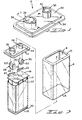
- a 9-volt battery 2 in accordance with the invention comprises a tubular jacket 4 having a rectangular cross-section and having open lower and upper ends 6, 8.
- the upper end of the jacket has an inwardly turned lip or flange, as shown at 10, which retains the upper insulating closure 12 in the jacket.
- the jacket contains a plurality of individual cells 14 which are connected in series with each other and the cells are retained in the jacket by a lower closure 16.
- Insulating spacers 18, 20 are positioned against the upper ends and the lower ends of the cells, and the cells are further held in a compact bundle by a plastic envelope as shown at 22.
- Ribbon-like leads 24, 26 extend from the cells and are connected to terminals 28, 30 which are mounted in the upper closure 12 in a manner described below.
- the upper closure 12 which serves as a connector, is of molded thermoplastic material, such as polypropylene or nylon, and is generally rectangular to conform to the cross-section of the jacket.
- Closure 12 has an upper surface 32 and a lower surface 33, as viewed in the drawing.
- the upper surface is the external surface in the assembled battery and the lower surface 33 is the internal surface.
- the closure is of reduced width around its periphery as shown at 34, so that the central section of the closure will be snugly received in the open upper.end 8 of the jacket.
- Two terminal supporting portions 36, 38 are integral with the closure 12 and extend upwardly from the external surface 32 of the ⁇ closure. These terminal supporting portions support the two terminals 28, 30 in a manner described below. ;
- the terminal support 38 for the terminal 30 is a hollow, slightly conical projection having an internal surface 40 and an external surface 42, which is inclined outwardly from the base of the support.
- Opposed recesses 44 extend inwardly from the surface 32 and partially surround the support 38, the inner ends of these recesses 44 being closed by thin membranes 46 which are produced when the closure is molded.
- the terminal 30 is a generally U-shaped member having a web 48 and arcuate opposed sidewalls 50 which extend upwardly from the web.
- the curvature of the sidewalls conforms to the external surface 42 of the terminal support 38 so that the terminal sidewalls will be against the external surface 42 of the support when the parts are assembled as shown in Figure 6.
- the terminal 30 and the terminal 28 should be of a conductive sheet metal. Good results will be obtained with a low carbon cold rolled steel, such as the steels identified in the Unified Numbering System as G-10080 or G-10100.
- the terminals can be plated with nickel and overplated with tin for enhanced electrical characteristics and corrosion protection.
- the tooling used to assemble the terminal 30 to the closure 12 comprises a lower guide 52 having a cylindrical circular opening in which a lower insertion tool 56 is slideably mounted.
- the guide 52 has a supporting surface 54 on which the closure 12 is supported with the terminal supporting portion 38 concentric with respect to the opening in the guide.
- the closure 12 is clamped against the surface 54 by an upper guide 58 having a lower surface 59 which conforms to the surface 32 of the closure.
- the upper guide 58 has a central opening in which a ram 60 is slideably contained. The lower portions of this opening converge slightly, as shown at 66, so that these portions of the opening are substantially parallel to the diverging surface portions 42 of the support 38.
- the ram 60 has a lower end which has a central projecting portion 62 that is surrounded by a toroidal recess 64.
- the surface of the recess 64 functions as a forming surface in that it forms the upper ends 68 of the sidewalls 50 of the terminal inwardly and over the upper free ends of the support 38.
- the lower inserter 56 is moved inwardly until the upper ends 68 of the sidewalls 50 pierce the membranes 46 and the sidewalls extend along the external surface 42 of the support 38. Thereafter, the ram 60 is moved.downwardly to the position of Figure 6 and the ends 68 of the sidewalls are formed inwardly as shown, so that the terminal is securely fixed to the support. Similar tooling can be used to assemble the socket terminal 28, described below, to the closure 12.
- the membranes 46 are not destroyed when they are pierced by the sidewalls 50 and the edges of the membranes which are formed upon piecing bear against the sidewalls of the terminals and provide a seal which surrounds the sidewalls 50.
- the terminal 30 and support 38 are dimensioned to be received in snap fastener socket terminals which may be secured to the ends of wires.
- the terminals and the support 38 will be sufficiently resilient to cooperate with a socket terminal fastener on a lead wire.
- the socket terminal 28 is similar in many respects to the plug terminal 30 and the parts of the socket terminal shown in Figure 7 are identified with the same reference numerals, differentiated by prime marks, as are used to identify the parts of the plug terminal in Figures 5 and 6. It will be apparent from Figure 7 that the integral support 36 on the closure 12 for the socket terminal is cylindrical rather than conical, and the terminal itself is substantially cylindrical when it is assembled to the support.
- the recesses 44, 44' associated with the terminal support 36 are adjacent to the internal wall 40' of the support 36 so that the sidewalls of the terminal are against the internal surface of the support.
- the sidewalls 50' also have inwardly directed dimples 70 which provide the snap effect of the snap fastener type terminals used for 9-volt battery connectors.
- the terminal 28 is a socket type terminal and is dimensioned to receive a plug terminal.
- Closures 12, terminals 28, and terminals 30 can be manufactured as loose-piece items and the terminals can be assembled to the closure by relatively simple tooling and fixtures, if desired. Under many circumstances, however, it will be desirable to produce the closures as a continuous strip 84, the terminals 30 as a continuous strip 74, and the terminals 28 as a continuous strip 72.
- the closure may be produced in a continuous molding operation with each closure 12 connected to the next adjacent closure of the strip by a connecting section 86.
- the terminals in the strips 72, 74 are also connected to each other by connecting strip sections 76.
- the terminals can be assembled to the closure by means of automatic machinery in accordance with the principles shown in Figure 4.
- a terminal 30 is assembled to each closure in a first assembly station in which the leading terminal of the strip 74 is removed from the strip and assembled to the closure by tooling of the type shown in Figures 5 and 6.
- a terminal 28 is assembled to the closure and the closure is thereafter severed from the adjacent connecting section 86 of the strip 84.
- the leads 24, 26 can then be connected to the internal contact portions 48, 48' of the terminals in a welding station by means of electrodes 78, 80 to produce the welds shown at 82.
- the electrodes 78 can be brought to bear against the surfaces of the webs 48, 48' of the terminals because of the fact that the support members 36, 38 are hollow.
- the continuous strip 84 of closures can also be used to carry the cells of the batteries along a production line beyond the station shown in Figure 2 at which the leads 24, 26 are welded to the internal contact portions of the terminals as shown at 82. If this alternative manufacturing process is employed, the closures are not severed from the strip 84 at the welding station and the strip, with the cell leads 24, 26 welded to the terminals, is fed to subsequent assembly stations at which the jacket 4 would be assembled to the cells, the bottom closures would be assembled to the jackets of the battery, and the ends of the jackets would be formed over the closures. Severing of the closures 12 from the strip 84 would take place during the final stages of the manufacturing process.
- the supported terminals 28, 30 on a battery closure as described above can be coupled to identical terminals on a connector of the type used to connect lead wires to a 9-volt battery.
- the supported terminals 28, 30 can also be coupled to snap fastener terminals of the all-metal type which are at present used as connectors for connecting lead wires to terminals on a 9-volt battery.
- the snap action of the terminals 28, 30 is preferably obtained entirely, or almost entirely, from the terminal supporting portions 36, 38 of the connector of closure 12.
- the terminals 28, 30 can therefore be of relatively thin metal.
- Figure 8 shows a connector 12' which is in many respects similar to the connector or closure 12 described above but which is adapted to be mounted on a circuit board 90.
- the sidewalls 92 of the terminals 28', 30' extend through the circuit board and are soldered to conductors on the underside of the board as shown.
- the plug terminal 30' extends over the upper surface of the support 38' and the web of the terminal, therefore, rests on the upper surface of the support 38'.
- the socket terminal 28' has a double thickness 88 of metal contained in the hollow interior of the support 36'.
- the terminals 28', 30' are in the embodiment of Figure 8 inserted downwardly, as viewed in the drawing, into the surface 32' and beyond the lower surface 33' of the support.
- Figure 9 shows a further embodiment in which the end portions 96 of the sidewalls have wire receiving slots 98 by means of which the terminals can be connected to lead wires.
- the terminals 30" and 28" have been oriented in Figure 9 such that the wire receiving slots 98 are in side-by-side relationship rather than aligned relationship.
- a suitable plastic cover 100 can be provided on the lower surface of the connector shown in Figure 9. This type of connector can then be used to connect lead wires to a 9-volt battery.
- the cover can be retained on the flat molded support by a detent means or an adhesive.
Landscapes
- Chemical & Material Sciences (AREA)
- Chemical Kinetics & Catalysis (AREA)
- Electrochemistry (AREA)
- General Chemical & Material Sciences (AREA)
- Physics & Mathematics (AREA)
- General Physics & Mathematics (AREA)
- Connection Of Batteries Or Terminals (AREA)
Applications Claiming Priority (2)
| Application Number | Priority Date | Filing Date | Title |
|---|---|---|---|
| US289443 | 1981-08-03 | ||
| US06/289,443 US4394059A (en) | 1981-08-03 | 1981-08-03 | Connector of a type used with dry cell batteries and manufacturing method |
Publications (3)
| Publication Number | Publication Date |
|---|---|
| EP0072123A2 true EP0072123A2 (fr) | 1983-02-16 |
| EP0072123A3 EP0072123A3 (en) | 1983-10-05 |
| EP0072123B1 EP0072123B1 (fr) | 1986-12-30 |
Family
ID=23111557
Family Applications (1)
| Application Number | Title | Priority Date | Filing Date |
|---|---|---|---|
| EP82303861A Expired EP0072123B1 (fr) | 1981-08-03 | 1982-07-22 | Connecteur du type utilisé dans des batteries constitués d'éléments secs |
Country Status (5)
| Country | Link |
|---|---|
| US (1) | US4394059A (fr) |
| EP (1) | EP0072123B1 (fr) |
| JP (1) | JPS5828169A (fr) |
| CA (1) | CA1171456A (fr) |
| DE (1) | DE3274928D1 (fr) |
Cited By (3)
| Publication number | Priority date | Publication date | Assignee | Title |
|---|---|---|---|---|
| GB2169130A (en) * | 1984-12-20 | 1986-07-02 | Lucas Ind Plc | Electric storage battery |
| FR2932023A1 (fr) * | 2008-06-02 | 2009-12-04 | Valeo Equip Electr Moteur | Connecteur, notamment pour dispositif de stockage d'energie |
| EP3474342A1 (fr) * | 2017-10-17 | 2019-04-24 | Contemporary Amperex Technology Co., Limited | Ensemble capuchon de batterie et batterie secondaire |
Families Citing this family (30)
| Publication number | Priority date | Publication date | Assignee | Title |
|---|---|---|---|---|
| US4666799A (en) * | 1983-09-19 | 1987-05-19 | Medtronic, Inc. | Current collectors for batteries having cathode-electrolytes and batteries incorporating same |
| US4513068A (en) * | 1983-10-20 | 1985-04-23 | Motorola, Inc. | Auxiliary battery charging terminal |
| US4640874A (en) * | 1985-07-29 | 1987-02-03 | Duracell Inc. | Metal/air cell |
| ZA949398B (en) * | 1993-12-23 | 1995-08-08 | Motorola Inc | Dual beam contact |
| US5509813A (en) * | 1994-05-20 | 1996-04-23 | Lu; Sheng N. | Joint assembly for electrically engaging a portable computer with a battery |
| US5664973A (en) * | 1995-01-05 | 1997-09-09 | Motorola, Inc. | Conductive contact |
| JP3707595B2 (ja) * | 1998-09-09 | 2005-10-19 | 矢崎総業株式会社 | バッテリ接続プレート |
| US6319631B1 (en) * | 1999-09-08 | 2001-11-20 | Motorola, Inc. | Contact system for interconnection of substrate and battery cell |
| US6613473B1 (en) * | 2000-09-11 | 2003-09-02 | Leon Tong | Battery with cylindrical cells |
| US6586134B2 (en) | 2001-03-29 | 2003-07-01 | Wilson Greatbatch Ltd. | Electrode lead to case and header, laser/electron beam welding |
| US6701998B2 (en) | 2002-03-29 | 2004-03-09 | Water Gremlin Company | Multiple casting apparatus and method |
| TWI255085B (en) * | 2002-04-02 | 2006-05-11 | Delta Electronics Inc | Assembly structure of adapter |
| US8701743B2 (en) | 2004-01-02 | 2014-04-22 | Water Gremlin Company | Battery parts and associated systems and methods |
| US7229327B2 (en) * | 2005-05-25 | 2007-06-12 | Alcoa Fujikura Limited | Canted coil spring power terminal and sequence connection system |
| WO2008049112A2 (fr) * | 2006-10-19 | 2008-04-24 | Amphenol Corporation | Système de connecteur pour connecter des câbles à une batterie |
| CN101369649B (zh) * | 2008-09-30 | 2010-06-02 | 赛恩斯能源科技有限公司 | 电池连接装置 |
| WO2010127289A1 (fr) | 2009-04-30 | 2010-11-04 | Water Gremlin Company | Parties de batterie ayant des caractéristiques de retenue et d'étanchéité et procédés associés de fabrication et d'utilisation |
| US7857658B1 (en) * | 2009-10-26 | 2010-12-28 | Microsoft Corporation | Multiple orientation battery connector |
| JP5218565B2 (ja) * | 2010-01-13 | 2013-06-26 | トヨタ自動車株式会社 | 電池の製造方法 |
| US20110174459A1 (en) * | 2010-01-19 | 2011-07-21 | Water Gremlin Company | Mold assemblies including removable inserts and associated methods of use and manufacture |
| US20110262806A1 (en) * | 2010-03-12 | 2011-10-27 | Water Gremlin Company | Battery parts having retaining and sealing features, and associated methods of manufacture and use |
| US20110250493A1 (en) * | 2010-03-12 | 2011-10-13 | Water Gremlin Company | Battery parts and associated methods of manufacture and use |
| US8691423B2 (en) | 2011-03-14 | 2014-04-08 | Joseph Krzywicki | Rebuilt rechargeable battery with welded grip |
| US9748551B2 (en) | 2011-06-29 | 2017-08-29 | Water Gremlin Company | Battery parts having retaining and sealing features and associated methods of manufacture and use |
| TWI470876B (zh) * | 2012-04-25 | 2015-01-21 | Wistron Corp | 電連接總成、電池裝置及電子裝置 |
| US9954214B2 (en) | 2013-03-15 | 2018-04-24 | Water Gremlin Company | Systems and methods for manufacturing battery parts |
| USD866558S1 (en) * | 2016-11-11 | 2019-11-12 | Samsung Electronics Co., Ltd. | SSD storage device |
| US10300545B2 (en) * | 2017-10-12 | 2019-05-28 | Snap Inc. | Low-profile mechanical retention |
| MX2021006454A (es) | 2018-12-07 | 2021-07-02 | Water Gremlin Co | Partes de bateria que tienen barreras contra acidos sin solventes y sistemas y metodos asociados. |
| DE102019129805B3 (de) * | 2019-11-05 | 2021-05-06 | Auto-Kabel Management Gmbh | Modulverbinder |
Citations (2)
| Publication number | Priority date | Publication date | Assignee | Title |
|---|---|---|---|---|
| GB1203775A (en) * | 1966-11-09 | 1970-09-03 | Dunkel Otto Gmbh | Improvements relating to electric plug and socket contacts |
| US4179545A (en) * | 1978-05-25 | 1979-12-18 | P. R. Mallory & Co. Inc. | Battery with protectively jacketed female terminal |
Family Cites Families (6)
| Publication number | Priority date | Publication date | Assignee | Title |
|---|---|---|---|---|
| US1368817A (en) * | 1913-07-05 | 1921-02-15 | Paul M Marko | Storage battery |
| US1983037A (en) * | 1933-10-23 | 1934-12-04 | Dietograph Products Company In | Dry battery packet |
| US2225460A (en) * | 1936-02-04 | 1940-12-17 | Burgess Battery Co | Battery |
| NL135703C (fr) * | 1959-10-30 | |||
| US4087595A (en) * | 1973-04-23 | 1978-05-02 | P.R. Mallory & Co. Inc. | Multi-cell battery and method of making |
| US4226497A (en) * | 1979-01-08 | 1980-10-07 | General Electric Company | Battery terminal harness having improved fastening means for preventing application of reverse polarity voltage |
-
1981
- 1981-08-03 US US06/289,443 patent/US4394059A/en not_active Expired - Lifetime
-
1982
- 1982-06-23 CA CA000405863A patent/CA1171456A/fr not_active Expired
- 1982-07-22 DE DE8282303861T patent/DE3274928D1/de not_active Expired
- 1982-07-22 EP EP82303861A patent/EP0072123B1/fr not_active Expired
- 1982-08-02 JP JP57135057A patent/JPS5828169A/ja active Pending
Patent Citations (2)
| Publication number | Priority date | Publication date | Assignee | Title |
|---|---|---|---|---|
| GB1203775A (en) * | 1966-11-09 | 1970-09-03 | Dunkel Otto Gmbh | Improvements relating to electric plug and socket contacts |
| US4179545A (en) * | 1978-05-25 | 1979-12-18 | P. R. Mallory & Co. Inc. | Battery with protectively jacketed female terminal |
Cited By (5)
| Publication number | Priority date | Publication date | Assignee | Title |
|---|---|---|---|---|
| GB2169130A (en) * | 1984-12-20 | 1986-07-02 | Lucas Ind Plc | Electric storage battery |
| US4693948A (en) * | 1984-12-20 | 1987-09-15 | Lucas Industries Public Limited Company | Electric storage battery |
| FR2932023A1 (fr) * | 2008-06-02 | 2009-12-04 | Valeo Equip Electr Moteur | Connecteur, notamment pour dispositif de stockage d'energie |
| EP3474342A1 (fr) * | 2017-10-17 | 2019-04-24 | Contemporary Amperex Technology Co., Limited | Ensemble capuchon de batterie et batterie secondaire |
| US11482748B2 (en) | 2017-10-17 | 2022-10-25 | Contemporary Amperex Technology Co., Limited | Battery cap assembly and secondary battery |
Also Published As
| Publication number | Publication date |
|---|---|
| EP0072123A3 (en) | 1983-10-05 |
| JPS5828169A (ja) | 1983-02-19 |
| CA1171456A (fr) | 1984-07-24 |
| DE3274928D1 (en) | 1987-02-05 |
| US4394059A (en) | 1983-07-19 |
| EP0072123B1 (fr) | 1986-12-30 |
Similar Documents
| Publication | Publication Date | Title |
|---|---|---|
| EP0072123B1 (fr) | Connecteur du type utilisé dans des batteries constitués d'éléments secs | |
| US4099320A (en) | Method of making a miniature plug-in fuse | |
| US4040702A (en) | Solderless termination system | |
| JPS6013268B2 (ja) | 電気コネクタ | |
| EP1139462A2 (fr) | Batterie modulaire et méthode de fabrication | |
| GB1497629A (en) | Electrical terminal and modular electrical connector assembly | |
| US4790769A (en) | Telephone modular jack | |
| US4315664A (en) | Modular jack | |
| IE850434L (en) | Contact for chip carriers and method of inserting same into¹a housing | |
| US4596440A (en) | Electrical probe contact | |
| EP0029836B1 (fr) | Interconnecteurs electriques | |
| US4327958A (en) | Connector jack | |
| US4373769A (en) | Electrical connector including insulation-opening contact | |
| GB2075772A (en) | Electrical contact elements on a carrier strip | |
| US4127935A (en) | Method for assembly of electrical connectors | |
| CA1099356A (fr) | Connecteur a glissiere d'accouplement rapide | |
| US2983778A (en) | Battery clip | |
| US4575176A (en) | Manufacture of pin headers | |
| US2811705A (en) | Electrical connector | |
| US4243286A (en) | Insulation displacement connector | |
| CA1195398A (fr) | Borne de raccordement sans soudure | |
| US5421743A (en) | Safety battery snap | |
| US5786108A (en) | Electrochemical cell | |
| EP0171193A2 (fr) | Terminal double en tôle métallique pénétrant dans l'isolation | |
| US20030220010A1 (en) | Electrical connector and method of connecting lead lines therefor |
Legal Events
| Date | Code | Title | Description |
|---|---|---|---|
| PUAI | Public reference made under article 153(3) epc to a published international application that has entered the european phase |
Free format text: ORIGINAL CODE: 0009012 |
|
| AK | Designated contracting states |
Designated state(s): BE DE FR GB IT NL |
|
| PUAL | Search report despatched |
Free format text: ORIGINAL CODE: 0009013 |
|
| AK | Designated contracting states |
Designated state(s): BE DE FR GB IT NL |
|
| 17P | Request for examination filed |
Effective date: 19840313 |
|
| ITF | It: translation for a ep patent filed |
Owner name: GUZZI E RAVIZZA S.R.L. |
|
| GRAA | (expected) grant |
Free format text: ORIGINAL CODE: 0009210 |
|
| AK | Designated contracting states |
Kind code of ref document: B1 Designated state(s): BE DE FR GB IT NL |
|
| REF | Corresponds to: |
Ref document number: 3274928 Country of ref document: DE Date of ref document: 19870205 |
|
| ET | Fr: translation filed | ||
| PLBE | No opposition filed within time limit |
Free format text: ORIGINAL CODE: 0009261 |
|
| STAA | Information on the status of an ep patent application or granted ep patent |
Free format text: STATUS: NO OPPOSITION FILED WITHIN TIME LIMIT |
|
| 26N | No opposition filed | ||
| PGFP | Annual fee paid to national office [announced via postgrant information from national office to epo] |
Ref country code: DE Payment date: 19920609 Year of fee payment: 11 |
|
| PGFP | Annual fee paid to national office [announced via postgrant information from national office to epo] |
Ref country code: FR Payment date: 19920610 Year of fee payment: 11 |
|
| PGFP | Annual fee paid to national office [announced via postgrant information from national office to epo] |
Ref country code: GB Payment date: 19920617 Year of fee payment: 11 |
|
| PGFP | Annual fee paid to national office [announced via postgrant information from national office to epo] |
Ref country code: BE Payment date: 19920623 Year of fee payment: 11 |
|
| ITTA | It: last paid annual fee | ||
| PGFP | Annual fee paid to national office [announced via postgrant information from national office to epo] |
Ref country code: NL Payment date: 19920731 Year of fee payment: 11 |
|
| PG25 | Lapsed in a contracting state [announced via postgrant information from national office to epo] |
Ref country code: GB Effective date: 19930722 |
|
| PG25 | Lapsed in a contracting state [announced via postgrant information from national office to epo] |
Ref country code: BE Effective date: 19930731 |
|
| BERE | Be: lapsed |
Owner name: AMP INC. (UNE SOC. DE PENNSYLVANIE) Effective date: 19930731 |
|
| PG25 | Lapsed in a contracting state [announced via postgrant information from national office to epo] |
Ref country code: NL Effective date: 19940201 |
|
| NLV4 | Nl: lapsed or anulled due to non-payment of the annual fee | ||
| GBPC | Gb: european patent ceased through non-payment of renewal fee |
Effective date: 19930722 |
|
| PG25 | Lapsed in a contracting state [announced via postgrant information from national office to epo] |
Ref country code: FR Effective date: 19940331 |
|
| PG25 | Lapsed in a contracting state [announced via postgrant information from national office to epo] |
Ref country code: DE Effective date: 19940401 |
|
| REG | Reference to a national code |
Ref country code: FR Ref legal event code: ST |