EP0071998B1 - Coronaentladungsapparat für eine elektrostatische photographische Kopiermaschine - Google Patents
Coronaentladungsapparat für eine elektrostatische photographische Kopiermaschine Download PDFInfo
- Publication number
- EP0071998B1 EP0071998B1 EP82107138A EP82107138A EP0071998B1 EP 0071998 B1 EP0071998 B1 EP 0071998B1 EP 82107138 A EP82107138 A EP 82107138A EP 82107138 A EP82107138 A EP 82107138A EP 0071998 B1 EP0071998 B1 EP 0071998B1
- Authority
- EP
- European Patent Office
- Prior art keywords
- corona discharging
- discharging apparatus
- shield case
- shield
- corona
- Prior art date
- Legal status (The legal status is an assumption and is not a legal conclusion. Google has not performed a legal analysis and makes no representation as to the accuracy of the status listed.)
- Expired
Links
- 238000007599 discharging Methods 0.000 title claims description 46
- 230000001105 regulatory effect Effects 0.000 claims description 11
- 239000011810 insulating material Substances 0.000 claims description 3
- 230000000694 effects Effects 0.000 description 4
- 238000004519 manufacturing process Methods 0.000 description 4
- 239000002245 particle Substances 0.000 description 4
- 238000004140 cleaning Methods 0.000 description 3
- 238000010276 construction Methods 0.000 description 3
- 230000007246 mechanism Effects 0.000 description 3
- 230000002159 abnormal effect Effects 0.000 description 2
- 230000009467 reduction Effects 0.000 description 2
- 238000000926 separation method Methods 0.000 description 2
- 239000004698 Polyethylene Substances 0.000 description 1
- 230000008901 benefit Effects 0.000 description 1
- 230000003247 decreasing effect Effects 0.000 description 1
- 230000007547 defect Effects 0.000 description 1
- 230000005611 electricity Effects 0.000 description 1
- 230000006872 improvement Effects 0.000 description 1
- 239000004417 polycarbonate Substances 0.000 description 1
- 229920000515 polycarbonate Polymers 0.000 description 1
- -1 polyethylene Polymers 0.000 description 1
- 229920000573 polyethylene Polymers 0.000 description 1
- 230000008439 repair process Effects 0.000 description 1
- 238000010186 staining Methods 0.000 description 1
- 239000000126 substance Substances 0.000 description 1
Images


Classifications
-
- G—PHYSICS
- G03—PHOTOGRAPHY; CINEMATOGRAPHY; ANALOGOUS TECHNIQUES USING WAVES OTHER THAN OPTICAL WAVES; ELECTROGRAPHY; HOLOGRAPHY
- G03G—ELECTROGRAPHY; ELECTROPHOTOGRAPHY; MAGNETOGRAPHY
- G03G15/00—Apparatus for electrographic processes using a charge pattern
- G03G15/02—Apparatus for electrographic processes using a charge pattern for laying down a uniform charge, e.g. for sensitising; Corona discharge devices
- G03G15/0275—Arrangements for controlling the area of the photoconductor to be charged
-
- G—PHYSICS
- G03—PHOTOGRAPHY; CINEMATOGRAPHY; ANALOGOUS TECHNIQUES USING WAVES OTHER THAN OPTICAL WAVES; ELECTROGRAPHY; HOLOGRAPHY
- G03G—ELECTROGRAPHY; ELECTROPHOTOGRAPHY; MAGNETOGRAPHY
- G03G15/00—Apparatus for electrographic processes using a charge pattern
- G03G15/02—Apparatus for electrographic processes using a charge pattern for laying down a uniform charge, e.g. for sensitising; Corona discharge devices
- G03G15/0291—Apparatus for electrographic processes using a charge pattern for laying down a uniform charge, e.g. for sensitising; Corona discharge devices corona discharge devices, e.g. wires, pointed electrodes, means for cleaning the corona discharge device
Definitions
- the present invention relates to an improvement of a corona discharging apparatus used in an electrifying apparatus or a transfer device or the cleaning device of an electrostatic photographic copying machine.
- the width of the opening is less than the width of the opening of corona discharge for a transfer section in a conventional copying equipment.
- the setting of said length is usually done at the stage of design and manufacture and must be done very strictly.
- the design and manufacture of the length of thin wire must be controlled and adjusted again. This causes much trouble and is very unfavourable also in respect of cost.
- a corona discharging apparatus used in an electrostatic photographic copying machine comprising a shield case provided with an open portion opposite to the circumferential surface of a sensitive drum and mounted on the fixed wall of said electrostatic photographic copying machine substantially in parallel to said sensitive drum in the longitudinal direction thereof, at least one thin corona discharging wire longitudinally arranged in said shield case and comprising according to the present invention a shield cover for regulating the electrically effective width of said thin wire, said shield cover being detachably and dislocatably mounted on the longitudinal end of said open portion of said shield case.
- the length of said thin wire for discharging corona can be easily regulated after assembling and an individual corona discharging apparatus can be achieved by adjusting the electrically active width to strictly correspond with the performance needed.
- the spatter of the toner owing to an unsuitable length of the wire as with some conventional apparatus can be prevented, and thereby staining due to the toner spattering, the gradual reduction of the electric discharge effect, the development of abnormal electric discharge and the like can be avoided.
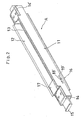
- the electrostatic photographic copying machine schematically depicted in Fig. 1 for which a corona discharging apparatus according to the present invention can be advantageously used comprises an electrifying apparatus 3, an exposure device 4, a developing station 5, a transfer device 6, a cleaning apparatus 7 all of which are arranged along the outer circumferential surface of a rotary sensitive drum 2 and paper transfer rollers R for transferring copying papers from a paper-supplying apparatus 8, 9 to a fixing station 1 and a paper-discharging device 10 through said transfer device 6.
- Said electrifying apparatus 3 said transfer device 6 and said cleaning apparatus 7 each comprises a corona discharging apparatus A, B and C, respectively which are mounted (not shown in Fig. 1) on the fixed inside wall of the electrostatic photographic copying machine.
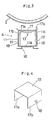
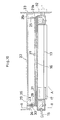
- FIGs. 2 and 3 designates a shield case provided with an open portion 12 opened toward said sensitive drum 2 and a thin wire 13 for discharging corona therein, 14,14' designate a pair of bases for stretching said thin wire 13; 15 refers to a handle integrally formed so as to project toward one side from one (e.g.
- the left side plate 17a and the right side plate 17b of said shield cover 17 are provided with projections 18 and 18', respectively, projecting outwardly, said shield cover 17 being detachably and dislocatably mounted on one longitudinal end of said open portion 12 of said shield case 11, said projections 18,18' extending in any one of a plurality of holes 19, 19' formed on the left side wall 11 b and the right side wall 11c of said shield case 11, as shown in Fig. 2.
- the electrically active width of said thin wire 13 can be regulated according to the specific demands and circumstances by means of said shield cover 17.
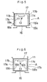
- said shield case 11 is provided with projections 18a, 18'a, 18b, 18'b, on the outside or the inside of said left side wall 11 b and said right side wall 11c thereof, and said shield cover 17 formed in the shape of nearly an upside down U in the longitudinal direction thereof is provided with a plurality of holes 19a, 19'a and 19b, 19'b, respectively on the side walls 17a, 17b thereof for detachably mounting of said shield cover 17 on one longitudinal end of said open portion 12 of said shield case 11.
- a shield cover 17 is shaped in the form of a flat plate. Projections 18c, 18'c formed on both sides of said shield cover 17 are engaged with a plurality of holes 19c, 19'c formed in the longitudinal direction at the upper part of the left side wall 11b and the right side wall 11c of said shield case 11 similarly to the above described other preferred embodiment of the present invention.
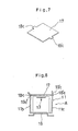
- a shield cover 17 shaped in the form of a flat plate is provided with a pair of long holes 20, 20' (a plurality of round holes may be used instead), said shield cover 27 being detachably and dislocatably mounted on the longitudinal end of the open portion 12 of the shield case 11 screwing a screw 21 made of insulating material such as polyethylene and the like to through said long holes 20, 20' and into tapped holes (not shown) of a base 14.
- reference numeral 22 designates a fixed inside wall of an electrostatic photographic copying machine, said wall 22 being provided with a supporting bracket 24 having a long hole 23 at one longitudinal end along the rotary axis of said sensitive drum 2 and a channel member 26 having a bracket 25 fixedly mounted at another end thereof. Said channel member 26 is provided with a rail-receiving member 27 on the open portion opposite to said sensitive drum 2.
- Said rail-receiving member 27 is provided with a bracket 29 having a tapped hole 28 corresponding to said supporting bracket 24 at one end thereof and fixedly mounted on said supporting bracket 24 by means of a screw 30 passing through said long hole 23 and said tapped hole 28, another end 27a of said rail-receiving member 27 being inserted in a hole 25a formed in said bracket 25 to be supported.
- said rail-receiving member 27 can be detached in the radial direction of said sensitive drum 2 with said hole 25a of said bracket 25 as a supporting point and can be fixed at an optional position within the allowable range of said long hole 23.
- said corona discharging apparatus A is provided with a rail member 16 corresponding to said rail-receiving member 27 and mounted on said fixed wall 22 through said rail member 16, said rail-receiving member 27, said channel member 26 and the like.
- said corona discharging apparatus A is longitudinally slidable and dislocatable relatively to the circumferential surface of said sensitive drum 2 by changing the relative relationship between the positions of said both brackets 24, 29 by means of said screw 30.
- 31 designates a plate spring arranged between said rail member 16 and said rail receiving member 27, both of said rail member 16 and said rail-receiving member 27 being energized by means of said plate spring 31 so that they may be always engaged with each other fixedly.
- 15 designates a handle member for longitudinal sliding said corona discharging apparatus A to pull it out or push it in as described above.
- 32 designates a power- supplying connector for said corona discharging apparatus A fixedly mounted on a wall 33 inside the copying machine.
- Said another end of said rail-receiving member 27 may be pivoted swingably on said channel member 26 through a pin and the like instead of fixedly mounting on said channel member 26 by means of said bracket 25. Further, said another end of said rail-receiving member 27 may be dislocatably mounted so as to be moved in the radial direction of said sensitive drum 2 in the same manner as said one end of said rail-receiving member 27.
- FIG. 13 showing a further different preferred embodiment of the present invention in which the dislocating mechanism as shown in Fig. 12 is modified.
- Reference numeral 34 designates a flange mounted on said channel member 26, and 35 refers to a flange mounted on said rail-receiving member 27.
- the position of said rail-receiving member 27 and thereby the position of said corona discharging apparatus A can be regulated by connecting said flange 34 with said flange 35 through a spring 36 by means of a bolt 37 and a nut 38.
- a shield case 11 is mounted on a fixed wall inside a copying machine so that it can be longitudinally dislocated but can not be moved in the radial direction of the sensitive drum.
- a thin corona discharge wire 13 must be provided with a pressing member at one end thereof inside said shield case 11 in order to prevent an uneven exposure in the longitudinal direction of said sensitive drum 2. Accordingly, it is inevitable to adopt a structure in which the distance between one end of said thin wire 13 and said sensitive drum 2 is changed by regulating said pressing member. This structure leads to delicate and complicated construction problems, and the regulating operation for preventing an uneven exposure is remarkably difficult.
- the shield case 11 of the corona discharging apparatus A is mounted on said fixed wall at at least one of its longitudinal ends so that it can be dislocatable relative to said sensitive drum 2 instead of the positional regulation of the thin corona discharge wire 13 itself relative to the circumferential surface of said sensitive drum 2.
- the position of said shield case 11, that is to say said corona discharging apparatus A as a whole can be regulated relatively to the circumferential surface of said sensitive drum 2.
- the operating mechanism for regulating the position of said shield case 11 can be simplified in construction and easily operated contrary to the conventional apparatus since it is not necessary to place said operating mechanism for regulating the position of said shield case 11 in a narrow space inside said shield case 11. That is to say, the operation for preventing an uneven exposure can be easily achieved even though the construction is simple as a whole.
Landscapes
- Physics & Mathematics (AREA)
- Engineering & Computer Science (AREA)
- Plasma & Fusion (AREA)
- General Physics & Mathematics (AREA)
- Electrostatic Charge, Transfer And Separation In Electrography (AREA)
Claims (5)
Applications Claiming Priority (4)
| Application Number | Priority Date | Filing Date | Title |
|---|---|---|---|
| JP11848481U JPS5823339U (ja) | 1981-08-08 | 1981-08-08 | 静電写真複写機におけるコロナ放電装置 |
| JP11848581U JPS5823340U (ja) | 1981-08-08 | 1981-08-08 | 静電写真複写機におけるコロナ放電装置取付構造 |
| JP118485/81 | 1981-08-08 | ||
| JP118484/81 | 1981-08-08 |
Publications (3)
| Publication Number | Publication Date |
|---|---|
| EP0071998A2 EP0071998A2 (de) | 1983-02-16 |
| EP0071998A3 EP0071998A3 (en) | 1983-07-20 |
| EP0071998B1 true EP0071998B1 (de) | 1985-11-13 |
Family
ID=26456415
Family Applications (1)
| Application Number | Title | Priority Date | Filing Date |
|---|---|---|---|
| EP82107138A Expired EP0071998B1 (de) | 1981-08-08 | 1982-08-06 | Coronaentladungsapparat für eine elektrostatische photographische Kopiermaschine |
Country Status (3)
| Country | Link |
|---|---|
| US (1) | US4469428A (de) |
| EP (1) | EP0071998B1 (de) |
| DE (1) | DE3267433D1 (de) |
Families Citing this family (8)
| Publication number | Priority date | Publication date | Assignee | Title |
|---|---|---|---|---|
| US4575329A (en) * | 1984-01-09 | 1986-03-11 | Andreas Ahlbrandt | Electrode element for corona treater |
| US5017964A (en) * | 1989-11-29 | 1991-05-21 | Am International, Inc. | Corona charge system and apparatus for electrophotographic printing press |
| JPH0511160U (ja) * | 1991-07-25 | 1993-02-12 | 旭光学工業株式会社 | コロナチヤージヤのグリツト位置決め構造 |
| DE4305686C2 (de) * | 1992-02-24 | 1999-07-15 | Fujitsu Ltd | Tonerbild-Übertragungsvorrichtung einschließlich einer Übertragungsladevorrichtung und einer Wechselspannungs-Ladungslöschvorrichtung |
| US7315719B2 (en) * | 2005-05-31 | 2008-01-01 | Xerox Corporation | Transfer charge device cover in non-image receiving medium area |
| US20060280531A1 (en) * | 2005-06-10 | 2006-12-14 | Xerox Corporation | Transfer-detack assembly for a xerographic printer |
| US7787812B2 (en) * | 2006-03-17 | 2010-08-31 | Xerox Corporation | Transfer Di-chorotron (Dicor) cover with constant paper current density |
| JP7263172B2 (ja) * | 2019-07-25 | 2023-04-24 | 信越化学工業株式会社 | 多結晶シリコン製造装置 |
Family Cites Families (13)
| Publication number | Priority date | Publication date | Assignee | Title |
|---|---|---|---|---|
| US3374348A (en) * | 1966-05-09 | 1968-03-19 | Scm Corp | Corona unit with a tapered passageway of flectrically nonconductive material betweenconductive housings thatare electrically interconnected |
| DE1522657C3 (de) * | 1966-12-27 | 1973-09-20 | Lumoprint Zindler Kg, 2000 Hamburg | Aufladevorrichtung fur ein elektro statisches Kopiergerat |
| US3578970A (en) * | 1968-05-03 | 1971-05-18 | Plastic Coating Corp | Variable width corona discharge apparatus with means to shield or vary a predetermined length of a corona discharge wire |
| US3609354A (en) * | 1969-06-18 | 1971-09-28 | David L Herman | Corona assembly for electrostatic copy machines |
| US4089600A (en) * | 1970-03-11 | 1978-05-16 | Canon Kabushiki Kaisha | Corona discharge device for electrophotographic copying machine |
| US3764804A (en) * | 1972-01-24 | 1973-10-09 | Pitney Bowes Inc | Operator serviceable corona charging apparatus |
| GB1454409A (en) * | 1973-12-21 | 1976-11-03 | Xerox Corp | Corona generating devices |
| US4174170A (en) * | 1976-12-16 | 1979-11-13 | Minolta Camera Kabushiki Kaisha | Conductive toner transfer photocopying machine |
| US4099219A (en) * | 1976-12-17 | 1978-07-04 | Xerox Corporation | Coronode tensioning and support arrangement |
| US4110811A (en) * | 1977-05-31 | 1978-08-29 | Xerox Corporation | Support structure for a corona generating device |
| DE2849233C2 (de) * | 1978-11-13 | 1982-12-09 | Olympia Werke Ag, 2940 Wilhelmshaven | Elektrofotografisches Kopiergerät mit einer Übertragungseinrichtung zur Übertragung eines Tonerbildes auf ein Bildempfangsmaterial |
| US4252431A (en) * | 1979-10-01 | 1981-02-24 | Nashua Corporation | Adjustable corona support |
| US4320957A (en) * | 1980-05-30 | 1982-03-23 | International Business Machines Corp. | Corona wire adjuster |
-
1982
- 1982-07-27 US US06/402,329 patent/US4469428A/en not_active Expired - Fee Related
- 1982-08-06 DE DE8282107138T patent/DE3267433D1/de not_active Expired
- 1982-08-06 EP EP82107138A patent/EP0071998B1/de not_active Expired
Also Published As
| Publication number | Publication date |
|---|---|
| EP0071998A3 (en) | 1983-07-20 |
| US4469428A (en) | 1984-09-04 |
| DE3267433D1 (en) | 1985-12-19 |
| EP0071998A2 (de) | 1983-02-16 |
Similar Documents
| Publication | Publication Date | Title |
|---|---|---|
| EP0071998B1 (de) | Coronaentladungsapparat für eine elektrostatische photographische Kopiermaschine | |
| US4320957A (en) | Corona wire adjuster | |
| US4757342A (en) | Photoreceptor cartridge unit | |
| JPS6360910B2 (de) | ||
| JPH03116066A (ja) | コロナ放電装置 | |
| US4260240A (en) | Movable support for electrostatic corona discharge device | |
| EP0579176A2 (de) | Xerografisches Druck- und Blattverarbeitungsgerät | |
| EP0606138B1 (de) | Spannbefestigungssystem für eine Vorrichtung zur Erzeugung von Coronaentladung | |
| US4876578A (en) | Paper separation charger for use in electrophotographic copier and the like | |
| KR100385379B1 (ko) | 다수의접촉충전부재를이용한카트리지 | |
| US5333036A (en) | Mounting mechanism of process cartridge for image forming apparatus | |
| US5546171A (en) | Displaceable transfer apparatus having a post-transfer guide | |
| EP0911705A1 (de) | Bilderzeugungsgerät | |
| US4974032A (en) | Paper separation charger for use in electrophotographic copier and the like | |
| JPH0435904Y2 (de) | ||
| US5268715A (en) | Photoconductive drum exposure prevention structure in a clamshell-type image forming apparatus | |
| US20050214026A1 (en) | Electrophotographic reproduction system with a multifaceted charging mechanism | |
| US4357092A (en) | Image recording apparatus | |
| JPH0710316A (ja) | 画像形成装置 | |
| JPH0830922B2 (ja) | 画像形成装置の転写前ガイド装置 | |
| US4437001A (en) | Corona generating apparatus | |
| JPH04362313A (ja) | 軸受装置 | |
| JP2935933B2 (ja) | 帯電体構造 | |
| JP2517197Y2 (ja) | 転写装置 | |
| JP3067442B2 (ja) | 画像形成装置 |
Legal Events
| Date | Code | Title | Description |
|---|---|---|---|
| PUAI | Public reference made under article 153(3) epc to a published international application that has entered the european phase |
Free format text: ORIGINAL CODE: 0009012 |
|
| AK | Designated contracting states |
Designated state(s): DE FR GB NL |
|
| PUAL | Search report despatched |
Free format text: ORIGINAL CODE: 0009013 |
|
| AK | Designated contracting states |
Designated state(s): DE FR GB NL |
|
| 17P | Request for examination filed |
Effective date: 19831028 |
|
| GRAA | (expected) grant |
Free format text: ORIGINAL CODE: 0009210 |
|
| AK | Designated contracting states |
Designated state(s): DE FR GB NL |
|
| REF | Corresponds to: |
Ref document number: 3267433 Country of ref document: DE Date of ref document: 19851219 |
|
| ET | Fr: translation filed | ||
| PLBE | No opposition filed within time limit |
Free format text: ORIGINAL CODE: 0009261 |
|
| STAA | Information on the status of an ep patent application or granted ep patent |
Free format text: STATUS: NO OPPOSITION FILED WITHIN TIME LIMIT |
|
| 26N | No opposition filed | ||
| PGFP | Annual fee paid to national office [announced via postgrant information from national office to epo] |
Ref country code: GB Payment date: 19940727 Year of fee payment: 13 |
|
| PGFP | Annual fee paid to national office [announced via postgrant information from national office to epo] |
Ref country code: FR Payment date: 19940809 Year of fee payment: 13 |
|
| PGFP | Annual fee paid to national office [announced via postgrant information from national office to epo] |
Ref country code: DE Payment date: 19940816 Year of fee payment: 13 |
|
| PGFP | Annual fee paid to national office [announced via postgrant information from national office to epo] |
Ref country code: NL Payment date: 19940831 Year of fee payment: 13 |
|
| PG25 | Lapsed in a contracting state [announced via postgrant information from national office to epo] |
Ref country code: GB Effective date: 19950806 |
|
| PG25 | Lapsed in a contracting state [announced via postgrant information from national office to epo] |
Ref country code: NL Effective date: 19960301 |
|
| GBPC | Gb: european patent ceased through non-payment of renewal fee |
Effective date: 19950806 |
|
| PG25 | Lapsed in a contracting state [announced via postgrant information from national office to epo] |
Ref country code: FR Effective date: 19960430 |
|
| NLV4 | Nl: lapsed or anulled due to non-payment of the annual fee |
Effective date: 19960301 |
|
| PG25 | Lapsed in a contracting state [announced via postgrant information from national office to epo] |
Ref country code: DE Effective date: 19960501 |
|
| REG | Reference to a national code |
Ref country code: FR Ref legal event code: ST |