EP0071949A2 - Einlassvorrichtung für eine Brennkraftmaschine - Google Patents
Einlassvorrichtung für eine Brennkraftmaschine Download PDFInfo
- Publication number
- EP0071949A2 EP0071949A2 EP82106983A EP82106983A EP0071949A2 EP 0071949 A2 EP0071949 A2 EP 0071949A2 EP 82106983 A EP82106983 A EP 82106983A EP 82106983 A EP82106983 A EP 82106983A EP 0071949 A2 EP0071949 A2 EP 0071949A2
- Authority
- EP
- European Patent Office
- Prior art keywords
- wall
- intake device
- valve
- passage
- intake port
- Prior art date
- Legal status (The legal status is an assumption and is not a legal conclusion. Google has not performed a legal analysis and makes no representation as to the accuracy of the status listed.)
- Granted
Links
- 238000002485 combustion reaction Methods 0.000 title claims description 10
- 238000013459 approach Methods 0.000 claims description 2
- 239000012530 fluid Substances 0.000 claims 2
- 238000011144 upstream manufacturing Methods 0.000 claims 1
- 239000000203 mixture Substances 0.000 description 17
- 230000006835 compression Effects 0.000 description 6
- 238000007906 compression Methods 0.000 description 6
- 238000010276 construction Methods 0.000 description 2
- 238000004891 communication Methods 0.000 description 1
- 150000001875 compounds Chemical class 0.000 description 1
- 238000003780 insertion Methods 0.000 description 1
- 230000037431 insertion Effects 0.000 description 1
- 238000012986 modification Methods 0.000 description 1
- 230000004048 modification Effects 0.000 description 1
Images


Classifications
-
- F—MECHANICAL ENGINEERING; LIGHTING; HEATING; WEAPONS; BLASTING
- F02—COMBUSTION ENGINES; HOT-GAS OR COMBUSTION-PRODUCT ENGINE PLANTS
- F02M—SUPPLYING COMBUSTION ENGINES IN GENERAL WITH COMBUSTIBLE MIXTURES OR CONSTITUENTS THEREOF
- F02M35/00—Combustion-air cleaners, air intakes, intake silencers, or induction systems specially adapted for, or arranged on, internal-combustion engines
- F02M35/10—Air intakes; Induction systems
- F02M35/10209—Fluid connections to the air intake system; their arrangement of pipes, valves or the like
- F02M35/10229—Fluid connections to the air intake system; their arrangement of pipes, valves or the like the intake system acting as a vacuum or overpressure source for auxiliary devices, e.g. brake systems; Vacuum chambers
-
- F—MECHANICAL ENGINEERING; LIGHTING; HEATING; WEAPONS; BLASTING
- F02—COMBUSTION ENGINES; HOT-GAS OR COMBUSTION-PRODUCT ENGINE PLANTS
- F02B—INTERNAL-COMBUSTION PISTON ENGINES; COMBUSTION ENGINES IN GENERAL
- F02B31/00—Modifying induction systems for imparting a rotation to the charge in the cylinder
- F02B31/08—Modifying induction systems for imparting a rotation to the charge in the cylinder having multiple air inlets
- F02B31/082—Modifying induction systems for imparting a rotation to the charge in the cylinder having multiple air inlets the main passage having a helical shape around the intake valve axis; Engines characterised by provision of driven charging or scavenging pumps
-
- Y—GENERAL TAGGING OF NEW TECHNOLOGICAL DEVELOPMENTS; GENERAL TAGGING OF CROSS-SECTIONAL TECHNOLOGIES SPANNING OVER SEVERAL SECTIONS OF THE IPC; TECHNICAL SUBJECTS COVERED BY FORMER USPC CROSS-REFERENCE ART COLLECTIONS [XRACs] AND DIGESTS
- Y02—TECHNOLOGIES OR APPLICATIONS FOR MITIGATION OR ADAPTATION AGAINST CLIMATE CHANGE
- Y02T—CLIMATE CHANGE MITIGATION TECHNOLOGIES RELATED TO TRANSPORTATION
- Y02T10/00—Road transport of goods or passengers
- Y02T10/10—Internal combustion engine [ICE] based vehicles
- Y02T10/12—Improving ICE efficiencies
Definitions
- the present invention relates to a flow control device of a helically-shaped intake port of an internal combustion engine.
- a helically-shaped intake port normally comprises a helical portion formed around the intake valve of an engine, and a substantially straight inlet passage portion tangentially connected to the helical portion.
- a helically-shaped intake port is so formed that a strong swirl motion is created in the combustion chamber of an engine when the engine is operating at a low speed under a light load, that is, when the amount of air fed into the cylinder of the engine is small, since air flowing within the helically-shaped intake port is subjected to a great flow resistance, a problem occurs in that the volumetric efficiency is reduced when the engine is operating at a high speed under a heavy load, that is, when the amount of air fed into the cylinder of the engine is large.
- a flow control device in which a bypass passage, branched off from the inlet passage portion and connected to the helix terminating portion of the helical portion, is formed in the cylinder head of an engine.
- a normally closed type flow control valve actuated by an actuator, is arranged in the bypass passage and opened under the operation of the actuator when the amount of air fed into the cylinder of the engine is larger than a predetermined amount.
- this flow control device when the amount of air fed into the cylinder of the engine is large, that is, when the engine is operating under a heavy load at a high speed, a part of the air introduced into the inlet passage portion is fed into the helical portion of the helically-shaped intake port via the bypass passage.
- An object of the present invention is to provide a helically-shaped intake port having a novel construction which can be easily manufactured.
- an intake device of an internal combustion engine comprising: an intake valve having a valve stem; an axially extending intake port passage having an inlet opening at one end thereof and having an outlet opening at the other end thereof, said intake port passage having a substantially cylindrically extending circumferential wall which circumferentially extends about said valve stem, a first side wall which extends between said inlet opening and said circumferential wall along an axis of said intake port passage, a second side wall which extends between said inlet opening and said circumferential wall along the axis of said intake port passage and is arranged to face said first side wall, an upper wall which extends between said inlet opening and said circumferential wall along the axis of said intake port passage, and a bottom wall which extends between said inlet opening and said circumferential wall along the axis of said intake port passage; a separating wall projecting downwardly from said upper wall and spaced from said bottom wall, said separating wall extending along the axis of said intake port passage and being spaced
- reference numeral 1 designates a cylinder block, 2 a piston reciprocally movable in the cylinder block 1, 3 a cylinder head fixed onto the cylinder block 1, and 4 a combustion chamber formed between the piston 2 and the cylinder head 3; 5 designates an intake valve, 6 a helically-shaped intake port formed in the cylinder head, 7 an exhaust valve, and 7a an exhaust port formed in the cylinder head 3.
- a spark plug (not shown) is arranged in the combustion chamber 4.
- a downwardly projecting separating wall 9, having an approximately triangular-shaped horizontal cross-section, is formed in one piece on the upper wall 8 of the intake port 6, and the helical portion B and the inlet passage portion A tangentially connected to the helical portion B are formed by the separating wall 9.
- the separating wall 9 extends from the downstream region of the inlet passage portion A to the region around the stem 5a of the intake valve 5, and the width of the separating wall 9, which is measured in the horizontal cross-section, is gradually increased towards the step 5a of the intake valve 5.
- the side walls 9a and 9b of the separating wall 9 extend substantially straight and are formed so that an angle between the side walls 9a and 9b is about 20 through 30 degrees.
- the side wall 9b facing the inlet passage portion A, extends to a position near the side wall 10 of the helical portion B, and the side walls 9b and 10 of the helical portion B define a narrow passage portion 18 therebetween.
- the width of the upper wall 8 of the inlet passage portion A is gradually reduced towards the helical portion B.
- the side wall 9a of the separating wall 9 is substantially vertically arranged, and the entirety of the side wall 9b of the separating wall 9 is inclined so as to be directed downward.
- the bottom wall 9c of the separating wall 9 is positioned in the inlet passage portion A at half way the height of the intake port 6 and gradually leaves from the bottom wall 11 of the intake port 6 as the bottom wall 9c approaches the helical portion B.
- the width of the upper wall 8 of the inlet passage portion A is gradually reduced towards the helical portion B as mentioned above. Then, the upper wall 8 is smoothly connected to the upper wall 12 of the helical portion B.
- the bottom wall 11 of the intake port 6 extends in substantially parallel to the upper wall 8 and is connected to a cylindrical outlet portion 14 via a smoothly curved wall portion 13.
- the side wall 15 of the inlet passage portion A which is located remote from the stem 5a of the intake valve 5, is smoothly connected to the side wall 10 of the helical portion B, which expands outward relative to the cylindrical outlet portion 14.
- the side wall of the inlet passage portion A which is located near the stem 5a of the intake valve 5, that is, the side wall 9b of the separating wall 9 is inclined so as to be directed downward as mentioned above.
- the bypass passage 19 is separated from the inlet passage portion A by the separating wall 9, and the lower space of the bypass passage 19 is in communication with the inlet passage portion A over the entire length of the bypass passage 19.
- the upper wall 21 of the bypass passage 19 has an approximately uniform width and is located in a plane which is the same as the plane in which the upper wall 8 of the inlet passage portion A is located.
- the side wall 22 of the bypass passage 19, which faces the side wall 9a of the separating wall 9, is substantially vertically arranged.
- the width of the bottom wall 11 common to the inlet passage portion A and the bypass passage 19 is gradually increased towards the helical portion B.
- the rotary valve 20 extends from the upper wall 21 of the bypass passage 19 to the bottom wall 11 common to the inlet passage portion A and the bypass passage 19.
- the rotary valve 20 comprises a rotary valve holder 26 and a valve shaft 27 rotatably supported by the rotary valve holder 26.
- the rotary valve holder 26 is screwed into and fixed into a valve insertion bore 28 formed in the cylinder head 3.
- a thin plate-shaped valve body 29 formed on the lower end of the valve shaft 27, and the lower end of the valve body 29 is supported on the bottom wall 11.
- An arm 30 is fixed onto the top end of the valve shaft 27 by means of a bolt 32 via a washer 21.
- a ring groove 33 is formed on the outer circumferential wall of the valve shaft 27, and, for example, a E-shaped positioning ring 34 is fitted into the ring groove 33 for positioning the valve body 29.
- a seal member 35 is fitted onto the upper portion of the rotary valve holder 26, and a seal portion 36 of the seal member 35 is pressed in contact with the outer circumferential wall of the valve shaft 27 by means of an elastic ring 37.
- the tip of the arm 30 fixed onto the top end of the rotary valve 20 by means of the belt 32 is connected via a connecting rod 43 to a control rod 42 which is fixed onto a diaphragm 41 of a vacuum operated diaphragm apparatus 40.
- the diaphragm apparatus 40 comprises a vacuum chamber 44 separated from the atmosphere by the diaphragm 41, and a compression spring 45 for biasing the diaphragm 41 is inserted into the vacuum chamber 44.
- An intake manifold 47 equipped with a compound type carburetor 46 comprising a primary carburetor 46a and a secondary carburetor 46b, is mounted on the cylinder head 3, and the vacuum chamber 44 is connected to the interior of the intake manifold 47 via a vacuum conduit 48.
- a check valve 49 permitting air to flow from the vacuum chamber 44 into the intake manifold 47, is arranged in the vacuum conduit 48.
- the vacuum chamber 44 is connected to the atmosphere via an atmosphere conduit 50 and a control valve 51.
- This control valve 51 comprises a vacuum chamber 53 and an atmospheric pressure chamber 54 which are separated by a diaphragm 52.
- the control valve 51 further comprises a valve chamber 55 arranged adjacent to the atmospheric pressure chamber 54.
- the valve chamber 55 is connected, at one end, to the vacuum chamber 44 via the atmosphere conduit 50 and, at the other end, to the atmosphere via a valve port 56 and an air filter 57.
- a valve body 58 controlling the opening operation of the valve port 56, is arranged in the valve chamber 55 and connected to the diaphragm 52 via a valve rod 59.
- a compression spring 60 for biasing the diaphragm 52 is inserted into the vacuum chamber 53, and the vacuum chamber 53 is connected to a venturi portion 62 of the primary carburetor A via a vacuum conduit 61.
- the carburetor 46 is a conventional carburetor. Consequently, when the opening degree of a primary throttle valve 63 is increased beyond a predetermined degree, a secondary throttle valve 64 is opened. When the primary throttle valve 63 is fully opened, the secondary throttle valve 64 is also fully opened. The level of vacuum produced in the venturi portion 62 of the primary carburetor 46a is increased as the amount of air fed into the cylinder of the engine is increased. Consequently, when a great vacuum is produced in the venturi portion 62, that is, when the engine is operating at a high speed under a heavy load, the diaphragm 52 of the control valve 51 moves towards the right in Fig. 10 against the compression spring 60. As a result of this, the valve body 58 opens the valve port 56.
- the vacuum chamber 44 of the diaphragm apparatus 40 becomes open to the atmosphere.
- the diaphragm 41 moves downward in Fig. 10 due to the spring force of the compression spring 45 and, thus, the rotary valve 20 is rotated and fully opens the bypass passage 19.
- the check valve 49 opens when the level of vacuum produced in the intake manifold 47 becomes greater than that of the vacuum produced in the vacuum chamber 44, and since the check valve 49 closes when the level of the vacuum produced in the intake manifold 47 becomes smaller than that of the vacuum produced in the vacuum chamber 44, the level of the vacuum in the vacuum chamber 44 is maintained at the maximum vacuum which has been produced in the intake manifold 47 as long as the control valve 51 remains closed. If a vacuum is produced in the vacuum chamber 44, the diaphragm 41 moves upward in Fig. 10 against the compression spring 45. As a result, the rotary valve 20 is rotated and closes the bypass passage 19.
- the bypass passage 19 is closed by the rotary valve 20.
- the control valve 51 remains closed. Consequently, when the engine is operating at a low speed under a heavy load and at a high speed under a light load, since the level of the vacuum in the vacuum chamber 44 is maintained at the above--mentioned maximum vacuum, the bypass passage 19 is closed by the rotary valve 20.
- the rotary valve 20 closes the bypass passage 19.
- a part of the mixture introduced into the inlet passage portion A moves forward along the upper wall 8, as illustrated by the arrow K in Fig. 1, and the remaining part of the mixture impinges upon the inclined side wall 9a and is deflected downwards.
- the remaining part of the mixture flows into the mixture outlet portion 14 without swirling, as illustrated by the arrow L in Fig. 1.
- the width of the upper wall 8 is gradually reduced towards the helical portion B, the cross-section of the flow path of the mixture flowing along the upper wall 8 is gradually reduced towards the helical portion B.
- the velocity of the mixture flowing along the upper wall 8 is gradually increased.
- the side wall 9b of the separating wall 9 extends to a position near the side wall 10 of the helical portion B, the mixture flowing along the upper wall 8 is compulsorily led onto the side wall 10 of the helical portion B. Therefore, since a large part of the mixture flowing along the upper wall 8 and speeded up flows along the upper wall 12 of the helical portion B, a strong swirl motion is created in the helical portion B.
- This swirl motion causes a swirl motion of the mixture flowing into the mixture outlet portion 14, as illustrated by the arrow L in Fig. 1. Then, the swirling mixture flows into the combustion chamber 4 via the valve gap formed between the intake valve 5 and its valve seat and causes a strong swirl motion in the combustion chamber 4.
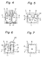
- a core having the shape of the helically-shaped intake port 6 is initially formed by using wooden molds. Then, the helically-shaped intake port 6 is formed in the cylinder head 3 by using the core thus formed.
- the straight lines P and Q indicate parting lines of the upper mold and the lower mold which are used when the core is formed. Therefore, from Figs. 4 through 7, it is understood that the core can be formed by the two split wooden molds.
- the core can be formed by the two aplit wooden molds, it is possible to easily from the helically-shaped intake port in the cylinder head.
- the inclined side wall in the inlet passage portion since the mixture flowing along the upper wall of the inlet passage portion can be speeded up when the engine is operating at a low speed under a heavy load, it is possible to create a strong swirl motion. Furthermore, when the engine is operating at a high speed under a heavy load, it is possible to obtain a high volumetric efficiency due to the inflow of the mixture from the bypass passage into the helical portion and due to the swirl motion suppressing operation caused by the inclined side wall.
Landscapes
- Engineering & Computer Science (AREA)
- Chemical & Material Sciences (AREA)
- Combustion & Propulsion (AREA)
- Mechanical Engineering (AREA)
- General Engineering & Computer Science (AREA)
- Cylinder Crankcases Of Internal Combustion Engines (AREA)
- Combustion Methods Of Internal-Combustion Engines (AREA)
Applications Claiming Priority (2)
| Application Number | Priority Date | Filing Date | Title |
|---|---|---|---|
| JP120634/81 | 1981-08-03 | ||
| JP56120634A JPS6032009B2 (ja) | 1981-08-03 | 1981-08-03 | ヘリカル型吸気ポ−ト |
Publications (3)
| Publication Number | Publication Date |
|---|---|
| EP0071949A2 true EP0071949A2 (de) | 1983-02-16 |
| EP0071949A3 EP0071949A3 (en) | 1984-01-11 |
| EP0071949B1 EP0071949B1 (de) | 1987-03-25 |
Family
ID=14791073
Family Applications (1)
| Application Number | Title | Priority Date | Filing Date |
|---|---|---|---|
| EP82106983A Expired EP0071949B1 (de) | 1981-08-03 | 1982-08-02 | Einlassvorrichtung für eine Brennkraftmaschine |
Country Status (6)
| Country | Link |
|---|---|
| US (1) | US4499868A (de) |
| EP (1) | EP0071949B1 (de) |
| JP (1) | JPS6032009B2 (de) |
| AU (1) | AU533872B2 (de) |
| CA (1) | CA1198330A (de) |
| DE (1) | DE3275846D1 (de) |
Cited By (6)
| Publication number | Priority date | Publication date | Assignee | Title |
|---|---|---|---|---|
| EP0072551A2 (de) * | 1981-08-19 | 1983-02-23 | Toyota Jidosha Kabushiki Kaisha | Einlasseinrichtung einer Brennkraftmaschine |
| EP0094084A2 (de) * | 1982-05-11 | 1983-11-16 | Toyota Jidosha Kabushiki Kaisha | Spiralförmiger Ansaugschlitz einer Brennkraftmaschine mit innerer Verbrennung |
| DE3316962A1 (de) * | 1982-05-11 | 1983-11-24 | Toyota Jidosha K.K., Toyota, Aichi | Schraubenfoermiger einlasskanal einer brennkraftmaschinen |
| EP0095185A2 (de) * | 1982-05-25 | 1983-11-30 | Toyota Jidosha Kabushiki Kaisha | Schraubenlinienförmiger Einlasskanal einer Brennkraftmaschine |
| EP0102453A1 (de) * | 1982-09-08 | 1984-03-14 | Toyota Jidosha Kabushiki Kaisha | Spiralförmiger Ansaugschlitz einer Brennkraftmaschine mit innerer Verbrennung |
| DE3435029A1 (de) * | 1984-02-06 | 1985-08-14 | Toyota Jidosha K.K., Toyota, Aichi | Luftansaugvorrichtung fuer eine brennkraftmaschine |
Families Citing this family (23)
| Publication number | Priority date | Publication date | Assignee | Title |
|---|---|---|---|---|
| JPS6153419A (ja) * | 1984-08-20 | 1986-03-17 | Toyota Motor Corp | 可変吸気スワ−ル方式の内燃機関の吸気制御方法 |
| AU588863B2 (en) * | 1985-03-18 | 1989-09-28 | Gregory, David James | Locking device |
| JPS6223756A (ja) * | 1985-07-24 | 1987-01-31 | Hitachi Electronics Eng Co Ltd | 印刷装置 |
| GB2188983B (en) * | 1985-08-23 | 1990-04-25 | Mitsubishi Motors Corp | Internal combustion engine having a variable swirl intake apparatus |
| US4930468A (en) * | 1989-04-06 | 1990-06-05 | Ford Motor Company | Ice with single intake valve and dual intake manifold runners |
| US5549088A (en) * | 1991-02-21 | 1996-08-27 | Yamaha Hatsudoki Kabushiki Kaisha | Induction system for engine |
| US5487365A (en) * | 1991-02-21 | 1996-01-30 | Yamaha Hatsudoki Kabushiki Kaisha | Induction system for engine |
| US5255649A (en) * | 1991-02-21 | 1993-10-26 | Yamaha Hatsudoki Kabushiki Kaisha | Intake air control system for the engine |
| US5359972A (en) * | 1991-02-21 | 1994-11-01 | Yamaha Hatsudoki Kabushiki Kasha | Tumble control valve for intake port |
| US5311848A (en) * | 1991-07-18 | 1994-05-17 | Yamaha Hatsudoki Kabushiki Kaisha | Induction system for engine |
| US5553590A (en) * | 1992-07-14 | 1996-09-10 | Yamaha Hatsudoki Kabushiki Kaisha | Intake control valve |
| US5267543A (en) * | 1992-12-21 | 1993-12-07 | Ford Motor Company | Dual induction system for internal combustion engine |
| EP0616116B1 (de) * | 1993-02-05 | 1998-07-22 | Yamaha Hatsudoki Kabushiki Kaisha | Ansaugsystem und Verfahren zum Betrieb eines Motors |
| US5671713A (en) * | 1995-03-09 | 1997-09-30 | Hitachi, Ltd. | Control device and apparatus for generating swirls in internal combustion engine |
| EP1130235B1 (de) * | 1993-07-09 | 2004-05-06 | Hitachi, Ltd. | Steuerungsvorrichtung für eine Brennkraftmaschine |
| JPH07119592A (ja) * | 1993-09-06 | 1995-05-09 | Yamaha Motor Co Ltd | 燃料噴射式2バルブエンジン |
| US5671712A (en) * | 1994-01-25 | 1997-09-30 | Yamaha Hatsudoki Kabushiki Kaisha | Induction system for engine |
| US5720255A (en) * | 1994-02-14 | 1998-02-24 | Yamaha Hatsudoki Kabushiki Kaisha | Control valve for multi-valve engine |
| JP3506769B2 (ja) * | 1994-06-14 | 2004-03-15 | ヤマハ発動機株式会社 | エンジンの吸気制御装置 |
| EP0688939B1 (de) * | 1994-06-15 | 1998-11-11 | Yamaha Hatsudoki Kabushiki Kaisha | Zylinderkopfanordnung für eine Mehrventil-Brennkraftmaschine mit obenliegender Nockenwelle |
| JPH0828284A (ja) * | 1994-07-20 | 1996-01-30 | Yamaha Motor Co Ltd | 4サイクルエンジンの吸気装置 |
| JPH0874585A (ja) * | 1994-08-31 | 1996-03-19 | Yamaha Motor Co Ltd | 4サイクルエンジンの吸気制御装置 |
| US10344705B2 (en) * | 2016-10-18 | 2019-07-09 | Ford Global Technologies, Llc | Intake valve fairing for a cylinder head of an engine |
Citations (5)
| Publication number | Priority date | Publication date | Assignee | Title |
|---|---|---|---|---|
| US2318914A (en) * | 1941-07-15 | 1943-05-11 | American Locomotive Co | Internal combustion engine |
| DE2803533A1 (de) * | 1978-01-27 | 1979-08-02 | Volkswagenwerk Ag | Luftverdichtende, selbstzuendende brennkraftmaschine |
| US4257384A (en) * | 1977-10-27 | 1981-03-24 | Yamaha Hatsukoki Kabushiki Kaisha | Intake control apparatus of engine |
| EP0068481A1 (de) * | 1981-06-29 | 1983-01-05 | Toyota Jidosha Kabushiki Kaisha | Vorrichtung zur Regelung einer Strömung in einem spiralförmigen Einlasskanal |
| EP0071272A2 (de) * | 1981-07-30 | 1983-02-09 | Toyota Jidosha Kabushiki Kaisha | Durchflussregler für eine spiralige Einlassöffnung einer Dieselmaschine |
Family Cites Families (13)
| Publication number | Priority date | Publication date | Assignee | Title |
|---|---|---|---|---|
| DE2059008A1 (de) * | 1970-12-01 | 1972-06-08 | Leonhard Schleicher | Drosselklappe fuer eine Rohrleitung |
| US3850479A (en) * | 1972-02-08 | 1974-11-26 | Fuller Co | Flow gate for a fluidizing gravity conveyor |
| AT336346B (de) * | 1972-03-31 | 1976-08-15 | List Hans | Einlasskanal fur brennkraftmaschinen |
| JPS6011864B2 (ja) * | 1976-04-19 | 1985-03-28 | ソニー株式会社 | 信号伝達装置 |
| DD143289A1 (de) * | 1976-09-01 | 1980-08-13 | Lothar Thon | Zylinderkopf fuer viertakt-brennkraftmaschinen |
| US4174686A (en) * | 1976-10-09 | 1979-11-20 | Toyo Kogyo Co., Ltd. | Intake system for internal combustion engines |
| JPS5947128B2 (ja) * | 1977-10-18 | 1984-11-16 | トヨタ自動車株式会社 | 内燃機関の吸気装置 |
| US4159011A (en) * | 1978-02-21 | 1979-06-26 | General Motors Corporation | Engine cylinder inlet port |
| JPS5823978Y2 (ja) * | 1978-02-24 | 1983-05-23 | 日産自動車株式会社 | 複式吸気機関の排気還流装置 |
| JPS6060007B2 (ja) * | 1978-05-22 | 1985-12-27 | トヨタ自動車株式会社 | カウンタフロ−型多気筒内燃機関の吸気装置 |
| JPS5920850B2 (ja) * | 1978-09-25 | 1984-05-16 | トヨタ自動車株式会社 | 内燃機関のヘリカル型吸気ポ−ト |
| JPS5654922A (en) * | 1979-10-12 | 1981-05-15 | Toyota Motor Corp | Suction device for internal combustion engine |
| JPS5768519A (en) * | 1980-10-17 | 1982-04-26 | Toyota Motor Corp | Suction device for internal combustion engine |
-
1981
- 1981-08-03 JP JP56120634A patent/JPS6032009B2/ja not_active Expired
-
1982
- 1982-07-30 CA CA000408460A patent/CA1198330A/en not_active Expired
- 1982-08-02 US US06/404,145 patent/US4499868A/en not_active Expired - Fee Related
- 1982-08-02 EP EP82106983A patent/EP0071949B1/de not_active Expired
- 1982-08-02 AU AU86683/82A patent/AU533872B2/en not_active Ceased
- 1982-08-02 DE DE8282106983T patent/DE3275846D1/de not_active Expired
Patent Citations (5)
| Publication number | Priority date | Publication date | Assignee | Title |
|---|---|---|---|---|
| US2318914A (en) * | 1941-07-15 | 1943-05-11 | American Locomotive Co | Internal combustion engine |
| US4257384A (en) * | 1977-10-27 | 1981-03-24 | Yamaha Hatsukoki Kabushiki Kaisha | Intake control apparatus of engine |
| DE2803533A1 (de) * | 1978-01-27 | 1979-08-02 | Volkswagenwerk Ag | Luftverdichtende, selbstzuendende brennkraftmaschine |
| EP0068481A1 (de) * | 1981-06-29 | 1983-01-05 | Toyota Jidosha Kabushiki Kaisha | Vorrichtung zur Regelung einer Strömung in einem spiralförmigen Einlasskanal |
| EP0071272A2 (de) * | 1981-07-30 | 1983-02-09 | Toyota Jidosha Kabushiki Kaisha | Durchflussregler für eine spiralige Einlassöffnung einer Dieselmaschine |
Cited By (9)
| Publication number | Priority date | Publication date | Assignee | Title |
|---|---|---|---|---|
| EP0072551A2 (de) * | 1981-08-19 | 1983-02-23 | Toyota Jidosha Kabushiki Kaisha | Einlasseinrichtung einer Brennkraftmaschine |
| EP0072551A3 (en) * | 1981-08-19 | 1984-03-07 | Toyota Jidosha Kabushiki Kaisha | An intake device of an internal combustion engine |
| EP0094084A2 (de) * | 1982-05-11 | 1983-11-16 | Toyota Jidosha Kabushiki Kaisha | Spiralförmiger Ansaugschlitz einer Brennkraftmaschine mit innerer Verbrennung |
| DE3316962A1 (de) * | 1982-05-11 | 1983-11-24 | Toyota Jidosha K.K., Toyota, Aichi | Schraubenfoermiger einlasskanal einer brennkraftmaschinen |
| EP0094084A3 (en) * | 1982-05-11 | 1984-03-07 | Toyota Jidosha Kabushiki Kaisha | A helically-shaped intake port of an internal combustion engine |
| EP0095185A2 (de) * | 1982-05-25 | 1983-11-30 | Toyota Jidosha Kabushiki Kaisha | Schraubenlinienförmiger Einlasskanal einer Brennkraftmaschine |
| EP0095185A3 (en) * | 1982-05-25 | 1984-02-08 | Toyota Jidosha Kabushiki Kaisha | A helically-shaped intake port of an internal-combustion engine |
| EP0102453A1 (de) * | 1982-09-08 | 1984-03-14 | Toyota Jidosha Kabushiki Kaisha | Spiralförmiger Ansaugschlitz einer Brennkraftmaschine mit innerer Verbrennung |
| DE3435029A1 (de) * | 1984-02-06 | 1985-08-14 | Toyota Jidosha K.K., Toyota, Aichi | Luftansaugvorrichtung fuer eine brennkraftmaschine |
Also Published As
| Publication number | Publication date |
|---|---|
| JPS5823224A (ja) | 1983-02-10 |
| EP0071949A3 (en) | 1984-01-11 |
| JPS6032009B2 (ja) | 1985-07-25 |
| AU533872B2 (en) | 1983-12-15 |
| CA1198330A (en) | 1985-12-24 |
| EP0071949B1 (de) | 1987-03-25 |
| DE3275846D1 (en) | 1987-04-30 |
| US4499868A (en) | 1985-02-19 |
| AU8668382A (en) | 1983-04-14 |
Similar Documents
| Publication | Publication Date | Title |
|---|---|---|
| EP0071949A2 (de) | Einlassvorrichtung für eine Brennkraftmaschine | |
| US4466395A (en) | Flow control device of a helically-shaped intake port | |
| EP0173014B1 (de) | Eine Einlassvorrichtung einer Brennkraftmaschine | |
| US4466394A (en) | Flow control device of a helically-shaped intake port | |
| US4485775A (en) | Helically-shaped intake port of an internal-combustion engine | |
| US4491102A (en) | Intake device of an internal combustion engine | |
| US4470386A (en) | Flow control device of a helically-shaped intake port | |
| US4503819A (en) | Helically-shaped intake port of an internal-combustion engine | |
| US4481915A (en) | Helically-shaped intake port of an internal combustion engine | |
| US4467750A (en) | Flow control device of a helically-shaped intake port | |
| US4478182A (en) | Helically-shaped intake port of an internal combustion engine | |
| US4485774A (en) | Helically-shaped intake port of an internal-combustion engine | |
| US4516544A (en) | Helically-shaped intake port of an internal-combustion engine | |
| US4502432A (en) | Helically shaped intake port of an internal-combustion engine | |
| US4481916A (en) | Helically-shaped intake port of an internal combustion engine | |
| US4457272A (en) | Flow control device of a helically-shaped intake port | |
| US4485773A (en) | Helically-shaped intake port of an internal-combustion engine | |
| US4466396A (en) | Flow control device of a helically-shaped intake port | |
| US4466397A (en) | Flow control device of a helically-shaped intake port | |
| JPH0244022Y2 (de) | ||
| JPS5828524A (ja) | ヘリカル型吸気ポ−トの流路制御装置 | |
| JPS6231619Y2 (de) | ||
| JPS5828530A (ja) | ヘリカル型吸気ポ−トの流路制御装置 | |
| JPS6238534B2 (de) | ||
| JPS6238541B2 (de) |
Legal Events
| Date | Code | Title | Description |
|---|---|---|---|
| PUAI | Public reference made under article 153(3) epc to a published international application that has entered the european phase |
Free format text: ORIGINAL CODE: 0009012 |
|
| 17P | Request for examination filed |
Effective date: 19820802 |
|
| AK | Designated contracting states |
Designated state(s): DE FR GB |
|
| PUAL | Search report despatched |
Free format text: ORIGINAL CODE: 0009013 |
|
| AK | Designated contracting states |
Designated state(s): DE FR GB |
|
| GRAA | (expected) grant |
Free format text: ORIGINAL CODE: 0009210 |
|
| AK | Designated contracting states |
Kind code of ref document: B1 Designated state(s): DE FR GB |
|
| REF | Corresponds to: |
Ref document number: 3275846 Country of ref document: DE Date of ref document: 19870430 |
|
| ET | Fr: translation filed | ||
| PLBE | No opposition filed within time limit |
Free format text: ORIGINAL CODE: 0009261 |
|
| STAA | Information on the status of an ep patent application or granted ep patent |
Free format text: STATUS: NO OPPOSITION FILED WITHIN TIME LIMIT |
|
| 26N | No opposition filed | ||
| PGFP | Annual fee paid to national office [announced via postgrant information from national office to epo] |
Ref country code: GB Payment date: 19950724 Year of fee payment: 14 |
|
| PGFP | Annual fee paid to national office [announced via postgrant information from national office to epo] |
Ref country code: FR Payment date: 19950809 Year of fee payment: 14 Ref country code: DE Payment date: 19950809 Year of fee payment: 14 |
|
| PG25 | Lapsed in a contracting state [announced via postgrant information from national office to epo] |
Ref country code: GB Effective date: 19960802 |
|
| GBPC | Gb: european patent ceased through non-payment of renewal fee |
Effective date: 19960802 |
|
| PG25 | Lapsed in a contracting state [announced via postgrant information from national office to epo] |
Ref country code: FR Effective date: 19970430 |
|
| PG25 | Lapsed in a contracting state [announced via postgrant information from national office to epo] |
Ref country code: DE Effective date: 19970501 |
|
| REG | Reference to a national code |
Ref country code: FR Ref legal event code: ST |