EP0071465B1 - Apparatus for charging insulating toner particles - Google Patents
Apparatus for charging insulating toner particles Download PDFInfo
- Publication number
- EP0071465B1 EP0071465B1 EP19820303973 EP82303973A EP0071465B1 EP 0071465 B1 EP0071465 B1 EP 0071465B1 EP 19820303973 EP19820303973 EP 19820303973 EP 82303973 A EP82303973 A EP 82303973A EP 0071465 B1 EP0071465 B1 EP 0071465B1
- Authority
- EP
- European Patent Office
- Prior art keywords
- toner particles
- roller
- charge
- toner
- charging
- Prior art date
- Legal status (The legal status is an assumption and is not a legal conclusion. Google has not performed a legal analysis and makes no representation as to the accuracy of the status listed.)
- Expired
Links
Images

Classifications
-
- G—PHYSICS
- G03—PHOTOGRAPHY; CINEMATOGRAPHY; ANALOGOUS TECHNIQUES USING WAVES OTHER THAN OPTICAL WAVES; ELECTROGRAPHY; HOLOGRAPHY
- G03G—ELECTROGRAPHY; ELECTROPHOTOGRAPHY; MAGNETOGRAPHY
- G03G15/00—Apparatus for electrographic processes using a charge pattern
- G03G15/06—Apparatus for electrographic processes using a charge pattern for developing
- G03G15/08—Apparatus for electrographic processes using a charge pattern for developing using a solid developer, e.g. powder developer
- G03G15/0806—Apparatus for electrographic processes using a charge pattern for developing using a solid developer, e.g. powder developer on a donor element, e.g. belt, roller
- G03G15/0812—Apparatus for electrographic processes using a charge pattern for developing using a solid developer, e.g. powder developer on a donor element, e.g. belt, roller characterised by the developer regulating means, e.g. structure of doctor blade
-
- G—PHYSICS
- G03—PHOTOGRAPHY; CINEMATOGRAPHY; ANALOGOUS TECHNIQUES USING WAVES OTHER THAN OPTICAL WAVES; ELECTROGRAPHY; HOLOGRAPHY
- G03G—ELECTROGRAPHY; ELECTROPHOTOGRAPHY; MAGNETOGRAPHY
- G03G2215/00—Apparatus for electrophotographic processes
- G03G2215/06—Developing structures, details
- G03G2215/0634—Developing device
- G03G2215/0636—Specific type of dry developer device
- G03G2215/0641—Without separate supplying member (i.e. with developing housing sliding on donor member)
Definitions
- This invention relates to an apparatus for electrostatically charging insulating toner particles.
- the apparatus is of the kind comprising a transport roller, a toner supply means for containing uncharged toner particles, and a charge injecting means, the transport roller being arranged to transport toner particles from the supply means through a charging zone in contact with the charge injecting means, and means for applying a voltage to the transport roller and to the charge injecting means.
- a transport roller for containing uncharged toner particles
- a charge injecting means the transport roller being arranged to transport toner particles from the supply means through a charging zone in contact with the charge injecting means, and means for applying a voltage to the transport roller and to the charge injecting means.
- electrostatographic images and more specifically xerographic images
- a developer composition comprised of toner particles and carrier particles is cascaded over an image bearing member, wherein the toner particles which are triboelectrically charged to a certain polarity and magnitude deposit in regions of the imaging surface where there is a preponderance of charge of opposite polarity.
- magnetic brush development magnetic carriers are employed, reference US-A-3 641 980, wherein magnetic forces are employed for the purpose of causing toner particles to deposit on the imaging member.
- magnetic brush development systems are more compact than cascade development systems, and do not depend on gravity for causing the toner particles to deposit on the imaging member surface, a factor which allows more freedom in locating the developer station.
- insulating toner particles are thus important for background control, and also such particles can be transferred rather efficiently and effectively from a photoresponsive surface to plain paper. While many different suitable methods are known for charging toner particles, there continues to be a need for an effective simple method for charging insulative toner particles, to a desired charge magnitude and a desired positive or negative charge polarity.
- US-A-3,166,432 there is disclosed the use of a conductive one component developer (toner and no carrier particles) for developing electrostatic charge patterns by bringing a conductive support member containing a layer of conductive toner particles into contact with the charge pattern.
- the toner particles are held to the support member primarily by Van der Waals forces, and the conductive support is maintained at a biased potential during development.
- the present invention is intended to provide an apparatus for charging insulative toner particles to either a positive polarity or a negative polarity.
- the invention accordingly provides an apparatus of the kind specified which is characterised in that the transport roller has an electrically resistive coating thereon, and that the charge injecting means, is positioned parallel to the circumference of the roller and spaced around a portion of the circumference of the roller, said portion being spaced from the toner supply means.
- the apparatus of the invention has the advantage that it provides a process for charging insulative toner particles while simultaneously controlling background development, and providing for the efficient and effective transfer of such toner particles from an image bearing surface to plain paper.
- the present invention is directed to an improved apparatus for charging uncharged insulating toner particles, which apparatus comprises in operative relationship a roller means containing a coating thereon, a toner supply means containing therein uncharged insulating toner particles, a charge injecting means, a voltage source means for the charge injecting means, and a voltage source means for the roller means, wherein charges are injected from the charge injecting means into the uncharged insulating toner particles deposited on the roller means, the injection being accomplished in a charging zone encompassed by the roller means and the charge injecting means.
- the present invention is directed to a process for charging insulating uncharged toner particles contained on a roller means, to a positive or negative polarity by injecting the appropriate charges thereon, or therein from charges originating from a charge injecting electrode means which contacts toner particles contained in a zone between the roller means and the electrode means, the polarity of the charges contained on the insulating toner particles being dependent on the polarity of the charges supplied to the charging electrode by a voltage source means.
- the thus charged insulating toner particles can be employed in electrostatographic imaging systems, particularly xerographic imaging systems. Accordingly, in accordance with the process of the present invention and the apparatus thereof, toner particles can be charged to the desired polarity without the utilization of carrier particles as is customarily practiced in the prior art.
- an improved electrostatographic imaging apparatus comprising a charging means, an imaging means, a development means, a transfer means, a fusing means, an optional cleaning means and a fixing means, the improvement residing in the development means which comprise in operative relationship a roller means, containing a coating thereon, a toner supply means containing therein uncharged insulating toner particles, a charge injecting means, a voltage source means, for said charge injecting means, a voltage source means for said roller means, wherein charges are injected from said charge injecting means into the uncharged insulating toner particles deposited on said roller means, said injection accomplished in a charging zone encompassed by said roller means and said charge injecting means, and wherein the resulting charged insulating toner particles are deposited on an imaging member.
- FIG. 1 Illustrated in Figure 1 is the apparatus and process of the present invention generally designated 7 comprising an imaging member means 10, a roller means 12, containing thereon coating 13, toner supply reservoir means 14, containing therein uncharged insulating toner particles 24, a charging electrode means 16, a pressure blade means 17, a voltage source means 18, a voltage source means 20, and charging zone 19.
- the uncharged insulating toner particles 24 are metered onto the roller means 12 as the roll moves in the direction illustrated by the arrow, the amount of toner particles being deposited on said roll dependent primarily on the spacing between the toner supply reservoir 14 and roller 12.
- the toner supply reservoir thus functions similar to a doctor blade and is maintained at a specific angle and at a sufficient pressure so as to provide uncharged insulating toner particles on the roller means 12 in a thickness of from about 12 to about 50 pm, and preferably from about 12 to about 25 pm, or preferably about 1 layer of toner particles.
- the insulating toner particles are adhered to the roller means 12 by electrostatic attraction forces, the roller being caused to rotate by a motor not shown.
- the insulating toner particles 24 migrate on the roller means 12, they eventually contact the charged injecting electrode means 16 in a charging zone 19 wherein charges of a positive polarity as illustrated, or a negative polarity not illustrated, are injected into the toner particles; accordingly, the toner particles 24' exiting from the charging zone 19 contain thereon positive charges.
- the charging electrode means 16 is self-spaced from the roller means 12 by the toner particles situated therebetween, and the voltage source, 18, V c , supplies the charge to the electrode 16, which charge in the embodiment shown is of a positive polarity.
- the positively charged toner particles continue to migrate on the roller means 12, until they contact the latent image contained on the imaging member means 10, wherein they are electrostatically attracted to the image, causing development.
- Unused charged toner particles are returned to the toner supply reservoir 14 on the roller means 12 as shown.
- the blade 17 provides sufficient pressure to the imaging member means 10 so as to cause said imaging member means to be in constant contact with the charged insulating toner particles as shown.
- Voltage, 20, V B also assists in providing for attraction between the charged toner particles and the image contained on the imaging member 10.
- An important feature of the present invention resides in the charging electrode means 16, which electrode injects positive charges, or negative charges into the insulating toner particles 24 contained on the roller means 12.
- the polarity of the charge, and the magnitude of charge injected is controlled by the voltage source V c 18, thus if a positive polarity is desired on the toner particles, a positive voltage source is applied to the injecting contact means 16, while if a negative polarity is desired on the insulating toner particles, a negative voltage V c is applied to the charging electrode means 16.
- Charges of the appropriate polarity and magnitude are injected into and accepted by the insulating toner particles as a result of the contact between such particles and the injecting electrode means 16, which is self-spaced from the roller means 12 by the insulating toner particles situated in the charging zone 19.
- the roller means 12 generally only one layer of toner particles is contained on the roller means 12, although less or more than one layer of toner particles can be present on roller 12, however, if several layers of uncharged toner particles are contained on the roller means 12, difficulties can be encountered in completely charging all the layers of toner particles, since the charged being injected by the electrode 16 cannot usually penetrate more than a few layers of toner particles.
- the resulting charged insulating toner particles can easily be transferred to plain bond paper subsequent to development as contrasted with conductive toner particles which contain conducting agents therein, and are very difficult to transfer to plain bond paper.
- the roller means 12 is comprised of a core which can be hollow or solid and is comprised of numerous known suitable materials including for example, aluminum, steel, iron, polymeric materials, and the like, providing they are of sufficient strength to be operable in the system, with the preferred core material being aluminum.
- this roll has a diameter of from about 2.5 cm to about 7.5 cm and preferably has a diameter of from 2.5 cm to 5.0 cm.
- This roll can be of a larger or small diameter providing it accomplishes the objectives of the present invention.
- the roller means 12 contains thereon a resistive textured coating layer 13 such as aluminized Mylar (registered trade mark) overcoated with carbon black, Krylon ultra flat black paint, commercially available as Krylon 1602, and various other similar resistive materials.
- the thickness of the coating can vary over a wide range and is dependent on many factors including economical considerations, however, generally the thickness of this coating is from about 2.5 to about 125 pm; preferably is from about 25 to about 75 pm. While it is not desired to be limited by theory, it is believed that the coating assists in increasing the efficiency of charge injection from the charge injecting electrode 16, in that for example, negative charges, which would tend to neutralize the positive charges of the charged toner particles contained on the charging roll 12 are prevented from being attracted to the positively charged toner particles. Similarly, when a negative charge is injected into the insulating toner particles, a corresponding positive charge results on the roller means 12, and it is desired to prevent such a charge from migrating to the negatively charged toner particles.
- the amount of charge applied to the uncharged insulating toner particles is primarily dependent on the voltage source 18 V e , which charge generally ranges from about 100 volts to about 500 volts, and preferably from about 200 volts to about 300 volts when a positive polarity is desired on the insulating uncharged toner particles.
- the voltage V c 18 is from about a -100 volts to about a -500 volts, and preferably from about a -200 volts to about a -300 volts.
- the charge injected into the uncharged toner particles is not only dependent on the voltage source 18 V c but on a number of other factors including for example, the number of layers of particles charged, the material utilized as coating 13, and the like.
- the uncharged toner particles acquire a charge of from about 10 microcoulombs per gram to about 35 microcoulombs per gram, and preferably from about 10 microcoulombs per gram to about 20 microcoulombs per gram.
- Such toner particles are thus of sufficient conductivity so as to be attracted to the image contained on the imaging member means 10, but yet sufficiently insulating in order that they may be easily transferable to plain bond paper.
- the voltage source 20, V B which is primarily employed for background control in the image areas in that it prevents deposition of the charged insulating toner particles in the background areas ranges from about -75 volts to about -200 volts and preferably ranges from about -75 volts to about -150 volts.
- the injecting electrode means 16 can be comprised of various suitable materials providing it is capable of accepting charge from the voltage source 18 V c , and further, such electrode means 16 should be comprised of a material that will enable the injection of positive or negative charges from the injecting source means 16 into the uncharged insulating toner particles in accordance with the features of the present invention.
- the injecting or charging electrode can be comprised of metallic substances such as aluminum, steel, iron and the like, with aluminum being preferred.
- the charging electrode means 16 is usually not maintained in a fixed position, rather it generally contains thereon a foam backing which is not shown, so as to allow it to contact the roller means 12, which contact is usually prevented by the layer of insulating uncharged toner particles contained between the charge injecting means 16 and the roller means 12.
- the charging electrode means 16 is self-spaced from the roller means 12, such self-spacing being dependent on the number of layers of toner particles contained in the charging zone 19.
- the length of the charging zone 19 can vary providing the objectives of the present invention are accomplished, generally however, this length is from about 5 millimeters to about 30 millimeters, and preferably from about 10 millimeters to about 20 millimeters.
- roller means 12 can be as shown, that is, in the same direction, or in a direction opposite to each other, that is, roller 12 can move in the direction opposite to that of the direction of movement of imaging member means 10.
- roller means 12 is moving at a rate of speed that is faster than the rate of speed of movement of the imaging member means 10, thus the speed ratio of the charging roll 12 to the imaging member means 10 varies from about 4to about 1 and is preferably from about 2 to about 3. Accordingly thus, in this embodiment, the roller 12 is moving at a higher speed (4) than the speed of the imaging member means 10.
- the pressure blade 17 can be comprised of numerous suitable materials including plastics, nylon (registered trade mark), steel, aluminum and the like with the force being exerted by such blade being of sufficient value so as to maintain the imaging member 10 in contact with the charged insulating toner particles, such force ranging generally from about 0.05 to about 0.5 Kg. cm- 1 and preferably from about 0.09 to about 0.18 Kg. cm - 1 .
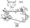
- FIG. 2 there is illustrated a xerographic imaging system employing an imaging member 1, which corresponds to the imaging member 10 of Figure 1.
- the imaging member 1 can be comprised of a substrate, overcoated with a transport layer containing N,N,N',N' - tetraphenyl - [1,1' - biphenyl] 4,4'-diamine; or similar diamines dispersed in a polycarbonate, which in turn is overcoated with a charge generating layer of trigonal selenium.
- Imaging member 1 moves in the direction of arrow 27 to advance successive portions of the imaging member sequentially through the various processing stations disposed about the path of movement thereof.
- the imaging member is entrained about a sheet-stripping roller 28, tensioning means 29, and drive roller 30.
- Tensioning means 29 includes a roller 31 having flanges on opposite sides thereof to define a path through which member 1 moves, with roller 31 being mounted on each end of guides attached to springs 22. Springs 22 are tensioned such that roller 31 presses against the imaging belt member 1. In this manner, member 1 is placed under the desired tension. The level of tension is relatively low permitting member 1 to be easily deformed.
- drive roller 30 is mounted rotatably and in engagement with member 1.
- Roller 30 rotates roller 30 to advance member 1 in the direction of arrow 27.
- Roller 30 is coupled to motor 33 by suitable means such as a belt drive.
- Sheet-stripping roller 28 is freely rotatable so as to readily permit member 1 to move in the direction of arrow 27 with a minimum of friction.
- a corona generating device indicated generally by the reference numeral 34, charges the photoconductive surface of imaging member 1 to a relatively high, substantially uniform potential.
- the charged portion of the photoconductive surface is then advanced through exposure station I.
- An original document 35 is positioned face down upon transparent platen 36.
- Lamps 37 flash light rays onto original document 35, and the light rays reflected from original document 35 are transmitted through lens 38 forming light image thereof.
- Lens 38 focuses the light image onto the charged portion of the photoconductive surface to selectively dissipate the charge thereon. This records an electrostatic latent image on the photoconductive surface which corresponds to the informational areas contained within original document 35.
- imaging member 1 advances the electrostatic latent image recorded thereon to station J wherein it is contacted with positively charged insulating toner particles 24', station J including a roller means 12, coating 13, a charging injecting means 16, a toner supply reservoir 14, pressure blade 17, charging zone 19, and insulating toner particles 24.
- station J including a roller means 12, coating 13, a charging injecting means 16, a toner supply reservoir 14, pressure blade 17, charging zone 19, and insulating toner particles 24.
- Imaging member 1 then advances the toner powder image to transfer station K.
- a sheet of support material 44 is moved into contact with the toner powder image.
- the sheet of support material 44 is advanced to transfer station K by a sheet feeding apparatus (not shown).
- the sheet feeding apparatus includes a feed roll contacting the uppermost sheet of a stack of sheets. The feed roll rotates so as to advance the uppermost sheet from the stack into a chute, which chute directs the advancing sheet of support material into contact with the photoconductive surface of member 1 in a time sequence in order that the toner powder image developed thereon contacts the advancing sheet of support material at transfer station K.
- Transfer station K includes a corona generating device 46 which sprays ions onto the backside of sheet 44, allowing for the attraction of the toner powder image from the photoconductive surface to sheet 44. After transfer, sheet 44 moves in the direction of arrow 48 onto a conveyor (not shown) which advances sheet 44 to fusing station L.
- Fusing station L includes a fuser assembly, indicated generally by the reference numeral 50, which permanently affixes the transferred toner powder image to sheet 44.
- fuser assembly 50 includes a heated fuser roller 52 and a back-up roller 54.
- Sheet 44 passes between fuser roller 52 and back-up roller 54 with the toner powder image contacting fuser roller 52. In this manner, the toner powder image is permanently affixed to sheet 44.
- a chute guides the advancing sheet 44 to a catch tray for subsequent removal from the printing machine.
- Cleaning station L includes a rotatably mounted fibrous: brush 56 in contact with the photoconductive surface. The particles are cleaned from the photoconductive surface by the rotation of brush 56 in contact therewith. Subsequent to cleaning, a discharge lamp (not shown) floods photoconductive surface 12 with light to dissipate any residual electrostatic charge remaining thereon prior to the charging thereof for the next successive imaging cycle.
- Illustrative examples of the imaging member 1 or 10 include inorganic and organic photoresponsive materials such as amorphous selenium, selenium alloys, including alloys of selenium-tellurium, selenium arsenic, selenium antimony, selenium-tellurium-arsenic, cadmium sulfide, zinc oxide, polyvinylcarbazole, layered organic photoreceptors, such as those containing as an injecting contact, carbon dispersed in a polymer, overcoated with a transport layer, which in turn is overcoated with a generating layer, and finally an overcoating of an insulating organic resin, reference U.S. Pat 4,251,612, overcoated layers comprises of a substrate, a charge transport layer, and a charge generating layer, reference U.S. Patent 4,265,990 and the like.
- inorganic and organic photoresponsive materials such as amorphous selenium, selenium alloys, including alloys of selenium-tellurium, seleni
- organic photoreceptor materials include, 4 - dimethylaminobenzylidene; benzhydrazide; 2 - benzylidene - amino - carbazole, 4 - dimethyl - amino - benzylidene, 2 - benzylidene - amino - carbazole, (2 - nitro - benzylidene) - p - bromo - aniline; 2,4 - diphenyl quinazoline; 1,2,4 - triazine; 1,5 - diphenyl - 3 - methyl pyrazoline 2 - (4' - dimethyl - amino phenyl)benzoxazole; 3 -amino carbazole; polyvinylcarbazole - trinitro - fluorenone charge transfer complexes; phthalocyanines, mixtures thereof, and the like.
- positively charged toner compositions are employed when the photoreceptor is charged negatively as is the situation with most organic photoreceptors, while negatively charged toner particles are employed when the photoreceptor is charged positively, as is the situation with most inorganic photoreceptors such as selenium.
- insulating toner resin materials that can be utilized include for example poJyamides, epoxies, polyurethanes, vinyl resins and polymeric esterification products of a dicarboxylic acid and a diol comprising a diphenol.
- Suitable vinyl resins can be employed in the toners of the present system including homopolymers or copolymer of two or more vinyl monomers.
- vinyl monomeric units include: styrene, p-chlorostyrene vinyl naphthalene, ethylenically unsaturated mono-olefins such as ethylene, propylene, butylene, isobutylene and the like; vinyl esters such as vinyl chloride, vinyl bromide, vinyl fluoride, vinyl acetate, vinyl propionate, vinyl benzoate, vinyl butyrate and the like; esters of alphamethylene aliphatic monocarboxylic acids such as methyl acrylate, ethyl arylate, n-butylacrylate, isobutyl arylate, dodecyl acrylate, n-octyl acrylate, 2-chloroethyl acrylate, phenyl acrylate, methylalphachloroacrylate, methyl metharylate, ethyl metharylate, butyl methacrylate and the like; acrylonitrile, methacryl
- toner resins containing a relatively high percentage of styrene are preferred since greater image definition and density is usually obtained with their use.
- the styrene resin employed may be a homopolymer of styrene or styrene homologs of copolymers of styrene with other monomeric groups containing a single methylene group attached to a carbon atom by a double bond. Any of the above typical monomeric units may be copolymerized with styrene by addition polymerization.
- Styrene resins may also be formed by the polymerization of mixtures of two or more unsaturated monomeric materials with a styrene monomer.
- the addition polymerization technique employed embraces known polymerization techniques such as free radical, anionic and cationic polymerization processes. Any of these vinyl resins may be blended with one or more resins if desired, preferably other vinyl resins which insure good triboelectric properties and uniform resistance against physical degradation. However, non-vinyl type thermoplastic resins may also be employed including resin modified phenolformaldehyde resins, oil modified epoxy resins, polyurethane resins, cellulosic resins, polyether resins and mixtures thereof.
- esterification products of a dicarboxylic acid and a diol comprising a diphenol may be used as a preferred resin material for the toner composition of the present invention.
- These materials are illustrated in U.S. 3,655,374, the disclosure of which is totally incorporated herein by reference, the diphenol reactant being of the formula as shown in column 4, beginning at line 5 of this patent and the dicarboxylic acid being of the formula as shown in column 6 of the above patent.
- Optimum electrophotographic resins result from styrene butylmethacrylate copolymers, styrene vinyl toluene copolymers, styrene acrylate copolymers, polyester resins, predominantly styrene or polystyrene based resins as generally described in U.S. Reissue 24,136 and polystyrene blends as described in US-A-2,788,288.
- the toner resin particles can vary in diameter but generally range from about 5 pm to about 30 pm, and preferably from about 10 11m to about 20 pm.
- the toner resin is present in an amount so that the total of all ingredients total about 100 percent, thus when 5 percent by weight of an alkyl pyridinium compound is present and 10 percent by weight of pigment such as carbon black is present, about 85 percent by weight of resin material is used.
- the colorant for the toner particles may be employed as the colorant for the toner particles, such materials being well known, and including for example, carbon black, nigrosine dye, aniline blue, calco oilblude, chrome yellow, ultramarine blue, DuPont oil red, methylene blue chloride, phthalocyanine blue and mixtures thereof.
- the pigment or dye should be present in sufficient quantity to render it highly colored so that it will form a clearly visible image on the recording member.
- the toner may comprise a black pigment such a carbon black or a black dye such as amaplast black dye available from the National Aniline Products Inc.
- the pigment is employed in various amounts from about 3 percent to about 20 percent by weight based on the total weight of toner, however, if the toner colorant employed is a dye, substantially smaller quantities may be used.
- the toner resin may contain a magnetic material, such as the magnetite Mapico Black, as a substitute for the colorant, or in addition thereto, thereby resulting in a magnetic toner.
- a magnetic material such as the magnetite Mapico Black
- the magnetite is present in an amount of from about 40 percent by weight to about 80 percent by weight, and preferably from about 50 percent by weight to about 70 percent by weight.
- the insulating toner particles can contain charge enhancing additives, such as quaternary ammonium compounds, alkyl pyridinium compounds, like cetyl pyridinium chloride, and the like.
- the charge enhancing additives which are present in an amount of from about 0.5 percent by weight to about 10 percent by weight, generally impart a positive charge to the toner resin, and thus are primarily useful only in those situations where the toner particles are being positively charged by the injecting electrode.
- insulating toner particles comprised in operative relationship of means for transporting insulating toner particles, and a means for injecting charges into the insulating toner particles, the means for transporting, and the means for injecting being charged to a predetermined potential. Subsequently the charged toner particles can be deposited on a flexible or rigid imaging member contained in an electrostatographic imaging device, as illustrated herein.
Landscapes
- Physics & Mathematics (AREA)
- General Physics & Mathematics (AREA)
- Dry Development In Electrophotography (AREA)
- Developing Agents For Electrophotography (AREA)
Description
- This invention relates to an apparatus for electrostatically charging insulating toner particles. The apparatus is of the kind comprising a transport roller, a toner supply means for containing uncharged toner particles, and a charge injecting means, the transport roller being arranged to transport toner particles from the supply means through a charging zone in contact with the charge injecting means, and means for applying a voltage to the transport roller and to the charge injecting means. Such an apparatus is described in US-A-4 194 830. The invention is particularly, although not exclusively, concerned with such an apparatus used in an electrostatographic apparatus for the development of electrostatic latent images.
- The formation and development of electrostatographic images, and more specifically xerographic images, is well known in the art as described for example in US-A-2 297 691. In one known method for causing the development of such images, a developer composition comprised of toner particles and carrier particles is cascaded over an image bearing member, wherein the toner particles which are triboelectrically charged to a certain polarity and magnitude deposit in regions of the imaging surface where there is a preponderance of charge of opposite polarity. In another form of development known as magnetic brush development, magnetic carriers are employed, reference US-A-3 641 980, wherein magnetic forces are employed for the purpose of causing toner particles to deposit on the imaging member. In addition to providing for the superior development of solid image areas, magnetic brush development systems are more compact than cascade development systems, and do not depend on gravity for causing the toner particles to deposit on the imaging member surface, a factor which allows more freedom in locating the developer station.
- In developer mixtures used in conventional cascade development systems, there is a triboelectric charging relationship between the toner particles and the carrier particles, thus for example, the toner particles are charged negatively, and the carrier particles are charged positively, accordingly, positively and negatively charged images cannot easily be rendered visible with the same developer. Also, the triboelectric properties of the toner composition while necessary for development can cause problems, for example, uneven charging of the toner causes background deposits, as the forces between the carrier and toner particles result in various threshold levels from toner particle to toner particle. Further, since the toner particles retain their charge for extended periods of time, any toner that escapes the development zone and enters into other parts of the electrostatographic apparatus can cause mechanical problems. While magnetic brush development overcomes some of the problems encountered with cascade development, it is in some instances less efficient in that it requires triboelectrically charged toners.
- There has also been described in the prior art magnetic development systems and materials wherein carrier particles are not utilized, that is, one component developer compositions. One such system is described in US-A-2,846,333, which patent discloses the use of a magnetic brush to apply toner particles formed of magnetite and resin materials. One difficulty encountered with this process is that the relatively high electrical conductivity of the toner particles renders electrostatic transfer rather difficult. Also there is described in US-A-3,909,258 electrostatic development utilizing magnetic brush and no carrier particles. The developing composition used in such systems is comprised of toner particles, reference US-A-3,639,245. One disadvantage of such a toner composition is that it does not transfer efficiently from a photoconductive substrate to plain bond paper.
- Most single component development systems control background deposition with magnetic forces, and as such forces are generally weaker than electrostatic forces, background development from single component systems is typically inferior to electrostatic systems employing two component developer compositions. Additionally, many single component development systems use conductive toner charged by induction, however, conductive toner usually requires special papers and the like.
- The utilization of insulating toner particles is thus important for background control, and also such particles can be transferred rather efficiently and effectively from a photoresponsive surface to plain paper. While many different suitable methods are known for charging toner particles, there continues to be a need for an effective simple method for charging insulative toner particles, to a desired charge magnitude and a desired positive or negative charge polarity.
- Other development methods include powder cloud development as described in US-A-2,217,776 and touchdown development as described in US-A-3,166,432. In US-A-3,166,432 there is disclosed the use of a conductive one component developer (toner and no carrier particles) for developing electrostatic charge patterns by bringing a conductive support member containing a layer of conductive toner particles into contact with the charge pattern. The toner particles are held to the support member primarily by Van der Waals forces, and the conductive support is maintained at a biased potential during development.
- The present invention is intended to provide an apparatus for charging insulative toner particles to either a positive polarity or a negative polarity.
- The invention, accordingly provides an apparatus of the kind specified which is characterised in that the transport roller has an electrically resistive coating thereon, and that the charge injecting means, is positioned parallel to the circumference of the roller and spaced around a portion of the circumference of the roller, said portion being spaced from the toner supply means.
- The apparatus of the invention has the advantage that it provides a process for charging insulative toner particles while simultaneously controlling background development, and providing for the efficient and effective transfer of such toner particles from an image bearing surface to plain paper.
- In one embodiment, the present invention is directed to an improved apparatus for charging uncharged insulating toner particles, which apparatus comprises in operative relationship a roller means containing a coating thereon, a toner supply means containing therein uncharged insulating toner particles, a charge injecting means, a voltage source means for the charge injecting means, and a voltage source means for the roller means, wherein charges are injected from the charge injecting means into the uncharged insulating toner particles deposited on the roller means, the injection being accomplished in a charging zone encompassed by the roller means and the charge injecting means.
- In another embodiment the present invention is directed to a process for charging insulating uncharged toner particles contained on a roller means, to a positive or negative polarity by injecting the appropriate charges thereon, or therein from charges originating from a charge injecting electrode means which contacts toner particles contained in a zone between the roller means and the electrode means, the polarity of the charges contained on the insulating toner particles being dependent on the polarity of the charges supplied to the charging electrode by a voltage source means. The thus charged insulating toner particles can be employed in electrostatographic imaging systems, particularly xerographic imaging systems. Accordingly, in accordance with the process of the present invention and the apparatus thereof, toner particles can be charged to the desired polarity without the utilization of carrier particles as is customarily practiced in the prior art.
- In accordance with another feature of the present invention, there is provided an improved electrostatographic imaging apparatus comprising a charging means, an imaging means, a development means, a transfer means, a fusing means, an optional cleaning means and a fixing means, the improvement residing in the development means which comprise in operative relationship a roller means, containing a coating thereon, a toner supply means containing therein uncharged insulating toner particles, a charge injecting means, a voltage source means, for said charge injecting means, a voltage source means for said roller means, wherein charges are injected from said charge injecting means into the uncharged insulating toner particles deposited on said roller means, said injection accomplished in a charging zone encompassed by said roller means and said charge injecting means, and wherein the resulting charged insulating toner particles are deposited on an imaging member.
- The present invention and various alternative embodiments thereof will now be described with reference to the Figures wherein:
- Figure 1 is an elevational view illustrating the development apparatus and development process of the present invention.
- Figure 2 illustrates the use of the apparatus and process of the present invention in a conventional electrostatographic imaging system.
- Illustrated in Figure 1 is the apparatus and process of the present invention generally designated 7 comprising an imaging member means 10, a roller means 12, containing thereon
coating 13, toner supply reservoir means 14, containing therein unchargedinsulating toner particles 24, a charging electrode means 16, a pressure blade means 17, a voltage source means 18, a voltage source means 20, andcharging zone 19. The unchargedinsulating toner particles 24 are metered onto the roller means 12 as the roll moves in the direction illustrated by the arrow, the amount of toner particles being deposited on said roll dependent primarily on the spacing between thetoner supply reservoir 14 androller 12. The toner supply reservoir thus functions similar to a doctor blade and is maintained at a specific angle and at a sufficient pressure so as to provide uncharged insulating toner particles on the roller means 12 in a thickness of from about 12 to about 50 pm, and preferably from about 12 to about 25 pm, or preferably about 1 layer of toner particles. The insulating toner particles are adhered to the roller means 12 by electrostatic attraction forces, the roller being caused to rotate by a motor not shown. As theinsulating toner particles 24 migrate on the roller means 12, they eventually contact the charged injecting electrode means 16 in acharging zone 19 wherein charges of a positive polarity as illustrated, or a negative polarity not illustrated, are injected into the toner particles; accordingly, the toner particles 24' exiting from thecharging zone 19 contain thereon positive charges. The charging electrode means 16 is self-spaced from the roller means 12 by the toner particles situated therebetween, and the voltage source, 18, Vc, supplies the charge to theelectrode 16, which charge in the embodiment shown is of a positive polarity. The positively charged toner particles continue to migrate on the roller means 12, until they contact the latent image contained on the imaging member means 10, wherein they are electrostatically attracted to the image, causing development. Unused charged toner particles are returned to thetoner supply reservoir 14 on the roller means 12 as shown. The blade 17 provides sufficient pressure to the imaging member means 10 so as to cause said imaging member means to be in constant contact with the charged insulating toner particles as shown. Voltage, 20, VB, also assists in providing for attraction between the charged toner particles and the image contained on theimaging member 10. - An important feature of the present invention resides in the charging electrode means 16, which electrode injects positive charges, or negative charges into the
insulating toner particles 24 contained on the roller means 12. The polarity of the charge, and the magnitude of charge injected is controlled by thevoltage source V c18, thus if a positive polarity is desired on the toner particles, a positive voltage source is applied to the injecting contact means 16, while if a negative polarity is desired on the insulating toner particles, a negative voltage Vc is applied to the charging electrode means 16. Charges of the appropriate polarity and magnitude are injected into and accepted by the insulating toner particles as a result of the contact between such particles and the injecting electrode means 16, which is self-spaced from the roller means 12 by the insulating toner particles situated in thecharging zone 19. As indicated herein, generally only one layer of toner particles is contained on the roller means 12, although less or more than one layer of toner particles can be present onroller 12, however, if several layers of uncharged toner particles are contained on the roller means 12, difficulties can be encountered in completely charging all the layers of toner particles, since the charged being injected by theelectrode 16 cannot usually penetrate more than a few layers of toner particles. The resulting charged insulating toner particles can easily be transferred to plain bond paper subsequent to development as contrasted with conductive toner particles which contain conducting agents therein, and are very difficult to transfer to plain bond paper. - The roller means 12 is comprised of a core which can be hollow or solid and is comprised of numerous known suitable materials including for example, aluminum, steel, iron, polymeric materials, and the like, providing they are of sufficient strength to be operable in the system, with the preferred core material being aluminum. Generally, this roll has a diameter of from about 2.5 cm to about 7.5 cm and preferably has a diameter of from 2.5 cm to 5.0 cm. This roll can be of a larger or small diameter providing it accomplishes the objectives of the present invention.
- The roller means 12 contains thereon a resistive
textured coating layer 13 such as aluminized Mylar (registered trade mark) overcoated with carbon black, Krylon ultra flat black paint, commercially available as Krylon 1602, and various other similar resistive materials. The thickness of the coating can vary over a wide range and is dependent on many factors including economical considerations, however, generally the thickness of this coating is from about 2.5 to about 125 pm; preferably is from about 25 to about 75 pm. While it is not desired to be limited by theory, it is believed that the coating assists in increasing the efficiency of charge injection from thecharge injecting electrode 16, in that for example, negative charges, which would tend to neutralize the positive charges of the charged toner particles contained on thecharging roll 12 are prevented from being attracted to the positively charged toner particles. Similarly, when a negative charge is injected into the insulating toner particles, a corresponding positive charge results on the roller means 12, and it is desired to prevent such a charge from migrating to the negatively charged toner particles. - The amount of charge applied to the uncharged insulating toner particles is primarily dependent on the voltage source 18 Ve, which charge generally ranges from about 100 volts to about 500 volts, and preferably from about 200 volts to about 300 volts when a positive polarity is desired on the insulating uncharged toner particles. When a negative polarity is desired on the uncharged insulating toner particles, the
voltage V c18 is from about a -100 volts to about a -500 volts, and preferably from about a -200 volts to about a -300 volts. - The charge injected into the uncharged toner particles is not only dependent on the voltage source 18 Vc but on a number of other factors including for example, the number of layers of particles charged, the material utilized as
coating 13, and the like. However, generally the uncharged toner particles acquire a charge of from about 10 microcoulombs per gram to about 35 microcoulombs per gram, and preferably from about 10 microcoulombs per gram to about 20 microcoulombs per gram. Such toner particles are thus of sufficient conductivity so as to be attracted to the image contained on the imaging member means 10, but yet sufficiently insulating in order that they may be easily transferable to plain bond paper. - The
voltage source 20, VB, which is primarily employed for background control in the image areas in that it prevents deposition of the charged insulating toner particles in the background areas ranges from about -75 volts to about -200 volts and preferably ranges from about -75 volts to about -150 volts. - The injecting electrode means 16 can be comprised of various suitable materials providing it is capable of accepting charge from the voltage source 18 Vc, and further, such electrode means 16 should be comprised of a material that will enable the injection of positive or negative charges from the injecting source means 16 into the uncharged insulating toner particles in accordance with the features of the present invention. Generally, the injecting or charging electrode can be comprised of metallic substances such as aluminum, steel, iron and the like, with aluminum being preferred. The charging electrode means 16 is usually not maintained in a fixed position, rather it generally contains thereon a foam backing which is not shown, so as to allow it to contact the roller means 12, which contact is usually prevented by the layer of insulating uncharged toner particles contained between the charge injecting means 16 and the roller means 12. Thus, the charging electrode means 16 is self-spaced from the roller means 12, such self-spacing being dependent on the number of layers of toner particles contained in the charging
zone 19. The length of the chargingzone 19 can vary providing the objectives of the present invention are accomplished, generally however, this length is from about 5 millimeters to about 30 millimeters, and preferably from about 10 millimeters to about 20 millimeters. - The direction of movement of the roller means 12 and the imaging member means 10 can be as shown, that is, in the same direction, or in a direction opposite to each other, that is,
roller 12 can move in the direction opposite to that of the direction of movement of imaging member means 10. Generally, roller means 12 is moving at a rate of speed that is faster than the rate of speed of movement of the imaging member means 10, thus the speed ratio of the chargingroll 12 to the imaging member means 10 varies from about 4to about 1 and is preferably from about 2 to about 3. Accordingly thus, in this embodiment, theroller 12 is moving at a higher speed (4) than the speed of the imaging member means 10. - The pressure blade 17 can be comprised of numerous suitable materials including plastics, nylon (registered trade mark), steel, aluminum and the like with the force being exerted by such blade being of sufficient value so as to maintain the
imaging member 10 in contact with the charged insulating toner particles, such force ranging generally from about 0.05 to about 0.5 Kg. cm-1 and preferably from about 0.09 to about 0.18 Kg. cm-1 . - The process and apparatus of the present invention can be utilized in various imaging systems including electrostatic latent imaging systems as shown for example in Figure 2. In Figure 2 there is illustrated a xerographic imaging system employing an imaging member 1, which corresponds to the
imaging member 10 of Figure 1. In this embodiment of the present invention the imaging member 1 can be comprised of a substrate, overcoated with a transport layer containing N,N,N',N' - tetraphenyl - [1,1' - biphenyl] 4,4'-diamine; or similar diamines dispersed in a polycarbonate, which in turn is overcoated with a charge generating layer of trigonal selenium. Imaging member 1 moves in the direction ofarrow 27 to advance successive portions of the imaging member sequentially through the various processing stations disposed about the path of movement thereof. The imaging member is entrained about a sheet-strippingroller 28, tensioning means 29, and driveroller 30. Tensioning means 29 includes aroller 31 having flanges on opposite sides thereof to define a path through which member 1 moves, withroller 31 being mounted on each end of guides attached to springs 22.Springs 22 are tensioned such thatroller 31 presses against the imaging belt member 1. In this manner, member 1 is placed under the desired tension. The level of tension is relatively low permitting member 1 to be easily deformed. With continued reference to Figure 2, driveroller 30 is mounted rotatably and in engagement with member 1.Motor 33 rotatesroller 30 to advance member 1 in the direction ofarrow 27.Roller 30 is coupled tomotor 33 by suitable means such as a belt drive. Sheet-strippingroller 28 is freely rotatable so as to readily permit member 1 to move in the direction ofarrow 27 with a minimum of friction. - Initially, a portion of imaging member 1 passes through charging station H. At charging station H, a corona generating device, indicated generally by the
reference numeral 34, charges the photoconductive surface of imaging member 1 to a relatively high, substantially uniform potential. - The charged portion of the photoconductive surface is then advanced through exposure station I. An
original document 35 is positioned face down upontransparent platen 36.Lamps 37 flash light rays ontooriginal document 35, and the light rays reflected fromoriginal document 35 are transmitted throughlens 38 forming light image thereof.Lens 38 focuses the light image onto the charged portion of the photoconductive surface to selectively dissipate the charge thereon. This records an electrostatic latent image on the photoconductive surface which corresponds to the informational areas contained withinoriginal document 35. - Thereafter, imaging member 1 advances the electrostatic latent image recorded thereon to station J wherein it is contacted with positively charged insulating toner particles 24', station J including a roller means 12, coating 13, a charging injecting means 16, a
toner supply reservoir 14, pressure blade 17, chargingzone 19, and insulatingtoner particles 24. The details of the charging of the toner particles and deposition thereon on the imaging member are illustrated with reference to Figure 1. - Imaging member 1 then advances the toner powder image to transfer station K. At transfer station K, a sheet of
support material 44 is moved into contact with the toner powder image. The sheet ofsupport material 44 is advanced to transfer station K by a sheet feeding apparatus (not shown). Preferably, the sheet feeding apparatus includes a feed roll contacting the uppermost sheet of a stack of sheets. The feed roll rotates so as to advance the uppermost sheet from the stack into a chute, which chute directs the advancing sheet of support material into contact with the photoconductive surface of member 1 in a time sequence in order that the toner powder image developed thereon contacts the advancing sheet of support material at transfer station K. - Transfer station K includes a
corona generating device 46 which sprays ions onto the backside ofsheet 44, allowing for the attraction of the toner powder image from the photoconductive surface tosheet 44. After transfer,sheet 44 moves in the direction ofarrow 48 onto a conveyor (not shown) which advancessheet 44 to fusing station L. - Fusing station L includes a fuser assembly, indicated generally by the
reference numeral 50, which permanently affixes the transferred toner powder image tosheet 44. Preferably,fuser assembly 50 includes aheated fuser roller 52 and a back-uproller 54.Sheet 44 passes betweenfuser roller 52 and back-uproller 54 with the toner powder image contactingfuser roller 52. In this manner, the toner powder image is permanently affixed tosheet 44. After fusing, a chute guides the advancingsheet 44 to a catch tray for subsequent removal from the printing machine. - Invariably, after the sheet of support material is separated from the photoconductive surface of imaging member 1 some residual particles remain adhering thereto. These residual particles are removed from the photoconductive surfaces at cleaning station M. Cleaning station L includes a rotatably mounted fibrous:
brush 56 in contact with the photoconductive surface. The particles are cleaned from the photoconductive surface by the rotation ofbrush 56 in contact therewith. Subsequent to cleaning, a discharge lamp (not shown) floodsphotoconductive surface 12 with light to dissipate any residual electrostatic charge remaining thereon prior to the charging thereof for the next successive imaging cycle. - It is believed that the foregoing description is sufficient for purposes of the present invention to illustrate the general operation of an electrophotographic printing machine incorporating the features of the present invention therein.
- Illustrative examples of the
imaging member 1 or 10 include inorganic and organic photoresponsive materials such as amorphous selenium, selenium alloys, including alloys of selenium-tellurium, selenium arsenic, selenium antimony, selenium-tellurium-arsenic, cadmium sulfide, zinc oxide, polyvinylcarbazole, layered organic photoreceptors, such as those containing as an injecting contact, carbon dispersed in a polymer, overcoated with a transport layer, which in turn is overcoated with a generating layer, and finally an overcoating of an insulating organic resin, reference U.S. Pat 4,251,612, overcoated layers comprises of a substrate, a charge transport layer, and a charge generating layer, reference U.S. Patent 4,265,990 and the like. - Other organic photoreceptor materials include, 4 - dimethylaminobenzylidene; benzhydrazide; 2 - benzylidene - amino - carbazole, 4 - dimethyl - amino - benzylidene, 2 - benzylidene - amino - carbazole, (2 - nitro - benzylidene) - p - bromo - aniline; 2,4 - diphenyl quinazoline; 1,2,4 - triazine; 1,5 - diphenyl - 3 - methyl pyrazoline 2 - (4' - dimethyl - amino phenyl)benzoxazole; 3 -amino carbazole; polyvinylcarbazole - trinitro - fluorenone charge transfer complexes; phthalocyanines, mixtures thereof, and the like. Generally, positively charged toner compositions are employed when the photoreceptor is charged negatively as is the situation with most organic photoreceptors, while negatively charged toner particles are employed when the photoreceptor is charged positively, as is the situation with most inorganic photoreceptors such as selenium.
- Illustrative examples of insulating toner resin materials that can be utilized include for example poJyamides, epoxies, polyurethanes, vinyl resins and polymeric esterification products of a dicarboxylic acid and a diol comprising a diphenol. Various suitable vinyl resins can be employed in the toners of the present system including homopolymers or copolymer of two or more vinyl monomers. Typical of such vinyl monomeric units include: styrene, p-chlorostyrene vinyl naphthalene, ethylenically unsaturated mono-olefins such as ethylene, propylene, butylene, isobutylene and the like; vinyl esters such as vinyl chloride, vinyl bromide, vinyl fluoride, vinyl acetate, vinyl propionate, vinyl benzoate, vinyl butyrate and the like; esters of alphamethylene aliphatic monocarboxylic acids such as methyl acrylate, ethyl arylate, n-butylacrylate, isobutyl arylate, dodecyl acrylate, n-octyl acrylate, 2-chloroethyl acrylate, phenyl acrylate, methylalphachloroacrylate, methyl metharylate, ethyl metharylate, butyl methacrylate and the like; acrylonitrile, methacrylonitrile, acrylamide, vinyl ethers such as vinyl methyl ether, vinyl isobutyl ether, vinyl ethyl ether, and the like; vinyl ketones such as vinyl methyl ketone, vinyl hexyl ketone, methyl isopropenyl ketone and the like; vinylidene halides such as vinylidene chloride, vinylidene chlorofluoride and the like; and N-vinyl indole, N-vinyl pyrrolidene and the like; and mixtures thereof.
- Generally toner resins containing a relatively high percentage of styrene are preferred since greater image definition and density is usually obtained with their use. The styrene resin employed may be a homopolymer of styrene or styrene homologs of copolymers of styrene with other monomeric groups containing a single methylene group attached to a carbon atom by a double bond. Any of the above typical monomeric units may be copolymerized with styrene by addition polymerization. Styrene resins may also be formed by the polymerization of mixtures of two or more unsaturated monomeric materials with a styrene monomer. The addition polymerization technique employed embraces known polymerization techniques such as free radical, anionic and cationic polymerization processes. Any of these vinyl resins may be blended with one or more resins if desired, preferably other vinyl resins which insure good triboelectric properties and uniform resistance against physical degradation. However, non-vinyl type thermoplastic resins may also be employed including resin modified phenolformaldehyde resins, oil modified epoxy resins, polyurethane resins, cellulosic resins, polyether resins and mixtures thereof.
- Also esterification products of a dicarboxylic acid and a diol comprising a diphenol may be used as a preferred resin material for the toner composition of the present invention. These materials are illustrated in U.S. 3,655,374, the disclosure of which is totally incorporated herein by reference, the diphenol reactant being of the formula as shown in column 4, beginning at line 5 of this patent and the dicarboxylic acid being of the formula as shown in column 6 of the above patent.
- Optimum electrophotographic resins result from styrene butylmethacrylate copolymers, styrene vinyl toluene copolymers, styrene acrylate copolymers, polyester resins, predominantly styrene or polystyrene based resins as generally described in U.S. Reissue 24,136 and polystyrene blends as described in US-A-2,788,288.
- The toner resin particles can vary in diameter but generally range from about 5 pm to about 30 pm, and preferably from about 10 11m to about 20 pm. The toner resin is present in an amount so that the total of all ingredients total about 100 percent, thus when 5 percent by weight of an alkyl pyridinium compound is present and 10 percent by weight of pigment such as carbon black is present, about 85 percent by weight of resin material is used.
- Various suitable pigments or dyes may be employed as the colorant for the toner particles, such materials being well known, and including for example, carbon black, nigrosine dye, aniline blue, calco oilblude, chrome yellow, ultramarine blue, DuPont oil red, methylene blue chloride, phthalocyanine blue and mixtures thereof. The pigment or dye should be present in sufficient quantity to render it highly colored so that it will form a clearly visible image on the recording member. For example, where conventional xerographic copies of documents are desired, the toner may comprise a black pigment such a carbon black or a black dye such as amaplast black dye available from the National Aniline Products Inc. Preferably the pigment is employed in various amounts from about 3 percent to about 20 percent by weight based on the total weight of toner, however, if the toner colorant employed is a dye, substantially smaller quantities may be used.
- Additionally, the toner resin may contain a magnetic material, such as the magnetite Mapico Black, as a substitute for the colorant, or in addition thereto, thereby resulting in a magnetic toner. Generally, the magnetite is present in an amount of from about 40 percent by weight to about 80 percent by weight, and preferably from about 50 percent by weight to about 70 percent by weight.
- In another feature of the present invention, the insulating toner particles can contain charge enhancing additives, such as quaternary ammonium compounds, alkyl pyridinium compounds, like cetyl pyridinium chloride, and the like. The charge enhancing additives, which are present in an amount of from about 0.5 percent by weight to about 10 percent by weight, generally impart a positive charge to the toner resin, and thus are primarily useful only in those situations where the toner particles are being positively charged by the injecting electrode.
- Other modifications of the present invention will occur to those skilled in the art upon a reading of the present disclosure. These are intended to be encompassed within the scope of the present invention as claimed. Thus also envisioned within the scope of the present invention is a process and apparatus for charging insulating toner particles comprised in operative relationship of means for transporting insulating toner particles, and a means for injecting charges into the insulating toner particles, the means for transporting, and the means for injecting being charged to a predetermined potential. Subsequently the charged toner particles can be deposited on a flexible or rigid imaging member contained in an electrostatographic imaging device, as illustrated herein.
Claims (8)
Applications Claiming Priority (2)
| Application Number | Priority Date | Filing Date | Title |
|---|---|---|---|
| US28691681A | 1981-07-27 | 1981-07-27 | |
| US286916 | 1981-07-27 |
Publications (3)
| Publication Number | Publication Date |
|---|---|
| EP0071465A2 EP0071465A2 (en) | 1983-02-09 |
| EP0071465A3 EP0071465A3 (en) | 1983-08-03 |
| EP0071465B1 true EP0071465B1 (en) | 1986-09-17 |
Family
ID=23100707
Family Applications (1)
| Application Number | Title | Priority Date | Filing Date |
|---|---|---|---|
| EP19820303973 Expired EP0071465B1 (en) | 1981-07-27 | 1982-07-27 | Apparatus for charging insulating toner particles |
Country Status (4)
| Country | Link |
|---|---|
| EP (1) | EP0071465B1 (en) |
| JP (1) | JPS5825644A (en) |
| CA (1) | CA1198765A (en) |
| DE (1) | DE3273352D1 (en) |
Families Citing this family (4)
| Publication number | Priority date | Publication date | Assignee | Title |
|---|---|---|---|---|
| JPS6083972A (en) * | 1983-10-14 | 1985-05-13 | Matsushita Graphic Commun Syst Inc | Electrostatic charger for toner |
| JPS60182955A (en) * | 1984-03-01 | 1985-09-18 | 中村物産株式会社 | Production of solid perfume |
| GB8620895D0 (en) * | 1986-08-29 | 1986-10-08 | Unilever Plc | Cosmetic stick |
| DE69320882T2 (en) * | 1992-06-30 | 1999-05-12 | Sharp K.K., Osaka | Development device and process |
Family Cites Families (7)
| Publication number | Priority date | Publication date | Assignee | Title |
|---|---|---|---|---|
| US3166432A (en) * | 1959-05-07 | 1965-01-19 | Xerox Corp | Image development |
| US3908037A (en) * | 1971-09-14 | 1975-09-23 | Xerox Corp | Image developing techniques |
| US4092165A (en) * | 1975-05-05 | 1978-05-30 | Xerox Corporation | Method of making a donor member mold |
| JPS5451846A (en) * | 1977-09-30 | 1979-04-24 | Ricoh Co Ltd | Electrostatic latent image developing device |
| JPS54155043A (en) * | 1978-05-26 | 1979-12-06 | Ricoh Co Ltd | Method of developing electrostatic latent image |
| JPS5560960A (en) * | 1978-10-31 | 1980-05-08 | Agfa Gevaert Nv | Composition for developing electrostatic image and method of development |
| US4410259A (en) * | 1980-03-08 | 1983-10-18 | Mita Industrial Co., Ltd. | Apparatus for developing latent electrostatic image |
-
1982
- 1982-06-22 CA CA000405757A patent/CA1198765A/en not_active Expired
- 1982-07-16 JP JP57124286A patent/JPS5825644A/en active Pending
- 1982-07-27 DE DE8282303973T patent/DE3273352D1/en not_active Expired
- 1982-07-27 EP EP19820303973 patent/EP0071465B1/en not_active Expired
Also Published As
| Publication number | Publication date |
|---|---|
| DE3273352D1 (en) | 1986-10-23 |
| EP0071465A2 (en) | 1983-02-09 |
| CA1198765A (en) | 1985-12-31 |
| EP0071465A3 (en) | 1983-08-03 |
| JPS5825644A (en) | 1983-02-15 |
Similar Documents
| Publication | Publication Date | Title |
|---|---|---|
| EP0071466B1 (en) | Apparatus, process for charging toner particles | |
| US4368970A (en) | Development process and apparatus | |
| EP0150581B1 (en) | Apparatus for charging, and transporting toner particles | |
| US4764841A (en) | Toner charging apparatus with coated toner transport members | |
| EP0155169B1 (en) | Apparatus for charging toner particles | |
| JPS63137261A (en) | Toner particle charger | |
| US4565765A (en) | Process of developing electrostatic latent images comprised of rotating magnets contained in stationary shell and synthetic carrier | |
| EP0071465B1 (en) | Apparatus for charging insulating toner particles | |
| US4544618A (en) | Development process utilizing conductive materials | |
| CA1169716A (en) | Self-agitated development process | |
| US4428665A (en) | Apparatus, process for removal of toner particles | |
| CA1229372A (en) | Anodized aluminum charging devices | |
| JPH0352632B2 (en) | ||
| JPS61219066A (en) | Developing apparatus | |
| GB2192570A (en) | Developing electrostatic latent images | |
| JPH0127419B2 (en) | ||
| JPS61126568A (en) | Formation of image |
Legal Events
| Date | Code | Title | Description |
|---|---|---|---|
| PUAI | Public reference made under article 153(3) epc to a published international application that has entered the european phase |
Free format text: ORIGINAL CODE: 0009012 |
|
| AK | Designated contracting states |
Designated state(s): DE GB |
|
| PUAL | Search report despatched |
Free format text: ORIGINAL CODE: 0009013 |
|
| AK | Designated contracting states |
Designated state(s): DE GB |
|
| 17P | Request for examination filed |
Effective date: 19831103 |
|
| GRAA | (expected) grant |
Free format text: ORIGINAL CODE: 0009210 |
|
| AK | Designated contracting states |
Kind code of ref document: B1 Designated state(s): DE GB |
|
| REF | Corresponds to: |
Ref document number: 3273352 Country of ref document: DE Date of ref document: 19861023 |
|
| PLBE | No opposition filed within time limit |
Free format text: ORIGINAL CODE: 0009261 |
|
| STAA | Information on the status of an ep patent application or granted ep patent |
Free format text: STATUS: NO OPPOSITION FILED WITHIN TIME LIMIT |
|
| 26N | No opposition filed | ||
| PGFP | Annual fee paid to national office [announced via postgrant information from national office to epo] |
Ref country code: GB Payment date: 19990721 Year of fee payment: 18 |
|
| PGFP | Annual fee paid to national office [announced via postgrant information from national office to epo] |
Ref country code: DE Payment date: 19990802 Year of fee payment: 18 |
|
| PG25 | Lapsed in a contracting state [announced via postgrant information from national office to epo] |
Ref country code: GB Free format text: LAPSE BECAUSE OF NON-PAYMENT OF DUE FEES Effective date: 20000727 |
|
| GBPC | Gb: european patent ceased through non-payment of renewal fee |
Effective date: 20000727 |
|
| PG25 | Lapsed in a contracting state [announced via postgrant information from national office to epo] |
Ref country code: DE Free format text: LAPSE BECAUSE OF NON-PAYMENT OF DUE FEES Effective date: 20010501 |