EP0071228A2 - Regelsystem für hydraulische Kreislaufvorrichtung - Google Patents
Regelsystem für hydraulische Kreislaufvorrichtung Download PDFInfo
- Publication number
- EP0071228A2 EP0071228A2 EP82106739A EP82106739A EP0071228A2 EP 0071228 A2 EP0071228 A2 EP 0071228A2 EP 82106739 A EP82106739 A EP 82106739A EP 82106739 A EP82106739 A EP 82106739A EP 0071228 A2 EP0071228 A2 EP 0071228A2
- Authority
- EP
- European Patent Office
- Prior art keywords
- hydraulic
- circuit
- displacement volume
- pump
- tilting
- Prior art date
- Legal status (The legal status is an assumption and is not a legal conclusion. Google has not performed a legal analysis and makes no representation as to the accuracy of the status listed.)
- Granted
Links
Images


Classifications
-
- F—MECHANICAL ENGINEERING; LIGHTING; HEATING; WEAPONS; BLASTING
- F15—FLUID-PRESSURE ACTUATORS; HYDRAULICS OR PNEUMATICS IN GENERAL
- F15B—SYSTEMS ACTING BY MEANS OF FLUIDS IN GENERAL; FLUID-PRESSURE ACTUATORS, e.g. SERVOMOTORS; DETAILS OF FLUID-PRESSURE SYSTEMS, NOT OTHERWISE PROVIDED FOR
- F15B11/00—Servomotor systems without provision for follow-up action; Circuits therefor
- F15B11/16—Servomotor systems without provision for follow-up action; Circuits therefor with two or more servomotors
- F15B11/17—Servomotor systems without provision for follow-up action; Circuits therefor with two or more servomotors using two or more pumps
-
- F—MECHANICAL ENGINEERING; LIGHTING; HEATING; WEAPONS; BLASTING
- F15—FLUID-PRESSURE ACTUATORS; HYDRAULICS OR PNEUMATICS IN GENERAL
- F15B—SYSTEMS ACTING BY MEANS OF FLUIDS IN GENERAL; FLUID-PRESSURE ACTUATORS, e.g. SERVOMOTORS; DETAILS OF FLUID-PRESSURE SYSTEMS, NOT OTHERWISE PROVIDED FOR
- F15B11/00—Servomotor systems without provision for follow-up action; Circuits therefor
- F15B11/16—Servomotor systems without provision for follow-up action; Circuits therefor with two or more servomotors
-
- E—FIXED CONSTRUCTIONS
- E02—HYDRAULIC ENGINEERING; FOUNDATIONS; SOIL SHIFTING
- E02F—DREDGING; SOIL-SHIFTING
- E02F9/00—Component parts of dredgers or soil-shifting machines, not restricted to one of the kinds covered by groups E02F3/00 - E02F7/00
- E02F9/20—Drives; Control devices
- E02F9/22—Hydraulic or pneumatic drives
- E02F9/2221—Control of flow rate; Load sensing arrangements
-
- E—FIXED CONSTRUCTIONS
- E02—HYDRAULIC ENGINEERING; FOUNDATIONS; SOIL SHIFTING
- E02F—DREDGING; SOIL-SHIFTING
- E02F9/00—Component parts of dredgers or soil-shifting machines, not restricted to one of the kinds covered by groups E02F3/00 - E02F7/00
- E02F9/20—Drives; Control devices
- E02F9/22—Hydraulic or pneumatic drives
- E02F9/2278—Hydraulic circuits
- E02F9/2296—Systems with a variable displacement pump
-
- F—MECHANICAL ENGINEERING; LIGHTING; HEATING; WEAPONS; BLASTING
- F15—FLUID-PRESSURE ACTUATORS; HYDRAULICS OR PNEUMATICS IN GENERAL
- F15B—SYSTEMS ACTING BY MEANS OF FLUIDS IN GENERAL; FLUID-PRESSURE ACTUATORS, e.g. SERVOMOTORS; DETAILS OF FLUID-PRESSURE SYSTEMS, NOT OTHERWISE PROVIDED FOR
- F15B21/00—Common features of fluid actuator systems; Fluid-pressure actuator systems or details thereof, not covered by any other group of this subclass
- F15B21/08—Servomotor systems incorporating electrically operated control means
- F15B21/087—Control strategy, e.g. with block diagram
-
- F—MECHANICAL ENGINEERING; LIGHTING; HEATING; WEAPONS; BLASTING
- F15—FLUID-PRESSURE ACTUATORS; HYDRAULICS OR PNEUMATICS IN GENERAL
- F15B—SYSTEMS ACTING BY MEANS OF FLUIDS IN GENERAL; FLUID-PRESSURE ACTUATORS, e.g. SERVOMOTORS; DETAILS OF FLUID-PRESSURE SYSTEMS, NOT OTHERWISE PROVIDED FOR
- F15B2211/00—Circuits for servomotor systems
- F15B2211/20—Fluid pressure source, e.g. accumulator or variable axial piston pump
- F15B2211/205—Systems with pumps
- F15B2211/2053—Type of pump
- F15B2211/20546—Type of pump variable capacity
-
- F—MECHANICAL ENGINEERING; LIGHTING; HEATING; WEAPONS; BLASTING
- F15—FLUID-PRESSURE ACTUATORS; HYDRAULICS OR PNEUMATICS IN GENERAL
- F15B—SYSTEMS ACTING BY MEANS OF FLUIDS IN GENERAL; FLUID-PRESSURE ACTUATORS, e.g. SERVOMOTORS; DETAILS OF FLUID-PRESSURE SYSTEMS, NOT OTHERWISE PROVIDED FOR
- F15B2211/00—Circuits for servomotor systems
- F15B2211/20—Fluid pressure source, e.g. accumulator or variable axial piston pump
- F15B2211/205—Systems with pumps
- F15B2211/2053—Type of pump
- F15B2211/20561—Type of pump reversible
-
- F—MECHANICAL ENGINEERING; LIGHTING; HEATING; WEAPONS; BLASTING
- F15—FLUID-PRESSURE ACTUATORS; HYDRAULICS OR PNEUMATICS IN GENERAL
- F15B—SYSTEMS ACTING BY MEANS OF FLUIDS IN GENERAL; FLUID-PRESSURE ACTUATORS, e.g. SERVOMOTORS; DETAILS OF FLUID-PRESSURE SYSTEMS, NOT OTHERWISE PROVIDED FOR
- F15B2211/00—Circuits for servomotor systems
- F15B2211/20—Fluid pressure source, e.g. accumulator or variable axial piston pump
- F15B2211/27—Directional control by means of the pressure source
-
- F—MECHANICAL ENGINEERING; LIGHTING; HEATING; WEAPONS; BLASTING
- F15—FLUID-PRESSURE ACTUATORS; HYDRAULICS OR PNEUMATICS IN GENERAL
- F15B—SYSTEMS ACTING BY MEANS OF FLUIDS IN GENERAL; FLUID-PRESSURE ACTUATORS, e.g. SERVOMOTORS; DETAILS OF FLUID-PRESSURE SYSTEMS, NOT OTHERWISE PROVIDED FOR
- F15B2211/00—Circuits for servomotor systems
- F15B2211/30—Directional control
- F15B2211/305—Directional control characterised by the type of valves
- F15B2211/30505—Non-return valves, i.e. check valves
- F15B2211/30515—Load holding valves
-
- F—MECHANICAL ENGINEERING; LIGHTING; HEATING; WEAPONS; BLASTING
- F15—FLUID-PRESSURE ACTUATORS; HYDRAULICS OR PNEUMATICS IN GENERAL
- F15B—SYSTEMS ACTING BY MEANS OF FLUIDS IN GENERAL; FLUID-PRESSURE ACTUATORS, e.g. SERVOMOTORS; DETAILS OF FLUID-PRESSURE SYSTEMS, NOT OTHERWISE PROVIDED FOR
- F15B2211/00—Circuits for servomotor systems
- F15B2211/30—Directional control
- F15B2211/305—Directional control characterised by the type of valves
- F15B2211/3056—Assemblies of multiple valves
- F15B2211/3059—Assemblies of multiple valves having multiple valves for multiple output members
- F15B2211/30595—Assemblies of multiple valves having multiple valves for multiple output members with additional valves between the groups of valves for multiple output members
-
- F—MECHANICAL ENGINEERING; LIGHTING; HEATING; WEAPONS; BLASTING
- F15—FLUID-PRESSURE ACTUATORS; HYDRAULICS OR PNEUMATICS IN GENERAL
- F15B—SYSTEMS ACTING BY MEANS OF FLUIDS IN GENERAL; FLUID-PRESSURE ACTUATORS, e.g. SERVOMOTORS; DETAILS OF FLUID-PRESSURE SYSTEMS, NOT OTHERWISE PROVIDED FOR
- F15B2211/00—Circuits for servomotor systems
- F15B2211/60—Circuit components or control therefor
- F15B2211/63—Electronic controllers
- F15B2211/6303—Electronic controllers using input signals
- F15B2211/6333—Electronic controllers using input signals representing a state of the pressure source, e.g. swash plate angle
-
- F—MECHANICAL ENGINEERING; LIGHTING; HEATING; WEAPONS; BLASTING
- F15—FLUID-PRESSURE ACTUATORS; HYDRAULICS OR PNEUMATICS IN GENERAL
- F15B—SYSTEMS ACTING BY MEANS OF FLUIDS IN GENERAL; FLUID-PRESSURE ACTUATORS, e.g. SERVOMOTORS; DETAILS OF FLUID-PRESSURE SYSTEMS, NOT OTHERWISE PROVIDED FOR
- F15B2211/00—Circuits for servomotor systems
- F15B2211/60—Circuit components or control therefor
- F15B2211/665—Methods of control using electronic components
- F15B2211/6652—Control of the pressure source, e.g. control of the swash plate angle
-
- F—MECHANICAL ENGINEERING; LIGHTING; HEATING; WEAPONS; BLASTING
- F15—FLUID-PRESSURE ACTUATORS; HYDRAULICS OR PNEUMATICS IN GENERAL
- F15B—SYSTEMS ACTING BY MEANS OF FLUIDS IN GENERAL; FLUID-PRESSURE ACTUATORS, e.g. SERVOMOTORS; DETAILS OF FLUID-PRESSURE SYSTEMS, NOT OTHERWISE PROVIDED FOR
- F15B2211/00—Circuits for servomotor systems
- F15B2211/60—Circuit components or control therefor
- F15B2211/665—Methods of control using electronic components
- F15B2211/6654—Flow rate control
-
- F—MECHANICAL ENGINEERING; LIGHTING; HEATING; WEAPONS; BLASTING
- F15—FLUID-PRESSURE ACTUATORS; HYDRAULICS OR PNEUMATICS IN GENERAL
- F15B—SYSTEMS ACTING BY MEANS OF FLUIDS IN GENERAL; FLUID-PRESSURE ACTUATORS, e.g. SERVOMOTORS; DETAILS OF FLUID-PRESSURE SYSTEMS, NOT OTHERWISE PROVIDED FOR
- F15B2211/00—Circuits for servomotor systems
- F15B2211/70—Output members, e.g. hydraulic motors or cylinders or control therefor
- F15B2211/71—Multiple output members, e.g. multiple hydraulic motors or cylinders
Definitions
- This invention relates to hydraulic circuit apparatuses of construction machines such as a hydraulic excavator, hydraulic crane, etc., and more particularly it is concerned with a control system for the hydraulic circuit apparatus of the type described which is adapted to effect control of actuator speeds by controlling the displacement volume of a hydraulic pump.
- one type of hydraulic circuit apparatus of a construction machine such as a hydraulic excavator, hydraulic crane, etc.
- a construction machine such as a hydraulic excavator, hydraulic crane, etc.
- known in the art comprises at least first and second variable displacement hydraulic pumps, at least first and second hydraulic actuators driven by the first and second hydraulic pumps, and valve means for controlling hydraulic connections between the hydraulic pumps and the actuators.
- the speeds of the first and second actuators are controlled by controlling the displacement volumes of the first and second hydraulic pumps;
- the driving directions of the first and second actuators are preferably controlled by controlling the delivery directions of the first and second hydraulic pumps; and the first actuator can be driven by both the first and second hydraulic pumps by controlling the valve means.
- This invention has as its object the provision, for the aforesaid hydraulic circuit apparatus, of a control system which is capable of keeping acceleration or deceleration of the actuators constant, which enables the actuator to start operating simultaneously as the operation lever is manipulated, and which can minimize the incidence of changes in the displacement volumes of the hydraulic pumps.
- a control system for a hydraulic circuit apparatus comprising at least first and second variable displacement type hydraulic pumps, at least first and second hydraulic actuators, driven by the first and second pumps, and valve means for controlling hydraulic connections between the hydraulic pumps and the actuators
- said control system comprises means for deciding the order of priority of hydraulic connections between the first actuator and the first and second hydraulic pumps and the order of priority of hydraulic connections between the second hydraulic pump and the first and second actuators, first means for sensing maximization of the displacement volume of the first hydraulic pump, second means for sensing that the displacement volume of the second hydraulic pump has become substantially zero, and means for deciding target displacement volumes of the first and second hydraulic pumps based on information supplied at least by said priority order deciding means and said first and second sensing means whereby when the flow rate of hydraulic fluid supplied to the first actuator is increased, the displacement volume of the second hydraulic pump is increased from substantially zero after the displacement volume of the first hydraulic pump is maximized and, when the flow rate of hydraulic fluid supplied to the first actuator is reduced, the displacement volume of the first hydraulic pump is reduced
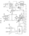
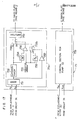
- a hydraulic circuit apparatus generally designated by the reference numeral 8 is constituted to control the driving speeds and directions of actuators by controlling the displacement volumes and delivery directions of hydraulic pumps.
- the hydraulic circuit apparatus 8 comprises first and second variable displacement hydraulic pumps 1 and 10 of the double tilting type, swash plate drive means 2 and 20 for varying the displacement volumes of the pumps 1 and 10, respectively, displacement meters 3 and 30 for sensing the positions of the swash plates of the pumps 1 and 10, respectively, first and second actuators 4 and 40 driven by the pumps 1 and 10, operation levers 5 and 50 for generating signals for instructing the speeds of the actuators 4 and 40, and solenoid-operated on-off valves 6a and 6b for selectively supplying hydraulic fluid from the pump 10.
- the hydraulic pumps 1 and 10 have the same maximum displacement volume.
- the actuator 4 comprises a cylinder unit having a pair of hydraulic cylinders 4a and 4b and having the maximum flow rate requirement which corresponds to the flow rate of fluid delivered by two pumps, and the actuator 40 comprises a single cylinder unit having the maximum flow rate requirement which corresponds to the flow rate of fluid delivered by one pump.
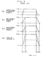
- control unit 7 Prior to description of the control unit 7 according to the invention, the general construction and operation of a control system of the prior art will be outlined by referring to Figs. 2 - 4 to facilitate understanding of the advantages offered by the control unit 7 according to the invention.
- a control unit of the prior art designated by the reference numeral 80 comprises a circuit 81 for judging the order of priority of hydraulic connections between the hydraulic pumps 1 and 10 and the hydraulic cylinders 4 and 40 based on signals from the operation levers 5 and 50, an operational circuit 84 for calculating target tiltings of the swash plates of the hydraulic pumps 1 and 10 based on signals from the operation levers 5 and 50 and a signal from the judging circuit 81, a tilting control circuit 85 for supplying a tilting signal to each of the swash plate drive means 2 and 20 based on signals from the displacement meters 3 and 30 and a signal from the operation circuit 88, a timing circuit 82 for controlling timing of switching of the on-off valves 6a and 6b based on a signal from the judging circuit 81 and a tilting signal from a tilting control circuit 85, and an on-off valve drive circuit 83 for effecting switching of the on-off valves 6a and 6b based on a switch signal from the timing circuit
- the hydraulic pump 1 is exclusively for driving the hydraulic cylinders 4, but the hydraulic pump 10 is preferentially hydraulically connected to the hydraulic cylinder 40, and when the hydraulic cylinder 40 is not driven and the hydraulic cylinders 4 are driven, the hydraulic pump 10 is hydraulically connected to the hydraulic cylinders 4.
- the judging circuit 81 effects control in such a manner that the hydraulic pump 1 takes priority over the hydraulic pump 10 in being hydraulically connected to the hydraulic cylinders 4. In hydraulic excavators and the like, if the hydraulic cylinders 4 and 40 are abruptly driven a force of shock of a high magnitude would be exerted on the body, making it impossible to perform operation.
- a tilting control circuit 73 is provided to effect control of the tilting speed of the swash plates of the hydraulic pumps 1 and 10 in such a manner that predetermined levels are not exceeded by the tilting speeds of the hydraulic pumps 1 and 10 even if the speeds at which the operation levers 5 and 50 are manipulated are high.
- the tilting speed control prevents actual tilting of the swash plates of the hydraulic pumps 1 and 10 from coinciding with the signal from the operation lever 5, so that the displacement volume of the pump 1 is maximized at a time t 2 while the displacement volume of the pump 10 is maximized at a time t 3 .
- acceleration of the hydraulic cylinders 4 from time t 1 to time t 2 becomes twice as high as acceleration of the hydraulic cylinders 4 from time t to time t 1 and from time t 2 to time t 3 .
- the swash plate of the hydraulic pump 10 By returning the operation lever 5 to a neutral position at a time t 4 , the swash plate of the hydraulic pump 10 lower in the order of priority for hydraulic connection to the hydraulic cylinders 4 begans to decrease in tilting to reduce the displacement volume of the pump 10.
- the swash plate of the hydraulic pump 1 At a time t 5 at which the value of a signal from the operation lever 5 becomes 1/2 the maximum value thereof, the swash plate of the hydraulic pump 1 begins to decrease in tilting, and at a time t 6 at which the displacement volume of the pump 10 becomes zero, the on-off valve 6a is closed and the on-off valve 6b is opened.
- the displacement volume of the pump 1 becomes zero.
- deceleration of the hydraulic cylinder 4 from time t 5 to time t 6 becomes twice as high as deceleration of the hydraulic cylinders 4 from time t 4 to time t 5 and from time t 6 to time t 7*
- the acceleration or deceleration of the hydraulic cylinder 4 undergoes changes in this fashion, so that operativity is low and a force of shock of a high magnitude is exerted on the body when the acceleration or deceleration undergoses changes.
- the displacement volume of the hydraulic pump 1 increases and the displacement volume of the hydraulic pump 10 increases after decreasing once.
- the pumps 1 and 10 have a high incidence of changes in the displacement volumes thereof.
- control unit 7 contemplates obviating the aforesaid problems of the prior art to make the acceleration or deceleration of the actuators constant and render the actuator operative as soon as the operation lever is manipulated, as well as to minimize the incidence of changes in the displacement volumes of the pumps.
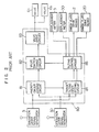
- Fig. 5 shows the entire construction of the control unit 7 of the hydraulic circuit apparatus according to the invention.
- the control unit 7 comprises a judging circuit 71 for judging the order of priority of hydraulic connections between the hydraulic pump 10 and the hydraulic cylinders 4 and 40 and the order of priority of hydraulic connections between the hydraulic cylinders 4 and the hydraulic pumps 1 and 10 based on signals from the operation levers 5 and 50, a swash plate maximum tilting sensing circuit 76 for sensing based on a signal Y 3 from the displacement meter 3 that the absolute value of swash plate tilting of the hydraulic pump 1 has become maximized, a swash plate zero tilting sensing circuit 77 for sensing based on a signal Y 30 from the displacement meter 30 that swash plate tilting of the hydraulic pump 10 is zero, a timing circuit 72 for deciding timing for switching the on-off valves 6a and 6b based on signals from the judging circuit 71 and the zero tilting sensing circuit 77, a drive circuit 73 for effecting switching of the on-
- the hydraulic pump 1 is exclusively for driving the hydraulic cylinders 4, but the hydraulic pump 10 is preferentially hydraulically connected to the hydraulic cylinder 40 and, when the hydraulic cylinder 40 is not driven and the hydraulic cylinders 4 is driven, the hydraulic pump 10 is hydraulically connected to the hydraulic cylinders 4.
- the judging circuit 71 effects control such that the hydraulic pump 1 takes priority over the hydraulic pump 10 for hydraulic connection to the hydraulic cylinders 4.
- the tilting control circuit 75 is provided for controlling tilting speed in such a manner that even if the speeds of manipulation of the operation levers 5 and 50 are high, predetermined levels are not exceeded by swash plate tilting speeds of the hydraulic pumps 1 and 10.
- the operational circuit 74 does operation, when the signal of the operation lever 5 increases, to provide a target tilting for keeping the swash plate tilting of the hydraulic pump 10 at zero until a signal is inputted from the sensing circuit 76 indicating that the swash plate tilting of the pump 10 is maximized, and when the signal of the operation lever 5 decreases, to provide a target tilting for keeping the swash plate tilting of the hydraulic pump 1 at a maximum value until a signal is inputted from the sensing circuit 77 indicating that the swash plate tilting of the pump 10 has become zero.
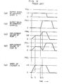
- the control unit 7 When the operation lever 5 is manipulated to generate a signal X 5 at a time t 0 , the circuit 71 judges that the hydraulic pump 1 should take priority over the pump 10 for hydraulic connection to the hydraulic cylinders 4, and the operational circuit 74 does operation to provide a target tilting to increase the swash plate tilting of the pump 1 thereby to increase the displacement volume of the pump 1. If the signal X 5 of the operation lever 5 exceeds one-half the maximum value thereof at a time t IT then the judging circuit 71 judges that the pump 10 should be hydraulically connected to the hydraulic cylinders 4.
- the sensing circuit 76 does not supply a signal because the swash plate tilting of the pump 1 is not maximized yet.
- the operational circuit 74 does operation to provide a target tilting for keeping the swash plate tilting of the pump 10 at zero. If the swash plate tilting of the pump 1 is maximized at a time t 2 , then the sensing circuit 76 supplies a signal and the operational circuit 74 does operation to provide a target tilting for increasing the swash plate tilting of the pump 10.
- the on-off valve 6a is opened and the on-off valve 6b is closed, and thus the displacement volume of the pump 10 begans to increase.
- the swash plate tilting of the pump 10 becomes zero at a time t 5 , then a signal is produced from the sensing circuit 77 and the operational circuit 74 does operation to provide a target tilting for reducing the swash plate tilting of the pump 1.
- the on-off valve 6a is closed and the on-off valve 6b is opened, and thus the displacement volume of the pump 1 begans to decrease. This makes the deceleration of the hydraulic cylinder 4 constant.
- the displacement volume of the pump 1 becomes zero at a time t 6 , and the cylinders 4 are rendered inoperative. If the operation lever 5 is manipulated one-half its maximum amount, then the judging circuit 71 judges that the pump 1 alone should be hydraulically connected to the hydraulic cylinders 4.
- the displacement volume of the pump 1 increases and the speed of the cylinder 4 reaches one-half the maximum speed thereof at a time t 8 . If the operation lever 50 is manipulated at a time t 9 , then the pump 10 is immediately hydraulically connected to the hydraulic cylinder 40 because the displacement volume of the pump 10 is zero at this time.
- Figs. 7 - 16 show the concrete construction of each circuit of the control unit 7.
- the priority order judging circuit 71 of the control unit 7 comprises a window comparator 711 which produces 'o' when the absolute value of a signal X 5 from the operation lever 5 is equal to or below one-half its maximum value and produces '1' when it exceeds the maximum value, and another window comparator 712 which produces '1' in response to a signal X 50 from the operation lever 50 except when it is in the dead zone.
- the output signals of the window comparator 711 and 712 are inputted to a logical circuit 713 comprising a NOT circuit 713a and an AND circuit 713b, and the output signal of the AND circuit 713b is supplied to the valve switch timing circuit 72 and operational circuit 74.
- the relation between a and b inputs and a c output of the logical circuit 713 are as shown in Fig. 8.
- the maximum tilting sensing circuit 76 comprises a comparator 761 for comparing a signal Y 3 from the displacement meter 3 and a reference value V L2 , and producing '1' when V L2 ⁇ Y 3 , and 'o' when V L2 ⁇ Y 3 , a comparator 762 for comparing the signal Y 3 from the displacement meter 3 and a reference value V u2 , and producing '1' when Y 3 ⁇ V u2 , and 'o' when Y 3 ⁇ V u2 , and an OR circuit receiving output signals from the comparators 761 and 762 and supplying an output signal to the operational circuit 74 for calculating target tiltings.
- the circuit 76 constitutes a window comparator which produces 'o' when the signal Y 3 of the displacement meter 3 is positive and smaller than its maximum value and when it is negative and its absolute value is smaller than the absolute value of the maximum negative value and produces '1' when the signal Y 3 of the displacement meter 3 shows the positive and negative maximum values.
- the zero tilting sensing circuit 77 comprises a comparator 771 for comparing a signal Y 30 from the displacement meter 30 and a reference value V L3 , and producing 'I' when V L3 ⁇ Y 30 and producing 'o' when V L3 ⁇ Y 30 , a comparator 772 for comparing the signal Y 30 from the displacement meter 30 and a refer- ence numeral V u3 , and producing '1' when Y 30 ⁇ V u3 and producing 'o' when Y 30 ⁇ V u3 , and an OR circuit 773 receiving output signals of the comparators 771 and 772 and supplying an output signal to the valve switch timing circuit 72 and the target tilting operational circuit 74.
- the circuit 77 constitutes a window comparator producing 'o' when the signal Y 30 of the displacement meter 30 is zero or in the dead zone and producing '1' when the signal Y 30 exceeds the dead zone and its absolute value increases.
- the valve switch timing circuit 72 comprises an OR circuit 722 for inputting the output signal of the juding circuit 71 and the output signal of the zero tilting sensing circuit 77, an OR circuit 723 inputting the output signal of the circuit 71 via a NOT circuit 721 and inputting the output signal of the circuit 77 as it is, and an RS flip-flop circuit 724 inputting the output signals of the OR circuits 722 and 723 at S and R terminals and supplying an output signal from a Q terminal to the valve drive circuit 73 and target tilting operational circuit 74.
- the relation between the S and R inputs and the Q output of the RS flip-flop circuit 724 is as shown in Fig. 14.
- the target tilting operational circuit 74 comprises a first function generator 741a for producing a target tilting signal X c1 for the first pump 1 which signal has its absolute value increase in proportion to an increase in the absolute value of a signal X 5 of the operation lever 5 until the absolute value of the signal X 5 exceeds the dead zone and reaches one-half its maximum value and which signal becomes constant when the absolute value of the signal X 5 reaches one-half its maximum value or become greater than that, and a second function generator 741b for producing a target tilting signal X c2 for the second pump 10 which signal remains zero until the absolute value of the signal X s of the operation lever 5 reaches one-half its maximum value and has its absolute value increase in proportion to an increase in the absolute value of the signal X s as the absolute value of the signal X 5 reaches one-half its maximum value or greater than that.
- a first function generator 741a for producing a target tilting signal X c1 for the first pump 1 which signal has its absolute value increase in proportion to
- a target tilting signal X c1 produced by the first function generator 741a when the signal X 5 of the operation lever 5 is positive and its value has reached one-half its maximum vaule is a signal for commanding a positive maximum swash plate tilting of the hydraulic pump 1
- a target tilting signal X c1 produced thereby when the signal of the operation lever 5 is negative and its value has reached one-half its minimum value is a signal for commanding a negative maximum swash plate tilting of the hydraulic pump 1.
- 742a is a maximum tilting signal generator for producing a target tilting signal X max for commanding a positive maximum swash plate tilting of the first pump 1
- 642b is a minimum tilting signal generator for producing a target tilting signal X min for commanding a minimum or negative maximum swash plate tilting of the first pump 1.
- 743 is a zero tilting signal generator for producing a target tilting signal X o for commanding zero tilting or neutralization of the second pump 10.
- the operational circuit 74 for determining target tilting comprises a third function generator 744 for producing a target tilting signal X c3 for the second pump 10 which has its absolute value increase as the absolute value of a signal X 50 cf the operation lever 50 exceeds the dead zone and increases.
- One of the output signals X c1 , X max and X min of the first function generator 741, maximum tilting signal generator 742a and minimum tilting signal generator 742b is selected by switches 745a and 745b and supplied to a control section 75a for the first pump 1 as a target tilting signal X L1 .
- One of the output signals X c2 , X c3 and X 0 of the second and third function generators 741b and 744 and zero tilting signal generator 743 is selected by switches 745c and 745d and supplied to a control section 75b for the second pump 10 as a target tilting signal X L10 .
- the switches 745a, 745b, 745c and 745d are actuated respectively by a comparator 746, an AND circuit 747, a logical circuit 748 and a NOT circuit 749.
- the comparator 746 produces '1' when a signal Y 3 of the displacement meter 3 is smaller than a reference value V to change the switch 745a to a b terminal side.
- the reference value V o corresponds to the output of the displacement meter 3 when the tilting of the pump 1 is zero.
- the AND circuit 747 produces '1' when the output signals of the valve switch timing circuit 72 and the zero tilting sensing circuit 77 are both '1' to change the switch 745b to the b terminal side.
- the logical circuit 748 comprises an EXOR circuit 748a receiving output signals from the valve switch timing circuit 72 and the judging circuit 71, a NOT circuit 748b receiving an output signal from the EXOR circuit 748a, and an OR circuit 748c receiving output signals from the EXOR circuit 748a and NOT circuit 748b.
- the relation between the inputs and the output of the logical circuit 748 is such that, as shown in Fig. 16, '1' is produced as an output except when inputs are all '1', to change the switch 745c to the b terminal side.
- the NOT circuit 749 produces 'I' when the output signal of the timing circuit 72 is 'o' to change the switch 745d to the b terminal side.
- the comparator 757 performs comparison of the sign of the output ⁇ Y 3 of the adder 751 and produces '1' when ⁇ Y 3 ⁇ 0 to change a switch 758b to an a terminal side and produces 'o' when ⁇ Y 3 ⁇ 0 to change a switch 758b to a b terminal side.
- a reversing circuit 755 reverses the sign of the output a of the generator 753. Thus, if ⁇ Y 3 ⁇ 0, then the output a of the generator 753 is supplied as it is to the switch 758a and if ⁇ Y 3 ⁇ 0, then the output a is supplied to the switch 758a after its sign is reversed.
- dt of the absolute value circuit 754 are compared with each other, and the switch 758a is changed to an a terminal side when ⁇ ⁇ and changed to a b terminal side thereof when a ⁇
- the output selected by the switch 758a is amplified by an amplifier 759 and supplied as its output to the swash plate drive means 2.
- the swash plate tilting speed of the pump 1 is controlled in this fashion so that it may not exceed the set maximum speed a.
- control section 75b for the second pump 10 is of the same construction as the control section 75a for the first pump 1, so that description thereof shall be omitted.
- valve drive circuit 73 comprises an amplifier for amplifying the output signals of the valve switch timing circuit 72.
- control unit 7 of the aforesaid construction Operation of the control unit 7 of the aforesaid construction will be described by referring to the time chart shown in Fig. 6 again.
- the output signal X 5 of the operation lever 5 is one-half or less than one-half of its maximum value and the output signal X 50 of the operation signal X 50 is zero.
- the comparators 711 and 712 both produce 'o' as an output, and the output signal of the logical circuit 713 becomes 'o'.
- the signal Y 30 of the displacement meter 30 is zero, so that the comparators 771 and 772 produce 'o' as an output, and the output of the OR circuit 773 is 'o'.
- valve switch timing circuit 72 the output of the circuit 71 is 'o' and the output of the circuit 77 is 'o', so that the Q terminal output of the RS flip-flop circuit 724 becomes 'o'.
- the on-off valves 6a and 6b are held in closed and open positions, respectively.
- the output of the circuit 72 is 'o' and the output of the circuit 77 is 'o', so that the AND circuit 747 produces 'o' as an output and the switch 745b is located on the a terminal side.
- the NOT circuit 749 produces '1' as an output, so that the switch 745d is located on the b terminal side.
- the signal X 5 of the operation lever 5 is changed into a target tilting signal X cl at the first function generator 741a and the signal X cl is selected by the switch 745b and supplied to the control section 75a for the first pump 1 of the tilting control circuit 75 as a target tilting signal X L1 for the first pump 1.
- the swash plate tilting or the displacement volume of the first pump 1 is controlled in accordance with the target tilting signal X cl .
- control is effected such that the maximum value of the tilting speed is limited to a, so that the displacement volume of the pump 1 is not maximized at time t 1 .
- the output X c3 of the third function generator 747 is selected by the switch 745d, and the swash plate tilting or the displacement volume of the second pump 10 is held at a level zero because the-signal X 50 of the operation lever 50 is zero at this time.
- the signal X 5 of the operation lever 5 exceeds one-half its maximum value, and thus the output of the window comparator 711 becomes '1' in the judging circuit 71. Since the output of the window comparator 712 is 'o', the output of the logical circuit 713 becomes '1'.
- the outputs of the comparators 771 and 772 are both 'o', so that the output of the OR circuit 773 is also 'o'.
- the output of the circuit 71 is '1' and the output of the circuit 77 is 'o', so that the Q terminal output of the RS flip-flop circuit 724 becomes '1'.
- the valves 6a and 6b are changed to open and closed positions respectively.
- the signal Y 3 of the displacement meter 3 does not reach its maximum value yet, so that the comparators 761 and 762 both produce 'o' as an output and the OR circuit 763 also produces 'o'.
- the output of the circuit 72 is '1' and the output of the circuit 77 is 'o', so that the AND circuit produces 'o' as an output and the switch 745b is held on the a terminal side.
- the output of the circuit 71 is '1' and the output of the circuit 72 is 'o', so that the output of the circuit 76 is 'o'.
- the NOT circuit 749 produces 'o' as an output and the switch 745d is changed to the a terminal side.
- the output signal X c1 of the first function generator 711 is produced, and as the target tilting signal X L10 for the second pump 10, the output signal X of the zero tilting signal generator 753 is supplied as an output through the switches 745c and 745d.
- the aforesaid operation is continued up to time t 2 .
- the displacement volume of the first pump 1 is controlled in accordance with the target tilting signal and maximized at time t 2 while having the maximum value of the tilting speed limited to a by the tilting control circuit 75, and the displacement volume of the second pump 10 is kept zero up to time t 2 .
- the displacement volume of the first pump 1 is maximized, and thus the signal Y 3 of the displacement meter 3 indicates a maximum value.
- the output of the comparator 762 becomes '1' and the OR circuit 763 produces '1' as an output.
- the outputs of the circuits 71 and 72 remain '1' and the output of the circuit 77 remains 'o'.
- the AND circuit 747 remains 'o' and the switch 745b is held at the a terminal side, so that the output X c1 of the function generator 741 continues to be produced as a target tilting signal X L1 for the first pump 1.
- the outputs of the circuits 71, 72 and 76 are all '1', so that the logical circuit 748 produces 'o' as an output to change the switch 745c to the a terminal side.
- the switch 745d is held at the a terminal side.
- the signal X 5 of the operation lever 5 is changed by the second function generator 741b to a target tilting signal X c2' which is selected by the switches 745c and 745d and supplied to the control section 75b for the second pump 10 of the tilting control circuit 75 as a target tilting signal X L10 for the second pump 10.
- the displacement volume of the second pump 10 is controlled in accordance with the output X c2 of the second function generator 741b while having the maximum value of the tilting speed limited to a by the circuit 75.
- the second pump 10 begins to increase its displacement volume.
- the signal Y 30 of the displacement meter 30 is not zero and the output of the comparator 772 becomes '1' in the zero tilting sensing circuit 77, so that the OR circuit 773 produces '1' as an output.
- the output of the circuit 77 changes from 'o' to '1', but the Q terminal output of the RS flip-flop circuit 724 is held at '1' in the timing circuit 72.
- the AND circuit 747 produces '1' as an output because its inputs are both '1' to change the switch 745b to the b terminal side.
- the output Y 3 of the displacement meter 3 shows a positive maximum value, so that the comparator 746 produces 'o' to change the switch 745a to the a terminal side.
- the output X max of the maximum tilting signal generator 741a is selected by the switches 745a and 745b and supplied as a target tilting signal X L1 for the first pump 1.
- the outputs of the circuits 71, 72 and 76 are the same as those obtained at time t 2 , so that the output X c2 of the second function generator 741b continues to be produced as a target tilting signal X L10 for the second pump 10.
- the second pump 10 begins to increase its displacement volume, and thereafter the displacement volume of the second pump 10 is controlled in accordance with the target tilting signal X c2 and increases while the maximum value of the tilting speed is limited to a by the circuit 75, and the displacement volume of the first pump 1 is kept at a maximum value.
- the on-off valves 6a and 6b are in open and closed positions, respectively, as aforesaid. Accordingly, the acceleration of the hydraulic cylinder 4 becomes constant as shown in Fig. 6(e).
- the signal X 5 of the operation lever 5 becomes one-half or below on-half its maximum value, so that the outputs of the window comparators 711 and 712 of the judging circuit 71 both become 'o' and the output of the logical circuit 713 also becomes 'o'.
- the output of the circuit 77 remains '1', so that the RS flip-flop circuit 724 continues to produce 'I' as an output.
- the output of the AND circuit 747 and the comparator 746 remains unchanged, so that the output X max of the maximum tilting signal generator 742a continues to be produced as a target tilting signal X L1 for the first pump 1 through the switches 745a and 745b.
- the signal from the circuit 71 which is one of the inputs becomes 'o', so that '1' is produced as an output to change the switch 745c to the b terminal side.
- the switch 745d is held at the a terminal side.
- the output X o of the zero tilting signal generating circuit 743 is selected by the switches 745c and 745d and produced as a target tilting signal X L10 for the second pump 10.
- the displacement volume of the first pump 1 is held at a maximum value and the displacement volume of the second pump 10 is controlled in accordance with the target tilting signal X o and decreases until it becomes zero while having the maximum value of tilting speed limited to a by the circuit 75.
- the displacement volume of the second pump 10 becomes zero, and thus the signal Y 30 of the displacement meter 30 becomes zero and the output of the zero tilting sensing circuit 77 becomes 'o'.
- the output of the judging circuit 71 being also 'o', the output of the timing circuit 72 becomes 'o'.
- the on-off valves 6a and 6b are switched to closed and open positions, respectively.
- the inputs of the AND circuit 747 both become 'o', so that the switch 745b is changed to the a terminal side. Accordingly, the output X cl of the first function generator 741a is selected by the switch 745b and supplied as a target tilting signal X L1 for the first pump 1. Also, the input of the NOT circuit 749 being 'o', it produces '1' as an output to change the switch 745d to the b terminal side. Accordingly, the output X c3 of the third function generator 747 is selected by the switch 745d and supplied as a target tilting signal X L10 for the second pump 10.
- the displacement volume of the first pump 1 is controlled in accordance with the target tilting signal X cl and begins to decrease while having the maximum value of tilting speed limited to a by the circuit 75, and the displacement volume of the second pump 10 is being maintained at zero.
- the signal Y 3 of the displacement meter 3 ceases to be maximum and the output of the maximum tilting sensing circuit 76 becomes 'o'.
- the outputs of the circuits 72 and 77 remain unchanged, so that the switches 745b and 745d remain being held at the a and b terminal sides, respectively. Accordingly, the operation condition prevailing at time t 5 continues.
- the displacement volume of the second pump 10 becomes zero at time t 5
- the displacement volume of the first pump 1 begins to decrease and the displacement volume of the first pump 1 is controlled in accordance with the target tilting signal X c1 and decreases while having the maximum value of tilting speed limited to a by the circuit 75, and the displacement volume of the second pump 10 is being maintained at zero. Accordingly, the deceleration of the hydraulic cylinder 4 becomes constant as shown in Fig. 6(e).
- the signal X 5 of the operation lever 5 is one-half or below one-half its maximum value and the signal X 50 of the operation lever 50 is zero, so that the operation condition of the control unit is the same as the operation condition thereof at the time t o - t l .
- the displacement volume of the first pump 1 is controlled in accordance with the output X c1 of the first function generator 741a and becomes maximum at time t 8 while having the maximum value of tilting speed limited to a by the circuit 75.
- the displacement volume of the second pump 10 is held at zero in accordance with the output X c3 of the third function generator 747.
- the maximum tilting sensing circuit 76 produces '1' as an output.
- the circuits 72 and 77 have 'o' for thier inputs, so that the outputs of the AND circuit 747 and NOT circuit 749 remain unchanged.
- the displacement volume of the first pump 1 is controlled by the output X ci of the first function generator 741a and maintained at a maximum value, as is the case with the displacement volume of the first pump 1 at the time t 7 - t 8 .
- the displacement volume of the second pump 10 is also held at zero. This operation condition continues until time t 9 .
- the signal X 50 of the operation lever 50 ceases to be maximum, so that the output of the window comparator 712 of the judging circuit 71 becomes '1'.
- the output of the window comparator 711 remains 'o', so that the output of the logical circuit 713 remains 'o' also.
- the output of the zero tilting sensing circuit 77 is also 'o', so that the output of the timing circuit 72 also remains 'o'.
- the inputs of the AND circuit 747 and NOT circuit 749 remain unchanged, so that the switches 745b and 745d are on the a and b terminal sides, respectively.
- the displacement volume of the first pump 1 is held at a maximum value by the output of the first function generator 741a, and the displacement volume of the second pump 10 is controlled by the output X c3 of the third function generator 747 and begins to increase while having the maximum value of tilting speed limited to a by the circuit 75.
- the zero tilting sensing circuit 77 produces 'I' as an output.
- the output of the timing circuit 72 remains 'o' because the output of the circuit 71 is 'o'.
- the circuit 747 produces 'o' as an output because the signal of the circuit 72 which is one of its inputs.
- the switch 745a is held at the a terminal side.
- the switch 745d is also held at the b terminal side. Accordingly, the operation condition prevailing at time t 9 continues and the displacement volume of the second pump 10 increases to its maximum value while the displacement volume of the first pump 1 is maintained at a maximum value.
- control unit 7 has been described as being in the form of an operational unit including analogue circuits. However, the control unit 7 may be in the form of a microcomputer.
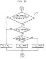
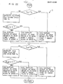
- Figs. 18 - 22 show an embodiment of the invention in which the control unit 7 is in the form of a microcomputer.
- Fig. 18 shows connection of partial flow charts A, B, C and D
- Figs. 19 - 22 show the detailed contents of the partial flow charts A, B, C and D.
- the control unit 7, when constructed in the form of a microcomputer, is capable of operating in the same manner as described by referring to the embodiment in which the control unit 7 is in the form of comprising analogue circuits described hereinabove.
- the actuator is a hydraulic cylinder, but it will be appreciated that the invention can have application in cases where the actuator is a hydraulic motor.
- the hydraulic pumps have been two in number, but it will be also appreciated that one actuator may be connected to three or more actuators.
- swash plate tilting speed has been set constant in controlling the swash plate tilting speed.
- the swash plate tilting speed may be varied depending on the actuator connected to the hydraulic pumps.
- acceleration or deceleration of the actuator is constant, so the apparatus has high operability and is free from shock, and, in the event that the operation lever of another actuator is manipulated while one actuator is being driven for actuation, the actuator begins to operate as soon as the operation lever is manipulated, and also changes in the displacement volume of the hydraulic pump can be minimized in incidence.
Landscapes
- Engineering & Computer Science (AREA)
- General Engineering & Computer Science (AREA)
- Physics & Mathematics (AREA)
- Fluid Mechanics (AREA)
- Mechanical Engineering (AREA)
- Structural Engineering (AREA)
- Mining & Mineral Resources (AREA)
- Civil Engineering (AREA)
- Analytical Chemistry (AREA)
- Chemical & Material Sciences (AREA)
- Fluid-Pressure Circuits (AREA)
- Control Of Positive-Displacement Pumps (AREA)
- Operation Control Of Excavators (AREA)
Applications Claiming Priority (2)
| Application Number | Priority Date | Filing Date | Title |
|---|---|---|---|
| JP56115311A JPS5817202A (ja) | 1981-07-24 | 1981-07-24 | 油圧回路の制御方法 |
| JP115311/81 | 1981-07-24 |
Publications (3)
| Publication Number | Publication Date |
|---|---|
| EP0071228A2 true EP0071228A2 (de) | 1983-02-09 |
| EP0071228A3 EP0071228A3 (en) | 1984-09-05 |
| EP0071228B1 EP0071228B1 (de) | 1987-05-06 |
Family
ID=14659476
Family Applications (1)
| Application Number | Title | Priority Date | Filing Date |
|---|---|---|---|
| EP82106739A Expired EP0071228B1 (de) | 1981-07-24 | 1982-07-26 | Regelsystem für hydraulische Kreislaufvorrichtung |
Country Status (5)
| Country | Link |
|---|---|
| US (1) | US4586330A (de) |
| EP (1) | EP0071228B1 (de) |
| JP (1) | JPS5817202A (de) |
| KR (1) | KR860000756B1 (de) |
| DE (1) | DE3276254D1 (de) |
Cited By (7)
| Publication number | Priority date | Publication date | Assignee | Title |
|---|---|---|---|---|
| EP0104613A2 (de) * | 1982-09-23 | 1984-04-04 | Vickers Incorporated | Kraftübertragung |
| US4586331A (en) * | 1983-05-26 | 1986-05-06 | Caterpillar Industrial Inc. | Automatic hydraulic speed control |
| EP0279356A1 (de) * | 1987-02-19 | 1988-08-24 | Deere & Company | Hydraulisches System für eine Erdbewegungsmaschine |
| EP0301096A1 (de) * | 1987-01-30 | 1989-02-01 | Kabushiki Kaisha Komatsu Seisakusho | Steuerungseinheit |
| EP0665381A1 (de) * | 1994-01-28 | 1995-08-02 | PAUL PLEIGER Maschinenfabrik GmbH & Co. KG | Vorrichtung zum Betreiben von hydraulisch betätigten Armaturen |
| WO1997025532A1 (de) * | 1996-01-10 | 1997-07-17 | Aeroquip-Vickers Internatonal Gmbh | Verlustarmer antrieb für mehrere hydraulische aktuatoren |
| WO2007040837A1 (en) * | 2005-09-30 | 2007-04-12 | Caterpillar Inc. | Multi-pump control system and method |
Families Citing this family (51)
| Publication number | Priority date | Publication date | Assignee | Title |
|---|---|---|---|---|
| CN1010794B (zh) * | 1986-01-11 | 1990-12-12 | 日立建机株式会社 | 液压泵输入功率控制系统 |
| DE3764824D1 (de) * | 1986-01-25 | 1990-10-18 | Hitachi Construction Machinery | Hydraulisches antriebssystem. |
| US4823552A (en) * | 1987-04-29 | 1989-04-25 | Vickers, Incorporated | Failsafe electrohydraulic control system for variable displacement pump |
| US5182908A (en) * | 1992-01-13 | 1993-02-02 | Caterpillar Inc. | Control system for integrating a work attachment to a work vehicle |
| US5365737A (en) * | 1992-08-19 | 1994-11-22 | Komatsu Ltd. | Hydraulically-operated equipment for construction machinery |
| JP3033782U (ja) * | 1996-05-14 | 1997-02-07 | 株式会社トリオパック | 車輌用防暑用具の構造 |
| US5678470A (en) * | 1996-07-19 | 1997-10-21 | Caterpillar Inc. | Tilt priority scheme for a control system |
| JP2000087904A (ja) * | 1998-09-14 | 2000-03-28 | Komatsu Ltd | 圧油供給装置 |
| JP3985756B2 (ja) * | 2003-09-05 | 2007-10-03 | コベルコ建機株式会社 | 建設機械の油圧制御回路 |
| US7121189B2 (en) * | 2004-09-29 | 2006-10-17 | Caterpillar Inc. | Electronically and hydraulically-actuated drain value |
| US7204084B2 (en) * | 2004-10-29 | 2007-04-17 | Caterpillar Inc | Hydraulic system having a pressure compensator |
| US7146808B2 (en) * | 2004-10-29 | 2006-12-12 | Caterpillar Inc | Hydraulic system having priority based flow control |
| US7441404B2 (en) | 2004-11-30 | 2008-10-28 | Caterpillar Inc. | Configurable hydraulic control system |
| US7204185B2 (en) * | 2005-04-29 | 2007-04-17 | Caterpillar Inc | Hydraulic system having a pressure compensator |
| US7243493B2 (en) * | 2005-04-29 | 2007-07-17 | Caterpillar Inc | Valve gradually communicating a pressure signal |
| US7194856B2 (en) * | 2005-05-31 | 2007-03-27 | Caterpillar Inc | Hydraulic system having IMV ride control configuration |
| US7302797B2 (en) * | 2005-05-31 | 2007-12-04 | Caterpillar Inc. | Hydraulic system having a post-pressure compensator |
| US7210396B2 (en) * | 2005-08-31 | 2007-05-01 | Caterpillar Inc | Valve having a hysteretic filtered actuation command |
| US7331175B2 (en) * | 2005-08-31 | 2008-02-19 | Caterpillar Inc. | Hydraulic system having area controlled bypass |
| US20100043418A1 (en) * | 2005-09-30 | 2010-02-25 | Caterpillar Inc. | Hydraulic system and method for control |
| US7614336B2 (en) * | 2005-09-30 | 2009-11-10 | Caterpillar Inc. | Hydraulic system having augmented pressure compensation |
| US7320216B2 (en) * | 2005-10-31 | 2008-01-22 | Caterpillar Inc. | Hydraulic system having pressure compensated bypass |
| JP4230494B2 (ja) * | 2006-06-06 | 2009-02-25 | 日立建機株式会社 | 電気駆動ダンプトラックの駆動システム |
| US20080295681A1 (en) * | 2007-05-31 | 2008-12-04 | Caterpillar Inc. | Hydraulic system having an external pressure compensator |
| US7621211B2 (en) * | 2007-05-31 | 2009-11-24 | Caterpillar Inc. | Force feedback poppet valve having an integrated pressure compensator |
| US8479504B2 (en) * | 2007-05-31 | 2013-07-09 | Caterpillar Inc. | Hydraulic system having an external pressure compensator |
| JP5027705B2 (ja) * | 2008-03-25 | 2012-09-19 | 株式会社小松製作所 | 作動油供給装置および建設機械 |
| US8631650B2 (en) | 2009-09-25 | 2014-01-21 | Caterpillar Inc. | Hydraulic system and method for control |
| KR20120072729A (ko) * | 2010-12-24 | 2012-07-04 | 두산인프라코어 주식회사 | 상이한 컷오프 압력을 구비한 유압 펌프를 포함하는 휠로더 |
| US8966892B2 (en) | 2011-08-31 | 2015-03-03 | Caterpillar Inc. | Meterless hydraulic system having restricted primary makeup |
| US8863509B2 (en) | 2011-08-31 | 2014-10-21 | Caterpillar Inc. | Meterless hydraulic system having load-holding bypass |
| US8944103B2 (en) | 2011-08-31 | 2015-02-03 | Caterpillar Inc. | Meterless hydraulic system having displacement control valve |
| US9151018B2 (en) | 2011-09-30 | 2015-10-06 | Caterpillar Inc. | Closed-loop hydraulic system having energy recovery |
| US9051714B2 (en) * | 2011-09-30 | 2015-06-09 | Caterpillar Inc. | Meterless hydraulic system having multi-actuator circuit |
| US8966891B2 (en) | 2011-09-30 | 2015-03-03 | Caterpillar Inc. | Meterless hydraulic system having pump protection |
| US9057389B2 (en) | 2011-09-30 | 2015-06-16 | Caterpillar Inc. | Meterless hydraulic system having multi-actuator circuit |
| US8910474B2 (en) | 2011-10-21 | 2014-12-16 | Caterpillar Inc. | Hydraulic system |
| US8984873B2 (en) | 2011-10-21 | 2015-03-24 | Caterpillar Inc. | Meterless hydraulic system having flow sharing and combining functionality |
| US8919114B2 (en) | 2011-10-21 | 2014-12-30 | Caterpillar Inc. | Closed-loop hydraulic system having priority-based sharing |
| US8978373B2 (en) | 2011-10-21 | 2015-03-17 | Caterpillar Inc. | Meterless hydraulic system having flow sharing and combining functionality |
| US8893490B2 (en) | 2011-10-21 | 2014-11-25 | Caterpillar Inc. | Hydraulic system |
| US8943819B2 (en) | 2011-10-21 | 2015-02-03 | Caterpillar Inc. | Hydraulic system |
| US8973358B2 (en) | 2011-10-21 | 2015-03-10 | Caterpillar Inc. | Closed-loop hydraulic system having force modulation |
| US8978374B2 (en) | 2011-10-21 | 2015-03-17 | Caterpillar Inc. | Meterless hydraulic system having flow sharing and combining functionality |
| US9068578B2 (en) | 2011-10-21 | 2015-06-30 | Caterpillar Inc. | Hydraulic system having flow combining capabilities |
| US9080310B2 (en) | 2011-10-21 | 2015-07-14 | Caterpillar Inc. | Closed-loop hydraulic system having regeneration configuration |
| US9279236B2 (en) | 2012-06-04 | 2016-03-08 | Caterpillar Inc. | Electro-hydraulic system for recovering and reusing potential energy |
| US9290912B2 (en) | 2012-10-31 | 2016-03-22 | Caterpillar Inc. | Energy recovery system having integrated boom/swing circuits |
| US9290911B2 (en) | 2013-02-19 | 2016-03-22 | Caterpillar Inc. | Energy recovery system for hydraulic machine |
| US10119556B2 (en) * | 2015-12-07 | 2018-11-06 | Caterpillar Inc. | System having combinable transmission and implement circuits |
| JP6510396B2 (ja) * | 2015-12-28 | 2019-05-08 | 日立建機株式会社 | 作業機械 |
Citations (3)
| Publication number | Priority date | Publication date | Assignee | Title |
|---|---|---|---|---|
| US3754394A (en) * | 1971-12-02 | 1973-08-28 | Hyster Co | Hydraulic control system for electric lift truck |
| US3922855A (en) * | 1971-12-13 | 1975-12-02 | Caterpillar Tractor Co | Hydraulic circuitry for an excavator |
| GB2045360A (en) * | 1979-02-26 | 1980-10-29 | Hitachi Construction Machinery | Drive system for construction machinery |
Family Cites Families (5)
| Publication number | Priority date | Publication date | Assignee | Title |
|---|---|---|---|---|
| US3060858A (en) * | 1955-11-24 | 1962-10-30 | Shoosmith Guy Taite | Pump installation |
| US4113054A (en) * | 1977-04-01 | 1978-09-12 | Mobile Aerial Towers, Inc. | Fluid control system for mobile aerial towers |
| US4369625A (en) * | 1979-06-27 | 1983-01-25 | Hitachi Construction Machinery Co., Ltd. | Drive system for construction machinery and method of controlling hydraulic circuit means thereof |
| GB2072890B (en) * | 1979-10-15 | 1983-08-10 | Hitachi Construction Machinery | Method of controlling internal combustion engine and hydraulic pump system |
| US4399653A (en) * | 1980-03-14 | 1983-08-23 | Pylat Jr John A | Automatic adjusting deceleration control for a hydrostatically powered device |
-
1981
- 1981-07-24 JP JP56115311A patent/JPS5817202A/ja active Granted
-
1982
- 1982-07-23 US US06/401,304 patent/US4586330A/en not_active Expired - Fee Related
- 1982-07-24 KR KR8203322A patent/KR860000756B1/ko active
- 1982-07-26 EP EP82106739A patent/EP0071228B1/de not_active Expired
- 1982-07-26 DE DE8282106739T patent/DE3276254D1/de not_active Expired
Patent Citations (3)
| Publication number | Priority date | Publication date | Assignee | Title |
|---|---|---|---|---|
| US3754394A (en) * | 1971-12-02 | 1973-08-28 | Hyster Co | Hydraulic control system for electric lift truck |
| US3922855A (en) * | 1971-12-13 | 1975-12-02 | Caterpillar Tractor Co | Hydraulic circuitry for an excavator |
| GB2045360A (en) * | 1979-02-26 | 1980-10-29 | Hitachi Construction Machinery | Drive system for construction machinery |
Cited By (14)
| Publication number | Priority date | Publication date | Assignee | Title |
|---|---|---|---|---|
| EP0104613A3 (en) * | 1982-09-23 | 1985-06-26 | Vickers, Incorporated | Power transmission |
| EP0104613A2 (de) * | 1982-09-23 | 1984-04-04 | Vickers Incorporated | Kraftübertragung |
| US4586331A (en) * | 1983-05-26 | 1986-05-06 | Caterpillar Industrial Inc. | Automatic hydraulic speed control |
| US5029067A (en) * | 1987-01-30 | 1991-07-02 | Kabushiki Kaisha Komatsu Seisakusho | Operation control device |
| EP0301096A1 (de) * | 1987-01-30 | 1989-02-01 | Kabushiki Kaisha Komatsu Seisakusho | Steuerungseinheit |
| EP0301096A4 (de) * | 1987-01-30 | 1989-10-12 | Komatsu Mfg Co Ltd | Steuerungseinheit. |
| EP0279356A1 (de) * | 1987-02-19 | 1988-08-24 | Deere & Company | Hydraulisches System für eine Erdbewegungsmaschine |
| EP0665381A1 (de) * | 1994-01-28 | 1995-08-02 | PAUL PLEIGER Maschinenfabrik GmbH & Co. KG | Vorrichtung zum Betreiben von hydraulisch betätigten Armaturen |
| CN1090297C (zh) * | 1994-01-28 | 2002-09-04 | 保罗·普莱格机械制造责任两合公司 | 操纵液压附件的装置 |
| WO1997025532A1 (de) * | 1996-01-10 | 1997-07-17 | Aeroquip-Vickers Internatonal Gmbh | Verlustarmer antrieb für mehrere hydraulische aktuatoren |
| US6205780B1 (en) | 1996-01-10 | 2001-03-27 | Aeroquip-Vickers International Gmbh | Low-loss drive system for a plurality of hydraulic actuators |
| WO2007040837A1 (en) * | 2005-09-30 | 2007-04-12 | Caterpillar Inc. | Multi-pump control system and method |
| US7412827B2 (en) | 2005-09-30 | 2008-08-19 | Caterpillar Inc. | Multi-pump control system and method |
| JP2009510359A (ja) * | 2005-09-30 | 2009-03-12 | キャタピラー インコーポレイテッド | 多数のポンプ用の制御システムおよび制御方法 |
Also Published As
| Publication number | Publication date |
|---|---|
| KR860000756B1 (ko) | 1986-06-18 |
| DE3276254D1 (en) | 1987-06-11 |
| KR840000747A (ko) | 1984-02-27 |
| JPS6342122B2 (de) | 1988-08-22 |
| EP0071228A3 (en) | 1984-09-05 |
| US4586330A (en) | 1986-05-06 |
| EP0071228B1 (de) | 1987-05-06 |
| JPS5817202A (ja) | 1983-02-01 |
Similar Documents
| Publication | Publication Date | Title |
|---|---|---|
| EP0071228A2 (de) | Regelsystem für hydraulische Kreislaufvorrichtung | |
| US4510750A (en) | Circuit pressure control system for hydrostatic power transmission | |
| US4369625A (en) | Drive system for construction machinery and method of controlling hydraulic circuit means thereof | |
| EP0522171B1 (de) | Hydraulisches steuerungssystem für hydraulische erdbaumaschine | |
| US5085051A (en) | Displacement of variable displacement pump controlled by load sensing device having two settings for low and high speed operation of an actuator | |
| EP0362402B1 (de) | Verfahren und vorrichtung zum antrieb einer hydraulischen vorrichtung | |
| EP0695875A1 (de) | Hydraulischer pumpenregler | |
| EP0045664B1 (de) | Druckregeleinrichtung für ein hydrostatisches Getriebe | |
| EP0376295A1 (de) | Hydraulische Steuerregelungsvorrichtung für Baumaschinen | |
| EP0783057A1 (de) | Hydraulisches Betätigungssystem für Baumaschinen | |
| JPS6319724B2 (de) | ||
| JP2657548B2 (ja) | 油圧駆動装置及びその制御方法 | |
| JPH08209751A (ja) | 油圧流優先システム | |
| JPS6261742B2 (de) | ||
| JP3535667B2 (ja) | 建設機械の油圧駆動装置 | |
| US5810046A (en) | Device and method for selecting control mode in power construction vehicle | |
| GB2045360A (en) | Drive system for construction machinery | |
| JPH08219107A (ja) | 油圧機械の油圧再生装置 | |
| JPS58204940A (ja) | エンジンの燃料噴射ポンプ制御装置 | |
| US20020104431A1 (en) | Method and apparatus for controlling the actuation of a hydraulic cylinder | |
| KR920008658Y1 (ko) | 굴삭기의 유압제어장치 | |
| JP2871871B2 (ja) | 建設機械の油圧駆動装置 | |
| KR940000247B1 (ko) | 굴삭기 스윙모우터와 부움실린더의 상대속도 제어방법 | |
| JPH0641762B2 (ja) | 油圧回路の駆動制御装置 | |
| JP3395400B2 (ja) | クレーン作業機械の油圧回路 |
Legal Events
| Date | Code | Title | Description |
|---|---|---|---|
| PUAI | Public reference made under article 153(3) epc to a published international application that has entered the european phase |
Free format text: ORIGINAL CODE: 0009012 |
|
| AK | Designated contracting states |
Designated state(s): DE FR |
|
| PUAL | Search report despatched |
Free format text: ORIGINAL CODE: 0009013 |
|
| AK | Designated contracting states |
Designated state(s): DE FR |
|
| 17P | Request for examination filed |
Effective date: 19850201 |
|
| 17Q | First examination report despatched |
Effective date: 19860128 |
|
| GRAA | (expected) grant |
Free format text: ORIGINAL CODE: 0009210 |
|
| AK | Designated contracting states |
Kind code of ref document: B1 Designated state(s): DE FR |
|
| ET | Fr: translation filed | ||
| REF | Corresponds to: |
Ref document number: 3276254 Country of ref document: DE Date of ref document: 19870611 |
|
| PLBE | No opposition filed within time limit |
Free format text: ORIGINAL CODE: 0009261 |
|
| STAA | Information on the status of an ep patent application or granted ep patent |
Free format text: STATUS: NO OPPOSITION FILED WITHIN TIME LIMIT |
|
| 26N | No opposition filed | ||
| PGFP | Annual fee paid to national office [announced via postgrant information from national office to epo] |
Ref country code: FR Payment date: 19940520 Year of fee payment: 13 |
|
| PGFP | Annual fee paid to national office [announced via postgrant information from national office to epo] |
Ref country code: DE Payment date: 19940930 Year of fee payment: 13 |
|
| PG25 | Lapsed in a contracting state [announced via postgrant information from national office to epo] |
Ref country code: DE Effective date: 19960402 |
|
| PG25 | Lapsed in a contracting state [announced via postgrant information from national office to epo] |
Ref country code: FR Effective date: 19960430 |
|
| REG | Reference to a national code |
Ref country code: FR Ref legal event code: ST |
|
| REG | Reference to a national code |
Ref country code: FR Ref legal event code: ST |
|
| REG | Reference to a national code |
Ref country code: FR Ref legal event code: ST |