EP0071007B1 - Capteur de vitesse angulaire utilisant un laser - Google Patents
Capteur de vitesse angulaire utilisant un laser Download PDFInfo
- Publication number
- EP0071007B1 EP0071007B1 EP82105087A EP82105087A EP0071007B1 EP 0071007 B1 EP0071007 B1 EP 0071007B1 EP 82105087 A EP82105087 A EP 82105087A EP 82105087 A EP82105087 A EP 82105087A EP 0071007 B1 EP0071007 B1 EP 0071007B1
- Authority
- EP
- European Patent Office
- Prior art keywords
- layer
- prism
- magneto
- refractive index
- angular velocity
- Prior art date
- Legal status (The legal status is an assumption and is not a legal conclusion. Google has not performed a legal analysis and makes no representation as to the accuracy of the status listed.)
- Expired
Links
- 239000000463 material Substances 0.000 claims description 38
- 230000000694 effects Effects 0.000 claims description 20
- 239000003989 dielectric material Substances 0.000 claims description 11
- 238000002310 reflectometry Methods 0.000 claims description 6
- 230000035515 penetration Effects 0.000 claims description 3
- 230000005374 Kerr effect Effects 0.000 claims 11
- 230000002238 attenuated effect Effects 0.000 claims 3
- 230000005291 magnetic effect Effects 0.000 description 7
- 239000002223 garnet Substances 0.000 description 5
- 230000001902 propagating effect Effects 0.000 description 5
- 238000010521 absorption reaction Methods 0.000 description 3
- 239000011521 glass Substances 0.000 description 3
- 230000005415 magnetization Effects 0.000 description 3
- 229910052751 metal Inorganic materials 0.000 description 3
- 239000002184 metal Substances 0.000 description 3
- 230000003287 optical effect Effects 0.000 description 3
- 239000000126 substance Substances 0.000 description 3
- 238000005102 attenuated total reflection Methods 0.000 description 2
- 230000008878 coupling Effects 0.000 description 2
- 238000010168 coupling process Methods 0.000 description 2
- 238000005859 coupling reaction Methods 0.000 description 2
- 230000001419 dependent effect Effects 0.000 description 2
- 230000005294 ferromagnetic effect Effects 0.000 description 2
- 239000003302 ferromagnetic material Substances 0.000 description 2
- 230000010363 phase shift Effects 0.000 description 2
- 230000010287 polarization Effects 0.000 description 2
- 230000003014 reinforcing effect Effects 0.000 description 2
- 229910000679 solder Inorganic materials 0.000 description 2
- VEALVRVVWBQVSL-UHFFFAOYSA-N strontium titanate Chemical compound [Sr+2].[O-][Ti]([O-])=O VEALVRVVWBQVSL-UHFFFAOYSA-N 0.000 description 2
- ZOXJGFHDIHLPTG-UHFFFAOYSA-N Boron Chemical compound [B] ZOXJGFHDIHLPTG-UHFFFAOYSA-N 0.000 description 1
- MCMNRKCIXSYSNV-UHFFFAOYSA-N ZrO2 Inorganic materials O=[Zr]=O MCMNRKCIXSYSNV-UHFFFAOYSA-N 0.000 description 1
- 239000003570 air Substances 0.000 description 1
- 239000012080 ambient air Substances 0.000 description 1
- 239000006117 anti-reflective coating Substances 0.000 description 1
- 230000003667 anti-reflective effect Effects 0.000 description 1
- 230000002146 bilateral effect Effects 0.000 description 1
- 229910052796 boron Inorganic materials 0.000 description 1
- 238000010276 construction Methods 0.000 description 1
- 229910001610 cryolite Inorganic materials 0.000 description 1
- 230000007423 decrease Effects 0.000 description 1
- 230000005670 electromagnetic radiation Effects 0.000 description 1
- 238000004519 manufacturing process Methods 0.000 description 1
- RVTZCBVAJQQJTK-UHFFFAOYSA-N oxygen(2-);zirconium(4+) Chemical compound [O-2].[O-2].[Zr+4] RVTZCBVAJQQJTK-UHFFFAOYSA-N 0.000 description 1
- 230000000149 penetrating effect Effects 0.000 description 1
- 230000000737 periodic effect Effects 0.000 description 1
- 239000010453 quartz Substances 0.000 description 1
- 230000005855 radiation Effects 0.000 description 1
- VYPSYNLAJGMNEJ-UHFFFAOYSA-N silicon dioxide Inorganic materials O=[Si]=O VYPSYNLAJGMNEJ-UHFFFAOYSA-N 0.000 description 1
- 239000007787 solid Substances 0.000 description 1
Images

Classifications
-
- G—PHYSICS
- G01—MEASURING; TESTING
- G01C—MEASURING DISTANCES, LEVELS OR BEARINGS; SURVEYING; NAVIGATION; GYROSCOPIC INSTRUMENTS; PHOTOGRAMMETRY OR VIDEOGRAMMETRY
- G01C19/00—Gyroscopes; Turn-sensitive devices using vibrating masses; Turn-sensitive devices without moving masses; Measuring angular rate using gyroscopic effects
- G01C19/58—Turn-sensitive devices without moving masses
- G01C19/64—Gyrometers using the Sagnac effect, i.e. rotation-induced shifts between counter-rotating electromagnetic beams
- G01C19/66—Ring laser gyrometers
- G01C19/68—Lock-in prevention
Definitions
- the invention relates to a laser speedometer according to the preamble of claim 1.
- inertial rotational speeds can be measured with laser rotational speed meters by determining the frequency difference between the electromagnetic waves propagating in opposite directions. It is also known that at input rotational speeds that fall below a certain threshold value, this frequency difference disappears and the rotational speed meter loses its ability to measure small rotational speeds. This phenomenon is known as the lock-in effect.
- Various measures have been developed to circumvent the lock-in effect, all of which are based in principle on forcing the ring laser to split zero-frequency, or - in other words - moving its operating point outside the lock-in band.
- the magneto-optical core effect is the application of the magneto-optical core effect.
- the light is reflected at the interface between two media, at least one of which is gyrotropic, i.e. must have the magneto-optical core effect, a non-reciprocal (i.e. direction-dependent) phase shift is imposed.
- Such a magnetic mirror must have not only a sufficient distortion effect but also a sufficiently high reflectivity to be able to serve as a resonator mirror. These two requirements prevent the use of pure metal mirrors made of ferromagnetic material, since they have a sufficient distortion effect, but they do not have sufficient reflectivity for the application mentioned (typical reflection values are between 40 and 70%). To remedy this, US-A-4,225,239 teaches how to increase the reflectivity of the pure metal surface by applying dielectric layers. However, this not insignificantly reduces the distortion effect of such a mirror, since due to the reflection in the dielectric layers, only a fraction of the incident electromagnetic wave reaches the magnetized layer. The in DE-A-2432479 and others.
- a Kerr mirror consisting of an alternating sequence of quarter-wavelength layers of a dielectric and a ferromagnetic material has proven to be difficult to implement technically.
- DE-A-2 919 590 teaches to arrange a gyrotropic garnet layer in front of a dielectric layer system.
- a plate made of a non-magnetized garnet material is required, on the side of which is remote from the beam, the gyrotropic layer and the subsequent dielectric layers are suitably applied. Therefore, despite the anti-reflective coating on the beam-facing side, reflection losses cannot be avoided, as well as absorption losses in the garnet material itself.
- dielectric layer systems with a high degree of reflection for p-polarized light as is used, for example, in the magneto-optical core effect with a transverse direction of the magnetic field (magnetic field vector perpendicular to the beam incidence plane), is more difficult than for, for example, s-polarized light.
- the object on which the invention is based is to create a laser rotational speed meter with an element which, using the magneto-optical core effect, produces the largest possible phase jump difference and consequently the greatest possible frequency splitting of the oppositely rotating electromagnetic waves and a high reflectivity for has the laser radiation used.
- the solution according to the invention also has the advantage that the desired state of polarization of the electromagnetic waves is maintained without further aids and that it is simple to produce.
- the prism itself or the adjacent layer of gyrotropic d. H. the material causing the magneto-optical core effect or both materials can also be gyrotropic; The magnetic field acts on this material, which leads to the magneto-optical core effect.
- the reflector used in the invention is used as a corner reflector in a triangular or square circulation path and not as an additional reflector.
- the use of prisms instead of mirrors as reflectors is known per se (US-A-3 545 866). It is essential for the invention, however, that such a prism is incorporated into a magneto-optical element, using the effect of the attenuated total reflection.
- the layer which is located at the base interface of the prism is made of gyrotropic material
- the requirement to use a gyrotropic material which has a refractive index which is substantially smaller than that of the prism is a limitation of the number of substances which can be used, since the most gyrotropic substances generally have a high refractive index. This makes it at least difficult to find a substance that also has the largest possible Faraday rotation and the lowest possible absorption.
- Embodiments of the invention are therefore based on the object of developing the proposed solution in such a way that the requirement for a specific refractive index of the gyrotropic material loses its meaning and the gyrotropic material can therefore be selected primarily with regard to the other requirements.
- the layer adjoining the base interface of the prism being formed as a multiple layer.
- the total reflection takes place at the interface between the gyrotropic sublayer and the dielectric sublayer, the light penetrating the gyrotropic material, which is now very little absorbing, and can thus be influenced in phase by means of the magnetic field.
- the second sub-layer can also be air or vacuum.
- the prism borders on a dielectric sublayer with a lower refractive index.
- the second partial layer of the magneto-optical kerf effect is applied to this, into which, with a suitably selected thickness of the first partial layer, a sufficient proportion of the transversely damped wave which arises during total reflection at the interface between the prism and the first partial layer can still enter.
- the desired phase influence is then achieved with suitable magnetization of the gyrotropic partial layer.
- the gyrotropic partial layer should be thicker than the penetration depth of the transverse damped wave propagating in it. This penetration depth is about one to two wavelengths of the light used.
- the thickness of the gyrotropic partial layer must be optimized so that a maximum phase jump difference is achieved.
- a further increase in the phase jump difference can be achieved by connecting a third partial layer made of dielectric material to the gyrotropic partial layer.
- the 1 consists of an optical amplifier 1, a mirror 2, a partially transparent mirror 3, another mirror 4, a beam splitter 4a, the reflector 5 and a detector 7 for measuring the frequency difference of the waves.
- the oppositely rotating laser beams are designated 8 and 9.
- the reflectors 2, 3 and 5 are designed and arranged such that the circulation paths shown come about.
- the beam 9 is reflected on the mirror 2, partially reflected by the mirror 3 and the remaining portion is returned from the reflector 5 to the optical amplifier 1.
- the part let through the mirror 3 reaches the detector 7.
- the beam 8 is deflected in the reflector 5, partly deflected from the partially transparent mirror 3 to the mirror 2 and from there returned to the optical amplifier.
- the part that is let through by the partially transparent mirror is directed by the mirror 4 onto the beam splitter 4a and a part thereof is also deflected to the detector 7.
- the reflector 5 is constructed in a special way to suppress the lock-in effect. It consists of a prism 5a (eg made of strontium titanate) of a certain refractive index n 1 ; whose side surfaces 5b are inclined so that due to the fulfillment of the Brewster condition there is no reflection of the p-polarized rays (8 or 9) that occur. On the base surface 5d of the prism is a layer 5c of a gyrotropic material z. B. applied from ferromagnetic garnet material; this material has a refractive index n 2 which is smaller than the aperture in the prism 5a. This occurs at the boundary layer 5d between prism 5a and layer 5c an attenuated total reflection of the rays.
- a prism 5a eg made of strontium titanate
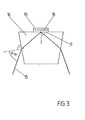
- a differently designed reflector which can replace the reflector 5 of Fig. 1, is shown. It consists of the coupling prism 11 made of dielectric material (refractive index n,) and with the angle ⁇ , the gyrotropic layer 12 (refractive index n 2 ) applied thereon and an additional dielectric layer 13 (refractive index n 3 ).
- the laser beams 14 are incident on the side surfaces of the coupling prism 11 (for example made of glass) at the Brewster angle a Br and are refracted towards the solder due to the greater density (n 1 ) of the prism material. They hit the layer 12 (for example made of ferromagnetic garnet material) at the angle a 1 , and since the refractive index (n 2 ) of the gyrotropic material is greater here, they are broken back to the solder. Then they hit the layer 13 at an angle a 2 , and since the material (eg cryolite, Mg F 2 ) of this dielectric layer has a significantly smaller refractive index (n 3 ) (eg close to 1.0), it occurs the interface of layers 12/13 total reflection.
- the magnetization of the layer 12 creates a non-reciprocal phase influence on the waves propagating in opposite directions and thus the desired phase jump difference.
- the layer 13 can also be the ambient air or the ambient vacuum, for which the condition of refractive index close to 1 or 1 applies.
- a pronounced layer of a solid dielectric material is also conceivable.
- the thickness of the layer 12 of the gyrotropic material is to be selected such that the distortion effects leading to the phase jump difference are mutually reinforcing in the reflections at the upper and lower interface of the gyrotropic layer 12.
- the absorption losses of the reflector 5 increase monotonically with the thickness d 2 of the layer 12, and the phase jump difference achieved in the thickness of the layer 12 is periodic.
- the light beam 15 enters the prism 16 at the Brewster angle UBr to avoid reflection losses, which prism 16 is made of commercially available glasses with a suitable refractive index, such as, for example, heavy-flint boron glass, strontium titanate, zirconium dioxide, quartz or the like. consists.
- the entrance surfaces of the prism can also be anti-reflective.
- the beam strikes the interface 17 to the dielectric layer 18, where it is totally reflected at a sufficiently low refractive index of the material of the layer 18 and deflected by the desired angle.
- the cross-damped wave occurring during total reflection propagates along the interface 17.
- the layer 18 decreases exponentially with the distance from the interface 17, but, with a suitably small thickness of the layer 18 (order of magnitude 10 nm), it still extends into the gyrotropic partial layer 19.
- the thickness of the gyrotropic sublayer 19 must be chosen as a function of the ratio of its refractive index to the aperture in the prism. With a suitable magnetization of the medium 19, the desired phase jump difference arises through a non-reciprocal phase influencing of the waves propagating in opposite directions.
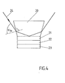
- the exemplary embodiment in FIG. 4 contains 3 sublayers.
- the light beam 24 also enters the prism 20 here again at the Brewster angle ⁇ Br .
- the refractive index of the dielectric layer adjoining the prism base is chosen to be so small that total reflection occurs at the interface between prism 20 and dielectric sublayer 21.
- a further dielectric sublayer 23 follows the gyrotropic sublayer 22.
- the structure of the layers 21, 22, 23 is chosen with regard to its thickness and refractive index so that the distortion effects occurring due to the magnetic field occur in the reflections at the upper and lower boundary surfaces of the gyrotropic layer reinforce each other.
Landscapes
- Physics & Mathematics (AREA)
- Engineering & Computer Science (AREA)
- Optics & Photonics (AREA)
- Electromagnetism (AREA)
- Power Engineering (AREA)
- General Physics & Mathematics (AREA)
- Radar, Positioning & Navigation (AREA)
- Remote Sensing (AREA)
- Gyroscopes (AREA)
- Lasers (AREA)
Claims (9)
caractérisé en ce que
Applications Claiming Priority (4)
| Application Number | Priority Date | Filing Date | Title |
|---|---|---|---|
| DE3123518 | 1981-06-13 | ||
| DE19813123518 DE3123518A1 (de) | 1981-06-13 | 1981-06-13 | Laser-drehgeschwindigkeitsmesser |
| DE3145703 | 1981-11-19 | ||
| DE3145703 | 1981-11-19 |
Publications (2)
| Publication Number | Publication Date |
|---|---|
| EP0071007A1 EP0071007A1 (fr) | 1983-02-09 |
| EP0071007B1 true EP0071007B1 (fr) | 1986-10-08 |
Family
ID=25793878
Family Applications (1)
| Application Number | Title | Priority Date | Filing Date |
|---|---|---|---|
| EP82105087A Expired EP0071007B1 (fr) | 1981-06-13 | 1982-06-10 | Capteur de vitesse angulaire utilisant un laser |
Country Status (3)
| Country | Link |
|---|---|
| EP (1) | EP0071007B1 (fr) |
| JP (1) | JPS58500913A (fr) |
| WO (1) | WO1982004483A1 (fr) |
Families Citing this family (1)
| Publication number | Priority date | Publication date | Assignee | Title |
|---|---|---|---|---|
| US9348000B1 (en) | 2012-12-20 | 2016-05-24 | Seagate Technology Llc | Magneto optic kerr effect magnetometer for ultra-high anisotropy magnetic measurements |
Family Cites Families (7)
| Publication number | Priority date | Publication date | Assignee | Title |
|---|---|---|---|---|
| US3545866A (en) * | 1967-06-15 | 1970-12-08 | Hubert C Swanson | Ring laser which utilizes only one of the counterrotating beams to determine rotation rate |
| US3752586A (en) * | 1969-08-04 | 1973-08-14 | North American Rockwell | Minimizing frequency locking in ring laser gyroscopes |
| US3851973A (en) * | 1972-01-03 | 1974-12-03 | Sperry Rand Corp | Ring laser magnetic bias mirror compensated for non-reciprocal loss |
| DE2432479C2 (de) * | 1974-07-04 | 1985-05-30 | Sperry Corp., New York, N.Y. | Ringlaser |
| US4195908A (en) * | 1978-05-15 | 1980-04-01 | Sperry Corporation | Magnetic mirror for imparting non-reciprocal phase shift |
| US4225239A (en) * | 1979-07-05 | 1980-09-30 | The United States Of America As Represented By The Secretary Of The Navy | Magneto-optic bias of ring laser using reflective magneto-optic element at near-grazing incidence |
| DE3115906A1 (de) * | 1981-04-21 | 1982-10-28 | Deutsche Forschungs- und Versuchsanstalt für Luft- und Raumfahrt e.V., 5000 Köln | Ringlaser |
-
1982
- 1982-06-10 JP JP57501883A patent/JPS58500913A/ja active Pending
- 1982-06-10 EP EP82105087A patent/EP0071007B1/fr not_active Expired
- 1982-06-10 WO PCT/EP1982/000122 patent/WO1982004483A1/fr not_active Ceased
Also Published As
| Publication number | Publication date |
|---|---|
| WO1982004483A1 (fr) | 1982-12-23 |
| EP0071007A1 (fr) | 1983-02-09 |
| JPS58500913A (ja) | 1983-06-02 |
Similar Documents
| Publication | Publication Date | Title |
|---|---|---|
| EP0087101B1 (fr) | Prisme polariseur optique sans réflexion | |
| DE2418994C2 (de) | Wellenleiterstruktur mit Dünnschichtfilter und Verfahren zu deren Herstellung | |
| DE3879593T2 (de) | Optische bildumkehrsysteme. | |
| DE60021689T2 (de) | Multifunktioneller integriert-optischer Chip mit verbessertem Polarisationsauslöschungsverhältnis | |
| CH661154A5 (de) | Verfahren und vorrichtung zur unterdrueckung unerwuenschter resonanzschwingungszustaende in einem ringlaser-drehgeschwindigkeitsmesser. | |
| DE2843327C2 (fr) | ||
| DE3334923C2 (fr) | ||
| DE3884421T2 (de) | Optischer Isolator. | |
| DE2843274A1 (de) | Laser mit mehreren wellenlaengen | |
| DE2653837C2 (de) | Szintillator-Anordnung einer Szintillationskamera | |
| DE2906015A1 (de) | Interferometer | |
| DE2933312A1 (de) | Reflektierende fluessigkristallanzeigezelle und verfahren zur herstellung eines ein substrat aufweisenden reflektors | |
| DE102005012159A1 (de) | In der blinden Zone stabilisierter Festkörper-Laserkreisel | |
| EP0071007A1 (fr) | Capteur de vitesse angulaire utilisant un laser | |
| DE69737491T2 (de) | Integrierte optische Einrichtung mit aktiven und passiven Wellenleiterbereichen | |
| DE2936285A1 (de) | Ringinterferometer | |
| DE3222035A1 (de) | Laser - drehgeschwindigkeitsmesser | |
| DE3737426A1 (de) | Interferometer | |
| DE3814742A1 (de) | Achromatischer phasenretarder | |
| DE3123518A1 (de) | Laser-drehgeschwindigkeitsmesser | |
| DE3426138C2 (de) | Optische Einwegleitung | |
| DE1648748A1 (de) | Verfahren und Geraet zum Pruefen von Sicherheitsglas | |
| DE2335597A1 (de) | Ringlaser-gyroskop | |
| DE3044604C2 (fr) | ||
| DE3113840A1 (de) | Kontinuierlich veraenderbare optische daempfungsvorrichtung |
Legal Events
| Date | Code | Title | Description |
|---|---|---|---|
| PUAI | Public reference made under article 153(3) epc to a published international application that has entered the european phase |
Free format text: ORIGINAL CODE: 0009012 |
|
| AK | Designated contracting states |
Designated state(s): CH FR GB IT LI SE |
|
| 17P | Request for examination filed |
Effective date: 19830713 |
|
| ITF | It: translation for a ep patent filed | ||
| GRAA | (expected) grant |
Free format text: ORIGINAL CODE: 0009210 |
|
| AK | Designated contracting states |
Kind code of ref document: B1 Designated state(s): CH FR GB IT LI SE |
|
| ET | Fr: translation filed | ||
| PLBE | No opposition filed within time limit |
Free format text: ORIGINAL CODE: 0009261 |
|
| STAA | Information on the status of an ep patent application or granted ep patent |
Free format text: STATUS: NO OPPOSITION FILED WITHIN TIME LIMIT |
|
| 26N | No opposition filed | ||
| PGFP | Annual fee paid to national office [announced via postgrant information from national office to epo] |
Ref country code: FR Payment date: 19900517 Year of fee payment: 9 |
|
| PGFP | Annual fee paid to national office [announced via postgrant information from national office to epo] |
Ref country code: GB Payment date: 19900607 Year of fee payment: 9 |
|
| PGFP | Annual fee paid to national office [announced via postgrant information from national office to epo] |
Ref country code: SE Payment date: 19910429 Year of fee payment: 10 |
|
| PG25 | Lapsed in a contracting state [announced via postgrant information from national office to epo] |
Ref country code: GB Effective date: 19910610 |
|
| ITTA | It: last paid annual fee | ||
| GBPC | Gb: european patent ceased through non-payment of renewal fee | ||
| PG25 | Lapsed in a contracting state [announced via postgrant information from national office to epo] |
Ref country code: FR Effective date: 19920228 |
|
| PGFP | Annual fee paid to national office [announced via postgrant information from national office to epo] |
Ref country code: CH Payment date: 19920430 Year of fee payment: 11 |
|
| REG | Reference to a national code |
Ref country code: FR Ref legal event code: ST |
|
| PG25 | Lapsed in a contracting state [announced via postgrant information from national office to epo] |
Ref country code: SE Effective date: 19920611 |
|
| PG25 | Lapsed in a contracting state [announced via postgrant information from national office to epo] |
Ref country code: LI Effective date: 19930630 Ref country code: CH Effective date: 19930630 |
|
| REG | Reference to a national code |
Ref country code: CH Ref legal event code: PL |
|
| EUG | Se: european patent has lapsed |
Ref document number: 82105087.9 Effective date: 19930109 |