EP0070848B1 - A chimney turncap - Google Patents
A chimney turncap Download PDFInfo
- Publication number
- EP0070848B1 EP0070848B1 EP82900355A EP82900355A EP0070848B1 EP 0070848 B1 EP0070848 B1 EP 0070848B1 EP 82900355 A EP82900355 A EP 82900355A EP 82900355 A EP82900355 A EP 82900355A EP 0070848 B1 EP0070848 B1 EP 0070848B1
- Authority
- EP
- European Patent Office
- Prior art keywords
- hood
- chimney
- water
- turncap
- tray
- Prior art date
- Legal status (The legal status is an assumption and is not a legal conclusion. Google has not performed a legal analysis and makes no representation as to the accuracy of the status listed.)
- Expired
Links
- XLYOFNOQVPJJNP-UHFFFAOYSA-N water Substances O XLYOFNOQVPJJNP-UHFFFAOYSA-N 0.000 claims abstract description 44
- 239000000779 smoke Substances 0.000 claims abstract description 14
- 238000010276 construction Methods 0.000 claims description 2
- 230000005855 radiation Effects 0.000 abstract description 6
- 238000001704 evaporation Methods 0.000 abstract description 4
- 230000008020 evaporation Effects 0.000 abstract 2
- 230000000717 retained effect Effects 0.000 abstract 1
- 239000007789 gas Substances 0.000 description 7
- 230000000694 effects Effects 0.000 description 4
- 239000000463 material Substances 0.000 description 3
- 238000009825 accumulation Methods 0.000 description 2
- 239000004411 aluminium Substances 0.000 description 2
- 229910052782 aluminium Inorganic materials 0.000 description 2
- XAGFODPZIPBFFR-UHFFFAOYSA-N aluminium Chemical compound [Al] XAGFODPZIPBFFR-UHFFFAOYSA-N 0.000 description 2
- 238000010304 firing Methods 0.000 description 2
- 238000010438 heat treatment Methods 0.000 description 2
- 239000004071 soot Substances 0.000 description 2
- 229910001220 stainless steel Inorganic materials 0.000 description 2
- 239000010935 stainless steel Substances 0.000 description 2
- 238000003466 welding Methods 0.000 description 2
- UGFAIRIUMAVXCW-UHFFFAOYSA-N Carbon monoxide Chemical compound [O+]#[C-] UGFAIRIUMAVXCW-UHFFFAOYSA-N 0.000 description 1
- 241000284417 Odezia atrata Species 0.000 description 1
- 241001417527 Pempheridae Species 0.000 description 1
- 229910000831 Steel Inorganic materials 0.000 description 1
- 230000000903 blocking effect Effects 0.000 description 1
- 230000019771 cognition Effects 0.000 description 1
- 238000009833 condensation Methods 0.000 description 1
- 230000005494 condensation Effects 0.000 description 1
- 230000007797 corrosion Effects 0.000 description 1
- 238000005260 corrosion Methods 0.000 description 1
- 239000003546 flue gas Substances 0.000 description 1
- 239000012535 impurity Substances 0.000 description 1
- 229910052751 metal Inorganic materials 0.000 description 1
- 239000002184 metal Substances 0.000 description 1
- 238000001556 precipitation Methods 0.000 description 1
- 239000007787 solid Substances 0.000 description 1
- 230000000087 stabilizing effect Effects 0.000 description 1
- 239000010959 steel Substances 0.000 description 1
- 238000010408 sweeping Methods 0.000 description 1
- 238000009423 ventilation Methods 0.000 description 1
Images
Classifications
-
- F—MECHANICAL ENGINEERING; LIGHTING; HEATING; WEAPONS; BLASTING
- F23—COMBUSTION APPARATUS; COMBUSTION PROCESSES
- F23L—SUPPLYING AIR OR NON-COMBUSTIBLE LIQUIDS OR GASES TO COMBUSTION APPARATUS IN GENERAL ; VALVES OR DAMPERS SPECIALLY ADAPTED FOR CONTROLLING AIR SUPPLY OR DRAUGHT IN COMBUSTION APPARATUS; INDUCING DRAUGHT IN COMBUSTION APPARATUS; TOPS FOR CHIMNEYS OR VENTILATING SHAFTS; TERMINALS FOR FLUES
- F23L17/00—Inducing draught; Tops for chimneys or ventilating shafts; Terminals for flues
- F23L17/02—Tops for chimneys or ventilating shafts; Terminals for flues
- F23L17/14—Draining devices
-
- B—PERFORMING OPERATIONS; TRANSPORTING
- B25—HAND TOOLS; PORTABLE POWER-DRIVEN TOOLS; MANIPULATORS
- B25J—MANIPULATORS; CHAMBERS PROVIDED WITH MANIPULATION DEVICES
- B25J15/00—Gripping heads and other end effectors
- B25J15/04—Gripping heads and other end effectors with provision for the remote detachment or exchange of the head or parts thereof
-
- B—PERFORMING OPERATIONS; TRANSPORTING
- B25—HAND TOOLS; PORTABLE POWER-DRIVEN TOOLS; MANIPULATORS
- B25J—MANIPULATORS; CHAMBERS PROVIDED WITH MANIPULATION DEVICES
- B25J9/00—Programme-controlled manipulators
- B25J9/16—Programme controls
- B25J9/1612—Programme controls characterised by the hand, wrist, grip control
-
- F—MECHANICAL ENGINEERING; LIGHTING; HEATING; WEAPONS; BLASTING
- F23—COMBUSTION APPARATUS; COMBUSTION PROCESSES
- F23L—SUPPLYING AIR OR NON-COMBUSTIBLE LIQUIDS OR GASES TO COMBUSTION APPARATUS IN GENERAL ; VALVES OR DAMPERS SPECIALLY ADAPTED FOR CONTROLLING AIR SUPPLY OR DRAUGHT IN COMBUSTION APPARATUS; INDUCING DRAUGHT IN COMBUSTION APPARATUS; TOPS FOR CHIMNEYS OR VENTILATING SHAFTS; TERMINALS FOR FLUES
- F23L17/00—Inducing draught; Tops for chimneys or ventilating shafts; Terminals for flues
- F23L17/02—Tops for chimneys or ventilating shafts; Terminals for flues
- F23L17/10—Tops for chimneys or ventilating shafts; Terminals for flues wherein the top moves as a whole
-
- G—PHYSICS
- G05—CONTROLLING; REGULATING
- G05B—CONTROL OR REGULATING SYSTEMS IN GENERAL; FUNCTIONAL ELEMENTS OF SUCH SYSTEMS; MONITORING OR TESTING ARRANGEMENTS FOR SUCH SYSTEMS OR ELEMENTS
- G05B19/00—Programme-control systems
- G05B19/02—Programme-control systems electric
- G05B19/18—Numerical control [NC], i.e. automatically operating machines, in particular machine tools, e.g. in a manufacturing environment, so as to execute positioning, movement or co-ordinated operations by means of programme data in numerical form
- G05B19/414—Structure of the control system, e.g. common controller or multiprocessor systems, interface to servo, programmable interface controller
- G05B19/4148—Structure of the control system, e.g. common controller or multiprocessor systems, interface to servo, programmable interface controller characterised by using several processors for different functions, distributed (real-time) systems
-
- G—PHYSICS
- G05—CONTROLLING; REGULATING
- G05B—CONTROL OR REGULATING SYSTEMS IN GENERAL; FUNCTIONAL ELEMENTS OF SUCH SYSTEMS; MONITORING OR TESTING ARRANGEMENTS FOR SUCH SYSTEMS OR ELEMENTS
- G05B2219/00—Program-control systems
- G05B2219/30—Nc systems
- G05B2219/33—Director till display
- G05B2219/33182—Uart, serial datatransmission, modem
-
- G—PHYSICS
- G05—CONTROLLING; REGULATING
- G05B—CONTROL OR REGULATING SYSTEMS IN GENERAL; FUNCTIONAL ELEMENTS OF SUCH SYSTEMS; MONITORING OR TESTING ARRANGEMENTS FOR SUCH SYSTEMS OR ELEMENTS
- G05B2219/00—Program-control systems
- G05B2219/30—Nc systems
- G05B2219/33—Director till display
- G05B2219/33337—For each axis a processor, microprocessor
-
- G—PHYSICS
- G05—CONTROLLING; REGULATING
- G05B—CONTROL OR REGULATING SYSTEMS IN GENERAL; FUNCTIONAL ELEMENTS OF SUCH SYSTEMS; MONITORING OR TESTING ARRANGEMENTS FOR SUCH SYSTEMS OR ELEMENTS
- G05B2219/00—Program-control systems
- G05B2219/30—Nc systems
- G05B2219/36—Nc in input of data, input key till input tape
- G05B2219/36113—Rom
-
- G—PHYSICS
- G05—CONTROLLING; REGULATING
- G05B—CONTROL OR REGULATING SYSTEMS IN GENERAL; FUNCTIONAL ELEMENTS OF SUCH SYSTEMS; MONITORING OR TESTING ARRANGEMENTS FOR SUCH SYSTEMS OR ELEMENTS
- G05B2219/00—Program-control systems
- G05B2219/30—Nc systems
- G05B2219/39—Robotics, robotics to robotics hand
- G05B2219/39468—Changeable hand, tool, code carrier, detector
-
- G—PHYSICS
- G05—CONTROLLING; REGULATING
- G05B—CONTROL OR REGULATING SYSTEMS IN GENERAL; FUNCTIONAL ELEMENTS OF SUCH SYSTEMS; MONITORING OR TESTING ARRANGEMENTS FOR SUCH SYSTEMS OR ELEMENTS
- G05B2219/00—Program-control systems
- G05B2219/30—Nc systems
- G05B2219/42—Servomotor, servo controller kind till VSS
- G05B2219/42237—Pwm pulse width modulation, pulse to position modulation ppm
-
- G—PHYSICS
- G05—CONTROLLING; REGULATING
- G05B—CONTROL OR REGULATING SYSTEMS IN GENERAL; FUNCTIONAL ELEMENTS OF SUCH SYSTEMS; MONITORING OR TESTING ARRANGEMENTS FOR SUCH SYSTEMS OR ELEMENTS
- G05B2219/00—Program-control systems
- G05B2219/30—Nc systems
- G05B2219/49—Nc machine tool, till multiple
- G05B2219/49302—Part, workpiece, code, tool identification
Definitions
- This invention relates to a chimney turncap of the type specified in the introductory clause of claim 1, i.e. a simple self-adjusting turncap serving to prevent rain from falling into the chimney.
- Such turncaps are well known and are very old in the art, and several types are even claimed to produce additional advantages with respect to the chimney draught and other parameters and phenomena. It is a general problem, however, that the humid smoke gas produces a considerable amount of water condensation on the inside of the hood member, and the water dripping down from the hood causes more than one type of damage to the chimney.
- guide means are provided for draining off the water at some circumferential point of the turncap, whereby the water may be held away from the chimney tube, but the resulting downlet of sooty water along the outside of the chimney obviously shows its own type of disvantage.
- GB-A-169,949 discloses a ventilation turncap for inlet air, having moisture collecting drain chutes leading to a turncap bottom, in which a drain hole is provided outside the outer periphery of the chimney
- DE-A-2,649,759 discloses a stationary chimney cap above a rectangular chimney top, which is shaped with a gutter around the chimney hole, this gutter receiving con- densated water from the cap and guiding it to a built-in downlet pipe, through which the water is let down to the roof; hereby the chimney itself will not be miscoloured, but so will the roof, and the addition of the downlet pipe is an expensive measure.
- the invention is based on the cognition that in usual firing and chimney systems the top area of the chimney and therewith the turncap structure itself receives not only a flow of humid smoke gas, but also a considerable amount of heat energy from the smoke gas and from the underlying heated portions of the chimney, and that the heat energy hereby available at the top of the chimney is more than enough for causing the said condensed water to get evaporated, when care is taken to cause the water to be collected in a water collector located so as to be pronouned subjected to the heat adjacent the top end of the chimeny. Accordingly the invention is primarily characterized by the features stated in the characterizing clause of claim 1.
- the hood member should be designed so as to promote the heating of the water collector rather than immediately letting away the heat with the wind.
- the hood member may be designed as a semitubular shell member having an upwardly converging cross section and having its said vane means located in such a manner that the natural position of the hood member is crosswise to the wind direction, i.e. such that the hood is closed both windwardly and leewardly as well as upwardly, but open at both opposed ends of the transversely oriented semitubular shell member.
- This design as more fully explained below, has proved to be very advantageous in several respects, also with respect to both the primary purpose of the turncap and the accumulation of the heat energy as necessary for evaporating the condensed water.
- the cross section of the semitubular hood is as an inverted V, whereby the condensed water may flow down along the inner sides without dripping down therefrom, and the water is easily collectable by lower drain means communicating with the said water collector.
- the water collector is preferably rigidly associated with the hood itself, e.g. shaped as a narrow tray transversely interconnecting the middle portions of the opposed lower edges of the side walls of the semitubular hood, whereby the tray will project diagonally across the chimney opening and thus even be able to form a construction element comprising a central rotation pin or socket for cooperation with a countersocket or -pin, respectively, of a stationary carrier structure mounted in connection with the chimney.
- the collector tray will thus cross the chimney opening, whereby it will be subjected to the heat of the smoke gas and additionally receive radiation heat from the chimney and reflected radiation heat from the hood member.
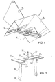
- the hood member shown in Fig. 1 is generally designated 2 and comprises a lower central vertical bushing 4 adapted to be engaged by a carrier pin of a stationary carrier structure such that the hood member will be freely rotatable about the axis of the bushing 4.
- the bushing 4 is rigidly connected with the bottom portion of an elongate narrow tray member 6, the opposed ends of which are secured, by welding or otherwise, to respective lower middle portions of the opposed side walls of a hood portion 8 constituted by a sheet metal member profiled with inverted V-shape, with a top angle preferably being approximately 90°.
- a bracket member 10 secured by welding or otherwise to a wide area of the underside of the tray bottom and having a top portion 12 associated with an upper end portion of the bushing 4.
- hood portion 8 Adjacent the lower edges of the opposed inner walls of the hood portion 8 are mounted straightlined water drain members 14 in such inclined positions that water flowing down the walls will run into the drain members and along these to their lower ends, which are located just above the respective ends of the tray member 6, i.e. the water is collected in the tray member.
- the hood portion 8 has a vane 16, which is a plate member mounted on one side of the hood 8 generally in the vertical cross middle plane thereof.
- Fig. 2 shows a support structure for the hood member 2. It comprises a central vertical pin 18 which projects upwardly from a carrier plate 20 having opposed widened end portions 22. Just inside these end portions there is secured to the underside of the carrier plate 20 a pair of opposed, arched collar members 24 shaped and located so as to at least roughly fit into the top opening of a chimney.
- the collar members 24 are each provided with a downwardly projecting leg member 26 having a lower outwardly arched portion 28. In their natural positions the leg members 26 are slightly diverging downwardly, but they are resilient such that they will clamp against the opposed sides of the chimney tube when the support structure is mounted topwise on the chimney with the end portions 22 of the member 20 rested against the top side of the chimney. Normally it will not be necessary to secure the structure to the chimney by further fastening means.
- the hood member 2 is mounted on the pin 18 by its bushing 4, and it may be anchored thereto, freely rotatable, by means of a cross pin 30 inserted through a top cross hole 32 in the pin 18 just above the top end of the mounted bushing 4. If desired a rotation bearing (not shown) may be placed between the lower end of the bushing 4 and the top side of the support plate 20.
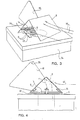
- FIG. 3 and 4 The assembled turncap as mounted on a chimney 34 is shown in Figs. 3 and 4. It will be readily understood that the vane 16 will operate to constantly maintain the hood portion 8 oriented cross-wise to the wind direction, as indicated by arrows w, whereby the smoke from the chimney opening (shown by arrow s) will have to leave the hood portion 8 through the opposed open lateral ends thereof. Though a certain suction action may be created by the wind passing across these open ends the resulting suction effect will be moderate, and the warm smoke gas will not be swept away instantaneously from the space inside the hood portion 8.
- the hood portion 8 may be made of a material such as aluminium coated steel plate which shows good radiation reflection properties in addition to being corrosion resistant.
- the tray 6 will normally be easily heatable to such an extent that the condensed water as continuously collected therein from the drain members 14 will be evaporated without overflowing the tray, whereby all problems as to the downlet of the condensed water are simply eliminated.
- the water as present in the tray may contain some soot or other impurities, but in practice the turncap may operate during a very long time without the tray being filled up by solid precipitations, while on the other hand a very minor amount of soot would be able to substantially miscolour the outside of the chimney if the water was caused to flow down from the hood member.
- a downflow through the chimney tube itself would be highly unrecommendable for various well known reasons.
- the pronouned inverted V-shape of the hood portion 8 is advantageous in that the water as condensed on the inside thereof will seek down along the inner hood surfaces without dripping down therefrom.
- Another advantage seems to be that the smoke gas as leaving the hood portion through the open ends thereof tends to be deflected upwardly, as shown by the arrow s in Fig. 4 and the wind arrow w, in Fig. 3, because the wind will create a subpressure on the leeward outside of the hood portion, whereby the pressure gradient across the downstream end edges of the hood portion will be rearwardly and upwardly directed.
- the smoke will tend to leave the turncap with an upwardly directed flow component as generally highly desirable.
- the particular design of the hood portion 8 accounts for certain pronounced advantages, and it will be noted that the design is nevertheless extremely simple.
- the design of the hood portion even conditions a very simple design of the drawin means 14 and 6 for the condensed water.
- the drain members 14 could be embodied by lowermost bent edge portions of the plate material of the hood portion 8 itself, but because the drain members should be inclined inwardly a possible resulting disadvantage would be that the opposed ends of the hood portion 8 would have their undersides spaced above the top of the chimney to such an extent that the wind could sweep across the very top surface of the chimney adjacent or underneath the ends of the hood portion 8, whereby the heat retaining effect of the hood portion would be reduced.
- a water collector (6) in rigid association with the carrier structure (Fig. 2) rather than with the rotary hood member 2, in which case, of course, the collector should be shaped so as to be able to receive the condensed water as drained off from the hood 2 irrespectively of the angular position of the hood member.
- a stationary collector could comprise a tray portion located either centrally underneath the pin 18 or as an annular member arranged concentrically with this pin and cooperating with an excentrically arranged downlet opening of a water collector system of the hood member 2.
- the evaporator tray should of course be located and designed such that it does not cause any blocking of the free outlet of smoke gas from the top of the chimney.
- the transverse orientation of the hood portion 8 seems advantageous not only with respect to the accumulation of the heat for evaporating the condensed water, but even for the operation conditions of the furnace or firing place.
- a reduced tendency to occurance of return smoke has been noted, and the effect of the hood may be changed or adjusted to specific circumstances by another design of e.g. the side openings of the hood portion; in the embodiment shown these openings are defined by edges located in a common plane which is orthogonal to the longitudinal direction of the hood portion, but the opening plane may well be oblique, e.g. upwardly and outwardly and/or rearwardly and inwardly.
- the opening planes would of course not need to be planar, and even the length of the hood portion and its length/width-ratio may be selected for optimal operation.
- the chimney sweeper will have easy access to the chimney, since he can just retract the entire turncap structure from the chimney and remount it when the work has been done.
- a hole 36 in the top end of the vane 16 is adapted to be engaged by the sweeper's snap hook for safe carrying of the turncap structure during the sweeping work.
- the bushing 4 is replaced by a . drawn up collar portion of the bottom of the tray 6, such that the water cannot leave the tray through the corresponding hole.
- the collar projects only slightly upwardly, and the pin 18 is received through the said hole and the hole in the top portion 12 of the U-member 10.
- On the lower end of the pin 18 is placed a washer of stainless steel, and the flat underside of the U-member 10 bears direct on this washer.
Landscapes
- Engineering & Computer Science (AREA)
- Mechanical Engineering (AREA)
- Chemical & Material Sciences (AREA)
- Combustion & Propulsion (AREA)
- General Engineering & Computer Science (AREA)
- Robotics (AREA)
- Physics & Mathematics (AREA)
- Manufacturing & Machinery (AREA)
- Human Computer Interaction (AREA)
- General Physics & Mathematics (AREA)
- Automation & Control Theory (AREA)
- Health & Medical Sciences (AREA)
- General Health & Medical Sciences (AREA)
- Orthopedic Medicine & Surgery (AREA)
- Separating Particles In Gases By Inertia (AREA)
- Rear-View Mirror Devices That Are Mounted On The Exterior Of The Vehicle (AREA)
- Soil Working Implements (AREA)
Priority Applications (1)
| Application Number | Priority Date | Filing Date | Title |
|---|---|---|---|
| AT82900355T ATE11174T1 (de) | 1981-01-28 | 1982-01-26 | Sich drehende kaminabdeckung. |
Applications Claiming Priority (2)
| Application Number | Priority Date | Filing Date | Title |
|---|---|---|---|
| DK37081A DK37081A (da) | 1981-01-28 | 1981-01-28 | Roeghat |
| DK370/81 | 1981-01-28 |
Publications (2)
| Publication Number | Publication Date |
|---|---|
| EP0070848A1 EP0070848A1 (en) | 1983-02-09 |
| EP0070848B1 true EP0070848B1 (en) | 1985-01-09 |
Family
ID=8092741
Family Applications (1)
| Application Number | Title | Priority Date | Filing Date |
|---|---|---|---|
| EP82900355A Expired EP0070848B1 (en) | 1981-01-28 | 1982-01-26 | A chimney turncap |
Country Status (8)
| Country | Link |
|---|---|
| US (1) | US4487112A (OSRAM) |
| EP (1) | EP0070848B1 (OSRAM) |
| JP (1) | JPS57502228A (OSRAM) |
| BE (1) | BE891918A (OSRAM) |
| DE (1) | DE3261788D1 (OSRAM) |
| DK (1) | DK37081A (OSRAM) |
| NO (1) | NO151513C (OSRAM) |
| WO (1) | WO1982002586A1 (OSRAM) |
Families Citing this family (6)
| Publication number | Priority date | Publication date | Assignee | Title |
|---|---|---|---|---|
| US4727796A (en) * | 1986-10-28 | 1988-03-01 | Derkach W George | Weather cap for upstanding exhaust pipes |
| AUPR821601A0 (en) * | 2001-10-12 | 2001-11-01 | Ambrose, Wallace Raymond | Tilting hood ventilator |
| USD545423S1 (en) * | 2006-05-30 | 2007-06-26 | Russell Delallo | Chimney protector |
| TW201243245A (en) * | 2011-04-25 | 2012-11-01 | Univ Nat Pingtung Sci & Tech | Airway |
| CN108124396B (zh) * | 2017-11-17 | 2021-06-08 | 许继电气股份有限公司 | 户外柜及其顶盖 |
| CN116042939A (zh) * | 2022-12-28 | 2023-05-02 | 国家电投集团远达环保工程有限公司 | 一种适用于烟囱顶部的防结冰装置 |
Family Cites Families (13)
| Publication number | Priority date | Publication date | Assignee | Title |
|---|---|---|---|---|
| US439494A (en) * | 1890-10-28 | Stove-pipe cowl attachment | ||
| DK3734C (da) * | 1901-02-25 | Hugo John | Sammenlæggelig Skorstensopsats med drejelig Hætte. | |
| US720210A (en) * | 1902-02-11 | 1903-02-10 | Frederic Wunderlich | Chimney-top. |
| US846446A (en) * | 1906-10-01 | 1907-03-12 | William R A Ball | Chimney-cowl. |
| GB190805215A (en) * | 1908-03-07 | 1909-03-08 | Harry Coverdale | Improvements in Chimney Tops or Ventilating Terminals. |
| GB190914171A (en) * | 1909-06-16 | 1910-06-16 | Antoni Klempnerowski | Improvements in Cowls for Increasing the Draught in Chimneys or Ventilation Shafts. |
| US1332239A (en) * | 1919-04-19 | 1920-03-02 | Elibert B Tonnsen | Ventilator |
| DK31329C (da) * | 1920-10-08 | 1923-02-26 | Fabrikanter Af Opvarmnings Og | Ventilationshætte, ved hvilken den indtrædende Fugtighed nedfældes og afledes. |
| US1626002A (en) * | 1921-12-06 | 1927-04-26 | Lobit Jean Martial | Flue |
| US2501011A (en) * | 1948-01-27 | 1950-03-21 | Smart Lee | Moisture guard for chimneys |
| US2766678A (en) * | 1954-03-04 | 1956-10-16 | Wayne E Morris | Chimney cap |
| DE1247533B (de) * | 1966-02-26 | 1967-08-17 | Rheinquell Ets | Schornsteinaufsatz |
| DE2649759C3 (de) * | 1976-10-29 | 1979-09-06 | Otto 8076 Ebenhausen Gloeser | Aufsatzstein für Kamine |
-
1981
- 1981-01-28 DK DK37081A patent/DK37081A/da unknown
-
1982
- 1982-01-26 DE DE8282900355T patent/DE3261788D1/de not_active Expired
- 1982-01-26 WO PCT/DK1982/000005 patent/WO1982002586A1/en not_active Ceased
- 1982-01-26 US US06/432,906 patent/US4487112A/en not_active Expired - Fee Related
- 1982-01-26 JP JP57500429A patent/JPS57502228A/ja active Pending
- 1982-01-26 EP EP82900355A patent/EP0070848B1/en not_active Expired
- 1982-01-28 BE BE2/59558A patent/BE891918A/fr not_active IP Right Cessation
- 1982-09-13 NO NO823100A patent/NO151513C/no unknown
Also Published As
| Publication number | Publication date |
|---|---|
| DE3261788D1 (en) | 1985-02-21 |
| NO151513C (no) | 1985-04-24 |
| NO151513B (no) | 1985-01-07 |
| JPS57502228A (OSRAM) | 1982-12-16 |
| NO823100L (no) | 1982-09-13 |
| WO1982002586A1 (en) | 1982-08-05 |
| DK37081A (da) | 1982-07-29 |
| BE891918A (fr) | 1982-07-28 |
| US4487112A (en) | 1984-12-11 |
| EP0070848A1 (en) | 1983-02-09 |
Similar Documents
| Publication | Publication Date | Title |
|---|---|---|
| US4435925A (en) | Shield for eaves drain gutter | |
| CA2371455C (en) | Passive venting device | |
| US4418685A (en) | Roof-mounted solar collector device | |
| US4395852A (en) | Gutter guard | |
| EP0070848B1 (en) | A chimney turncap | |
| US20010017008A1 (en) | Roof valley water collector | |
| NO318663B1 (no) | System for oppvarming av satellittantenne | |
| US5127200A (en) | Eavestrough debris protection mechanism | |
| US5081914A (en) | Roof vent cap | |
| US4117833A (en) | Exhaust hood with adjustable air injection nozzle | |
| CA3063778C (en) | Roof vent with integrated shield | |
| CA1183713A (en) | Chimney turncap | |
| US3398671A (en) | Roof ventilator with u-shaped flue cap | |
| US4781401A (en) | Adjustable jack for mounting on a duct bend | |
| US4089188A (en) | Evaporator coil | |
| US4583494A (en) | Heat recovery apparatus and heat recovery method | |
| US3795271A (en) | Device for melting and preventing the formation of ice in the area of the edge of a roof | |
| US3425178A (en) | Rain trap for prefabricated metal chimney | |
| AU5437898A (en) | Static venting system | |
| US4003407A (en) | Drip-preventing condensation shroud usable with water heaters | |
| US4161940A (en) | Telescopic heat control deflector | |
| SU1239469A1 (ru) | Приточно-выт жное устройство | |
| EP0679841B2 (en) | Assembly of air supply pipe and/or flue gas discharge pipe for connection to a furnace | |
| DK156522B (da) | Skorstenshaette af drejetypen | |
| US4467960A (en) | Combination weathervane heat exchanger |
Legal Events
| Date | Code | Title | Description |
|---|---|---|---|
| PUAI | Public reference made under article 153(3) epc to a published international application that has entered the european phase |
Free format text: ORIGINAL CODE: 0009012 |
|
| AK | Designated contracting states |
Designated state(s): AT CH DE FR GB LI NL SE |
|
| 17P | Request for examination filed |
Effective date: 19830203 |
|
| GRAA | (expected) grant |
Free format text: ORIGINAL CODE: 0009210 |
|
| AK | Designated contracting states |
Designated state(s): AT CH DE FR GB LI NL SE |
|
| REF | Corresponds to: |
Ref document number: 11174 Country of ref document: AT Date of ref document: 19850115 Kind code of ref document: T |
|
| REF | Corresponds to: |
Ref document number: 3261788 Country of ref document: DE Date of ref document: 19850221 |
|
| ET | Fr: translation filed | ||
| PLBE | No opposition filed within time limit |
Free format text: ORIGINAL CODE: 0009261 |
|
| STAA | Information on the status of an ep patent application or granted ep patent |
Free format text: STATUS: NO OPPOSITION FILED WITHIN TIME LIMIT |
|
| 26N | No opposition filed | ||
| PGFP | Annual fee paid to national office [announced via postgrant information from national office to epo] |
Ref country code: FR Payment date: 19921228 Year of fee payment: 12 |
|
| PGFP | Annual fee paid to national office [announced via postgrant information from national office to epo] |
Ref country code: CH Payment date: 19930111 Year of fee payment: 12 |
|
| PGFP | Annual fee paid to national office [announced via postgrant information from national office to epo] |
Ref country code: SE Payment date: 19930115 Year of fee payment: 12 |
|
| PGFP | Annual fee paid to national office [announced via postgrant information from national office to epo] |
Ref country code: GB Payment date: 19930118 Year of fee payment: 12 |
|
| PGFP | Annual fee paid to national office [announced via postgrant information from national office to epo] |
Ref country code: DE Payment date: 19930126 Year of fee payment: 12 |
|
| PGFP | Annual fee paid to national office [announced via postgrant information from national office to epo] |
Ref country code: AT Payment date: 19930129 Year of fee payment: 12 |
|
| PGFP | Annual fee paid to national office [announced via postgrant information from national office to epo] |
Ref country code: NL Payment date: 19930131 Year of fee payment: 12 |
|
| PG25 | Lapsed in a contracting state [announced via postgrant information from national office to epo] |
Ref country code: GB Effective date: 19940126 Ref country code: AT Effective date: 19940126 |
|
| PG25 | Lapsed in a contracting state [announced via postgrant information from national office to epo] |
Ref country code: SE Effective date: 19940127 |
|
| PG25 | Lapsed in a contracting state [announced via postgrant information from national office to epo] |
Ref country code: CH Effective date: 19940131 Ref country code: LI Effective date: 19940131 |
|
| PG25 | Lapsed in a contracting state [announced via postgrant information from national office to epo] |
Ref country code: NL Effective date: 19940801 |
|
| NLV4 | Nl: lapsed or anulled due to non-payment of the annual fee | ||
| GBPC | Gb: european patent ceased through non-payment of renewal fee |
Effective date: 19940126 |
|
| PG25 | Lapsed in a contracting state [announced via postgrant information from national office to epo] |
Ref country code: FR Effective date: 19940930 |
|
| REG | Reference to a national code |
Ref country code: CH Ref legal event code: PL |
|
| PG25 | Lapsed in a contracting state [announced via postgrant information from national office to epo] |
Ref country code: DE Effective date: 19941001 |
|
| REG | Reference to a national code |
Ref country code: FR Ref legal event code: ST |
|
| EUG | Se: european patent has lapsed |
Ref document number: 82900355.7 Effective date: 19940810 |