EP0070762B1 - Dispositif de commande électronique d'une boîte de vitesses manuelle ou automatique - Google Patents
Dispositif de commande électronique d'une boîte de vitesses manuelle ou automatique Download PDFInfo
- Publication number
- EP0070762B1 EP0070762B1 EP19820401277 EP82401277A EP0070762B1 EP 0070762 B1 EP0070762 B1 EP 0070762B1 EP 19820401277 EP19820401277 EP 19820401277 EP 82401277 A EP82401277 A EP 82401277A EP 0070762 B1 EP0070762 B1 EP 0070762B1
- Authority
- EP
- European Patent Office
- Prior art keywords
- state
- bits
- logic
- binary
- word
- Prior art date
- Legal status (The legal status is an assumption and is not a legal conclusion. Google has not performed a legal analysis and makes no representation as to the accuracy of the status listed.)
- Expired
Links
- 230000005540 biological transmission Effects 0.000 title description 2
- 230000008859 change Effects 0.000 claims description 8
- 230000004913 activation Effects 0.000 claims description 7
- 230000006870 function Effects 0.000 claims description 7
- 230000007935 neutral effect Effects 0.000 claims description 7
- 101100166845 Arabidopsis thaliana CESA3 gene Proteins 0.000 claims description 6
- 230000001960 triggered effect Effects 0.000 claims description 6
- 230000008878 coupling Effects 0.000 claims description 5
- 238000010168 coupling process Methods 0.000 claims description 5
- 238000005859 coupling reaction Methods 0.000 claims description 5
- 239000003990 capacitor Substances 0.000 claims description 3
- 230000003111 delayed effect Effects 0.000 claims 1
- 230000007704 transition Effects 0.000 description 4
- 230000003213 activating effect Effects 0.000 description 3
- 230000009471 action Effects 0.000 description 2
- 235000021183 entrée Nutrition 0.000 description 2
- 230000005284 excitation Effects 0.000 description 2
- 230000001052 transient effect Effects 0.000 description 2
- 101000983970 Conus catus Alpha-conotoxin CIB Proteins 0.000 description 1
- 241000897276 Termes Species 0.000 description 1
- 230000000903 blocking effect Effects 0.000 description 1
- 239000013256 coordination polymer Substances 0.000 description 1
- 230000009849 deactivation Effects 0.000 description 1
- 230000001934 delay Effects 0.000 description 1
- 238000010586 diagram Methods 0.000 description 1
- 239000012530 fluid Substances 0.000 description 1
- 230000010355 oscillation Effects 0.000 description 1
- 230000035484 reaction time Effects 0.000 description 1
Images

Classifications
-
- F—MECHANICAL ENGINEERING; LIGHTING; HEATING; WEAPONS; BLASTING
- F16—ENGINEERING ELEMENTS AND UNITS; GENERAL MEASURES FOR PRODUCING AND MAINTAINING EFFECTIVE FUNCTIONING OF MACHINES OR INSTALLATIONS; THERMAL INSULATION IN GENERAL
- F16H—GEARING
- F16H61/00—Control functions within control units of change-speed- or reversing-gearings for conveying rotary motion ; Control of exclusively fluid gearing, friction gearing, gearings with endless flexible members or other particular types of gearing
- F16H61/02—Control functions within control units of change-speed- or reversing-gearings for conveying rotary motion ; Control of exclusively fluid gearing, friction gearing, gearings with endless flexible members or other particular types of gearing characterised by the signals used
- F16H61/0202—Control functions within control units of change-speed- or reversing-gearings for conveying rotary motion ; Control of exclusively fluid gearing, friction gearing, gearings with endless flexible members or other particular types of gearing characterised by the signals used the signals being electric
- F16H61/0204—Control functions within control units of change-speed- or reversing-gearings for conveying rotary motion ; Control of exclusively fluid gearing, friction gearing, gearings with endless flexible members or other particular types of gearing characterised by the signals used the signals being electric for gearshift control, e.g. control functions for performing shifting or generation of shift signal
- F16H61/0213—Control functions within control units of change-speed- or reversing-gearings for conveying rotary motion ; Control of exclusively fluid gearing, friction gearing, gearings with endless flexible members or other particular types of gearing characterised by the signals used the signals being electric for gearshift control, e.g. control functions for performing shifting or generation of shift signal characterised by the method for generating shift signals
-
- F—MECHANICAL ENGINEERING; LIGHTING; HEATING; WEAPONS; BLASTING
- F16—ENGINEERING ELEMENTS AND UNITS; GENERAL MEASURES FOR PRODUCING AND MAINTAINING EFFECTIVE FUNCTIONING OF MACHINES OR INSTALLATIONS; THERMAL INSULATION IN GENERAL
- F16H—GEARING
- F16H2306/00—Shifting
- F16H2306/40—Shifting activities
- F16H2306/52—Applying torque to new gears
-
- F—MECHANICAL ENGINEERING; LIGHTING; HEATING; WEAPONS; BLASTING
- F16—ENGINEERING ELEMENTS AND UNITS; GENERAL MEASURES FOR PRODUCING AND MAINTAINING EFFECTIVE FUNCTIONING OF MACHINES OR INSTALLATIONS; THERMAL INSULATION IN GENERAL
- F16H—GEARING
- F16H61/00—Control functions within control units of change-speed- or reversing-gearings for conveying rotary motion ; Control of exclusively fluid gearing, friction gearing, gearings with endless flexible members or other particular types of gearing
- F16H61/68—Control functions within control units of change-speed- or reversing-gearings for conveying rotary motion ; Control of exclusively fluid gearing, friction gearing, gearings with endless flexible members or other particular types of gearing specially adapted for stepped gearings
- F16H61/684—Control functions within control units of change-speed- or reversing-gearings for conveying rotary motion ; Control of exclusively fluid gearing, friction gearing, gearings with endless flexible members or other particular types of gearing specially adapted for stepped gearings without interruption of drive
- F16H61/686—Control functions within control units of change-speed- or reversing-gearings for conveying rotary motion ; Control of exclusively fluid gearing, friction gearing, gearings with endless flexible members or other particular types of gearing specially adapted for stepped gearings without interruption of drive with orbital gears
Definitions
- the invention relates to an electronic control device for a manual or automatic gearbox comprising several forward gear ratios and at least one reverse gear.
- a device applies to the control of a gearbox of the kind in which the different states of the box are obtained by the control of a number p of solenoid valves, p being greater than the number n of reports , authorizing the passage of a pressurized fluid which determines the tightening of braking members or coupling in rotation of elements of the box and in particular of planetary gear trains.
- each state is obtained by activating one or more of the solenoid valves, the others being deactivated.
- the transition from a first state to a second state will therefore be effected by deactivating the solenoid valves participating in the first state but not in the second and by activating those which participate in the second state but not in the first.
- the set of solenoid valves which must be activated to obtain a third state is only composed of solenoid valves, some of which are activated in the first state and the others in the second state, it is generally necessary to delay the tightening of the participating coupling members both in the second and in the third state, this to avoid an unwanted transient transition into the third state. This is achieved either by a hydraulic passage delay, or by electronic means delaying the control of the solenoid valves concerned.
- an electronic control device of an automatic gearbox comprising a plurality (n) of forward gear ratios and at least one reverse gear, of the type in which the different states of the box are obtained by controlling a plurality (P) of solenoid valves acting on braking or rotationally coupling elements of the box, the sequence of control of the solenoid valves making it possible to obtain a given state of the box being developed by logic means from control signals whose logic state 1 or 0 corresponds for each to the control of this state, this device comprising binary decoding means developing from the logic state of the control signals, the value 0 or 1 of each bit of a logic signal which, applied to the inputs of a logic circuit, outputs a word of several bits, whose number (P) of bits is the same as the number of solenoid valves and whose state 0 or 1 of each bit is respectively applied to an input of the power control means of one of the solenoid valves.
- the object of the invention is improvements to electronic control devices of the above type in order to improve their operating reliability and the possibilities for adjusting the gear change times.
- a device is characterized in that the logic circuit is a read only memory and the logic signal produced by the binary decoding means constitutes the address calling in the read only memory the word of several bits and in that the input of the power control circuit of at least one solenoid valve comprises an AND logic circuit, one input of which receives the state 0 or 1 of the bit assigned to the control of this solenoid valve and another input a logic signal 1 deferred by a delay means triggered by the binary decoding means simultaneously with the addressing of the memory word.
- Each memory word is thus representative of the state in which each solenoid valve must be in order for the commanded state to be achieved regardless of the previous state and the tightening delay time is counted from the moment when the order to deactivate the solenoid valves participating in the previous state is effectively given.
- the logic means of binary type comprise a comparator comparing the binary number N1 of n bits composed by the n control signals of the forward gears taken in a sequence corresponding to the successive order of the n gears and of the value N2 taken by an up-down counter with n bits incremented or decremented under the control of the comparator until N2 is equal to N1, first logic means delivering as a function of N2 at least n bits of the address of the memory word and second logic means delivering, as a function of the changes in position of a lever for selecting forward / neutral / reverse and from N2 the other bits of the memory address.
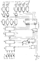
- the device shown in FIG. 1 applies to the manual control of a gearbox with 4 forward gears and one reverse gear.
- the gearbox (not shown) comprises 6 braking means or coupling in rotation of planetary gear elements. Each of these means is controlled by a solenoid valve EV1 to EV6 controlled by a power control means CEV1 to CEV6 respectively.
- the lever 1 for selecting forward / neutral / reverse gear being placed in the AV position, the control of a forward gear ratio is carried out by pressing one of the 4 pushbuttons P1 to P4, respectively assigned to the gears 1 to 4.
- Pressing a push button generates a control pulse from a + 5 V DC voltage source.
- a comparator CI.2 compares the binary number N1 representing the commanded state with a binary number N2 of 4 bits delivered by an up-down counter C1.3.
- the comparator CI.2 can be produced by a circuit MC 14585 from the company MOTOROLA.
- the down counter Ci.3 can be realized from a circuit MC 14510 of the same Company.
- the comparator CI.2 starts an oscillator Cl.4 and positions the up-down counter in up-counting mode or in down-counting mode depending on whether N1 is higher or lower than N2.
- the oscillations of Cl.4, used as clock, are applied to the counting input CP of the up-down counter Cl.3.
- the value of N2 is therefore incremented or decremented at the rate of the clock according to the direction of the result of the comparison.
- the comparator stops the oscillator CI. 4.
- the state of each of the n bits of the binary number N2 is respectively applied on the one hand to one of the n inputs of first logic means L1 and on the other hand to one of the inputs of second logic means L2.
- the first logic means L1 comprise a binary decoder CI.6 which delivers, as a function of the binary number N2, a binary word N3 of m bits to a logic circuit L3 (with m greater than n).
- the logic circuit L3 delivers 4 bits A1, A2, A3 and A4 from the address of a read-only memory Cl.5.
- Other bits AO and A5 of the 6-bit address of a memory word are supplied by the logic means L2.
- the memory Cl.5 delivers on its outputs Q0 to Q5 the 6 bits of a memory word.
- Each bit Q0 to Q5 is assigned to the control of a power control means CEV1 to CEV6 of the solenoid valves EV1 to EV6.
- the address and the words of the memory CI.5 can comprise more than 6 bits, the superfluous bits being neutralized.
- the state of the control bit (Q4, Q2 and 01 respectively) is directly applied to the power control means of the solenoid valve.
- This power means is an amplifier with logic control, produced in a known manner, which delivers to the solenoid valve the current necessary for its activation when the control bit which is assigned to it is at state 1 and cuts this current when the bit is at state 0.
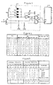
- the timing means are triggered by the circuit L3 as a function of the changes of state of the word N3 according to a logic which will be explained with reference to the table in FIG. 5 showing the correspondence between the address and the memory word delivered, each memory word corresponds to a state of the box obtained by activation of a group of solenoid valves, the activation of the same solenoid valve being able to intervene for several states.
- the solenoid valve EV2 (control bit Q3) must be activated to obtain the 2nd report and also to obtain the 4th report.
- the activation of the solenoid valve EV2 is timed by the means Tp2 for the passage of the 3rd or 2nd gear and by the means Tp3 for the passage of the 3rd or 4th gear.
- the EV3 solenoid valve is timed by means Tp4 for the passage of the 4th or 3rd gear.
- the values 0 or 1 of the bits AO and A5 of the address of the memory word are determined by the logic means L2 as a function of the binary number N2 and of the state 0 or 1 of two signals AV and AR determined by the position of the lever selection 1.
- the 4 bits of N2 are each applied to an input of an OR gate constituted by the 4 diodes D1, D2, D3, and D4 and the resistor R1 (Fig.3).
- the output signal of this gate is inverted by an inverter IN1 and applied to an input of each of the AND gates, EO and E5.
- the second input of door EO receives the signal AV (value 1 in forward and 0 in reverse and in neutral) and the second input of door E5 receives the signal AR (value 1 in reverse and 0 in forward and in neutral).
- the output of gate EO gives the address bit A0, that of gate E5 the address bit A5. It can be seen that this arrangement gives the bits AO and A5, depending on the state of the control means, the values in the table of FIG. 5.
- the 8 outputs used from the C1.6 decoder, usually referenced 01 to Q8, are referenced S1 to S8 to avoid confusion with the outputs 0 of the memory CI.5.
- the outputs S1 to S8 are connected to the inputs A1 to A4 of the memory Cl.5 by the diodes D5 to D12 polarized by the resistors R2 to R5 to obtain logic conforming to the table in Fig.4.
- the set of diodes D7 to D10 and the resistor R4 constitute an OR gate whose output provides the address bit A3 whose state is therefore 1 if at least one of the outputs S3 to S6 is in state 1 It is the same for the diodes D11 and D12 and the resistor R5, the address bit A4 is at 1 if one of the outputs S7 or S8 is at 1.
- the state of the address bits A1 and A2 corresponds respectively to that of outputs S1 and S2.
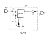
- the delay means Tp1 to Tp4 use monostable circuits, for example of the LM122 type from the National Semi Conductive Company mounted with an inverter IN2 at the output according to FIG. which represents the time delay Tp1 placed between gate NE1 and gate E1.
- the duration of the delay is determined by the choice of C5, C6, R6 and R7.
- each time delay Tp1 to Tp4 is connected to the output of a NAND logic gate respectively NE1 to NE4.
- a first input of each of these gates is directly connected to a first output Sn of the decoder CI.6, the second input being connected to a second output Sp of the decoder by a diode (respectively D21 to D24) and to ground by a capacitor (respectively C1 to C4).
- the diodes D21 to D24 are shunted by a resistor (respectively R21 to R24).
- the activation of a timer is done as follows.
- the output of a gate NE1 to NE4 is at state 0 if its two inputs are at state 1, and at state 1 in all other cases.
- the time delay is put into action, either during an increment of N2 (upshifts), or during a decrementation of N2 (downshifts), depending on whether the Sn connections of the first inputs and Sp of the second inputs of the NAND gate correspond to n> p or n ⁇ p.
- the timers Tp1, Tp2, Tp3 and Tp4 corresponding respectively to passages 2 - 3, 3 - 2, 3 ⁇ 4, 4 ⁇ 3 are put into action by the inversion of state 1 respectively of outputs S2 and S3, S4 and S2, S6 and S7, S7 and S6. It is clear from examining the table in FIG.
- the excitation of the solenoid valve EV3 is maintained and the excitation of the EV4 solenoid valve causes the 1st forward gear to pass.
- the timer Tp4 did not work since the inputs of the gate NE4 are connected to the outputs S7 and S6 of the decoder which have not varied.
- N2 will then be incremented at the rate of the oscillator Ci.4 until it reaches the value of N1, ie 1000.
- N2 0010
- N3 0000 0010
- address 000100
- memory word 001101.
- the transition from state 1 of output S1 to output S2 of the decoder does not command any time delay.
- the 2nd report is obtained by simultaneously deactivating the .EV4 solenoid valve and activating the EV2 and EV5 solenoid valves.
- the timer Tp1 is triggered by the change from state 1 of output S2 to output S3 of the decoder.
- the solenoid valve EV2 is deactivated by setting the bit Q3 to 0 and the solenoid valve EV1 is activated at the end of the delay time, which causes the shift to the 3rd gear.
- the subsequent increments of N2 up to the value 0110 do not cause the addressing and therefore the memory word to be modified.
- the timer Tp3 is triggered by the change from state 1 of output S6 to output S7 of the decoder.
- the EV3 solenoid valve is deactivated by setting the Q3 bit to 0 and the EV2 solenoid valve is activated at the end of the time delay, which causes the 4th gear to be shifted.
- the operation would be similar if instead of mounting reports, we wanted to downshift.
- the device thus brings whatever the difference between the previously engaged report and the ordered report, the successive passage of the gearbox in the intermediate reports.
- the clock frequency is of course chosen to be quite low, corresponding to a cycle time of 100 to 300 milli-seconds, to ensure compatibility with the reaction times of the hydraulic device to be controlled.
- the binary number N1 representing the commanded state would be developed in a known manner by control means sensitive to the operating parameters of the vehicle.
Landscapes
- Engineering & Computer Science (AREA)
- General Engineering & Computer Science (AREA)
- Mechanical Engineering (AREA)
- Control Of Transmission Device (AREA)
Applications Claiming Priority (2)
| Application Number | Priority Date | Filing Date | Title |
|---|---|---|---|
| FR8114268 | 1981-07-22 | ||
| FR8114268A FR2510050A1 (fr) | 1981-07-22 | 1981-07-22 | Dispositif de commande electronique d'une boite de vitesses manuelle ou automatique |
Publications (3)
| Publication Number | Publication Date |
|---|---|
| EP0070762A2 EP0070762A2 (fr) | 1983-01-26 |
| EP0070762A3 EP0070762A3 (en) | 1983-12-07 |
| EP0070762B1 true EP0070762B1 (fr) | 1986-03-26 |
Family
ID=9260764
Family Applications (1)
| Application Number | Title | Priority Date | Filing Date |
|---|---|---|---|
| EP19820401277 Expired EP0070762B1 (fr) | 1981-07-22 | 1982-07-06 | Dispositif de commande électronique d'une boîte de vitesses manuelle ou automatique |
Country Status (3)
| Country | Link |
|---|---|
| EP (1) | EP0070762B1 (OSRAM) |
| DE (1) | DE3270090D1 (OSRAM) |
| FR (1) | FR2510050A1 (OSRAM) |
Families Citing this family (1)
| Publication number | Priority date | Publication date | Assignee | Title |
|---|---|---|---|---|
| FR2600285B1 (fr) * | 1986-06-20 | 1988-10-07 | Renault | Dispositif de commande electromecanique de boite de vitesses automatique |
Family Cites Families (4)
| Publication number | Priority date | Publication date | Assignee | Title |
|---|---|---|---|---|
| US3448640A (en) * | 1967-06-30 | 1969-06-10 | Gen Motors Corp | Electrical control for automatic transmission |
| US3983405A (en) * | 1974-12-19 | 1976-09-28 | Donovan John S | Shift control system for multi-stage transmission |
| DE2700962C3 (de) * | 1977-01-12 | 1981-10-29 | Zahnradfabrik Friedrichshafen Ag, 7990 Friedrichshafen | Elektrohydraulische Gagnwechseleinrichutng eines lastschaltbaren Wechselgetriebes für Kraftfahrzeuge |
| US4148231A (en) * | 1977-04-25 | 1979-04-10 | Clark Equipment Company | Automatic transmission control |
-
1981
- 1981-07-22 FR FR8114268A patent/FR2510050A1/fr active Granted
-
1982
- 1982-07-06 EP EP19820401277 patent/EP0070762B1/fr not_active Expired
- 1982-07-06 DE DE8282401277T patent/DE3270090D1/de not_active Expired
Also Published As
| Publication number | Publication date |
|---|---|
| EP0070762A3 (en) | 1983-12-07 |
| FR2510050B1 (OSRAM) | 1984-04-27 |
| EP0070762A2 (fr) | 1983-01-26 |
| DE3270090D1 (en) | 1986-04-30 |
| FR2510050A1 (fr) | 1983-01-28 |
Similar Documents
| Publication | Publication Date | Title |
|---|---|---|
| US4155277A (en) | Automatic speed change control apparatus | |
| CH674113A5 (OSRAM) | ||
| FR2474190A1 (fr) | Dispositif et procede de commande d'une machine comportant un outil d'usinage d'une piece | |
| FR2563955A1 (fr) | Circuit retardateur de signaux numeriques | |
| FR2638303A1 (fr) | Filtre interpolatif perfectionne | |
| EP0130645B1 (fr) | Diviseur de fréquence par deux | |
| FR2501437A1 (fr) | Convertisseur serie-parallele | |
| EP0070762B1 (fr) | Dispositif de commande électronique d'une boîte de vitesses manuelle ou automatique | |
| EP0475862B1 (fr) | Compteur/diviseur rapide et application à un compteur avaleur | |
| EP0442829B1 (fr) | Doubleur de fréquence d'horloge | |
| EP0092464B1 (fr) | Compteur avec sauvegarde non-volatile de son contenu | |
| EP0683441A1 (fr) | Montre électronique avec fonction répétition minutes | |
| FR2522826A1 (fr) | Dispositif de generation numerique d'un signal module en frequence et dispositif radiofrequence comprenant un tel dispositif numerique | |
| EP0591813B1 (fr) | Modulateur à phase continue | |
| CA2040650C (fr) | Circuit de multiplexage de signaux d'horloge | |
| EP0302562B1 (fr) | Synthétiseur de fréquences présentant un dispositif indicateur d'accord | |
| FR2575880A1 (fr) | Diviseur de frequences | |
| FR2527802A1 (fr) | Convertisseur incrementiel-numerique | |
| FR2877164A1 (fr) | Dispositif de bascule en particulier du type a retention d'etat declenchee sur fronts | |
| FR2517145A1 (fr) | Circuit diviseur a rapport reglable et synthetiseur de frequence | |
| EP0246135B1 (fr) | Détécteur de phase et de fréquence, et son utilisation dans une boucle à verrouillage de phase | |
| EP0169089B1 (fr) | Dispositif élémentaire de traitement de données | |
| FR2591830A1 (fr) | Circuit pour le traitement numerique de series d'impulsions a phases multiples d'un generateur d'impulsions | |
| FR2589019A1 (fr) | Porte logique a coincidence, triplet de portes logiques et circuit logique sequentiel mettant en oeuvre cette porte logique | |
| FR2710208A1 (fr) | Intégrateur et filtre du premier ordre numériques. |
Legal Events
| Date | Code | Title | Description |
|---|---|---|---|
| PUAI | Public reference made under article 153(3) epc to a published international application that has entered the european phase |
Free format text: ORIGINAL CODE: 0009012 |
|
| AK | Designated contracting states |
Designated state(s): DE GB IT |
|
| PUAL | Search report despatched |
Free format text: ORIGINAL CODE: 0009013 |
|
| AK | Designated contracting states |
Designated state(s): DE GB IT |
|
| 17P | Request for examination filed |
Effective date: 19840201 |
|
| GRAA | (expected) grant |
Free format text: ORIGINAL CODE: 0009210 |
|
| AK | Designated contracting states |
Kind code of ref document: B1 Designated state(s): DE GB IT |
|
| ITF | It: translation for a ep patent filed | ||
| REF | Corresponds to: |
Ref document number: 3270090 Country of ref document: DE Date of ref document: 19860430 |
|
| PLBE | No opposition filed within time limit |
Free format text: ORIGINAL CODE: 0009261 |
|
| STAA | Information on the status of an ep patent application or granted ep patent |
Free format text: STATUS: NO OPPOSITION FILED WITHIN TIME LIMIT |
|
| 26N | No opposition filed | ||
| ITTA | It: last paid annual fee | ||
| PGFP | Annual fee paid to national office [announced via postgrant information from national office to epo] |
Ref country code: GB Payment date: 19940627 Year of fee payment: 13 |
|
| PGFP | Annual fee paid to national office [announced via postgrant information from national office to epo] |
Ref country code: DE Payment date: 19940930 Year of fee payment: 13 |
|
| PG25 | Lapsed in a contracting state [announced via postgrant information from national office to epo] |
Ref country code: GB Effective date: 19950706 |
|
| GBPC | Gb: european patent ceased through non-payment of renewal fee |
Effective date: 19950706 |
|
| PG25 | Lapsed in a contracting state [announced via postgrant information from national office to epo] |
Ref country code: DE Effective date: 19960402 |