EP0070247A2 - Universal anti-theft device, especially for nuts and bolts to fix car-wheels - Google Patents
Universal anti-theft device, especially for nuts and bolts to fix car-wheels Download PDFInfo
- Publication number
- EP0070247A2 EP0070247A2 EP82420100A EP82420100A EP0070247A2 EP 0070247 A2 EP0070247 A2 EP 0070247A2 EP 82420100 A EP82420100 A EP 82420100A EP 82420100 A EP82420100 A EP 82420100A EP 0070247 A2 EP0070247 A2 EP 0070247A2
- Authority
- EP
- European Patent Office
- Prior art keywords
- adapter
- drive member
- imprint
- nut
- complementary
- Prior art date
- Legal status (The legal status is an assumption and is not a legal conclusion. Google has not performed a legal analysis and makes no representation as to the accuracy of the status listed.)
- Withdrawn
Links
- 230000000295 complement effect Effects 0.000 claims abstract description 7
- 239000000853 adhesive Substances 0.000 claims description 3
- 230000001070 adhesive effect Effects 0.000 claims description 3
- 238000010791 quenching Methods 0.000 claims description 3
- 230000000171 quenching effect Effects 0.000 claims description 3
- 229910000831 Steel Inorganic materials 0.000 claims description 2
- 239000010959 steel Substances 0.000 claims description 2
- 210000000056 organ Anatomy 0.000 claims 2
- 238000004519 manufacturing process Methods 0.000 claims 1
- 238000010079 rubber tapping Methods 0.000 description 3
- 230000000712 assembly Effects 0.000 description 1
- 238000000429 assembly Methods 0.000 description 1
- 230000000903 blocking effect Effects 0.000 description 1
- 238000005255 carburizing Methods 0.000 description 1
- 150000001768 cations Chemical class 0.000 description 1
- 230000000694 effects Effects 0.000 description 1
- 239000003292 glue Substances 0.000 description 1
- 239000000463 material Substances 0.000 description 1
- 230000035515 penetration Effects 0.000 description 1
- 230000002093 peripheral effect Effects 0.000 description 1
- 230000035939 shock Effects 0.000 description 1
- 238000003466 welding Methods 0.000 description 1
Images
Classifications
-
- F—MECHANICAL ENGINEERING; LIGHTING; HEATING; WEAPONS; BLASTING
- F16—ENGINEERING ELEMENTS AND UNITS; GENERAL MEASURES FOR PRODUCING AND MAINTAINING EFFECTIVE FUNCTIONING OF MACHINES OR INSTALLATIONS; THERMAL INSULATION IN GENERAL
- F16B—DEVICES FOR FASTENING OR SECURING CONSTRUCTIONAL ELEMENTS OR MACHINE PARTS TOGETHER, e.g. NAILS, BOLTS, CIRCLIPS, CLAMPS, CLIPS OR WEDGES; JOINTS OR JOINTING
- F16B23/00—Specially shaped nuts or heads of bolts or screws for rotations by a tool
- F16B23/0069—Specially shaped nuts or heads of bolts or screws for rotations by a tool with holes to be engaged with corresponding pins on the tool or protruding pins to be engaged with corresponding holes on the tool
Definitions
- the invention relates to a universal anti-theft device, in particular for nuts and screws for fixing vehicle wheels.
- the object of the invention is to remedy this drawback by providing an anti-theft device which, making it possible to keep the original fixing members, is adaptable to all types of fixing members by means of a very small number of different means. , since generally the flat dimensions of the wheel assembly nuts or bolts are of three types
- This device is of the type of those provided with recesses or projections capable of cooperating with complementary projections or recesses formed at the posterior end of an intermediate drive member provided, at its end anterior, of a polygonal profile complementary to that of a classic disassembly key.
- the device consists of an adapter, the rear end of which is arranged in the form of a nut driving sleeve and comprises means capable of producing a non-removable connection between this adapter and the fixing member that it is intended to style, while its front end, capable of cooperating with the intermediate drive member, comprises means for transverse and longitudinal positioning of this drive member.
- the adapter When the adapter is placed on a nut or the head of a screw, it prohibits access with a conventional key and thus opposes its disassembly. This disassembly can therefore only be ensured by means of the removable intermediate drive member.
- the device according to the in vention is composed of an adapter 1, an intermediate drive member 2 able to cooperate with a conventional tightening key 3.
- the intermediate drive member 2 has a polygonal front part 4 able to receive the imprint 5 of the key 3 and, at its rear end, longitudinal fingers 6 projecting from its diametrical face and capable of cooperating with bores 7 emerging from the front face 8 of the adapter 1.
- the adapter is provided, in its rear part, with an internal cavity 9, of polygonal cross section and, in particular, hexagonal, suitable for covering the connecting member constituted by a nut 10, in the embodiment shown. 10 is screwed onto the stud 12 projecting from a hub 13 and passing through one of the bores 14 with which the wheel rim 15 is provided.
- the adapter is also provided with means ensuring its non-removable connection with the nut 10, means which, in the embodiment shown, are constituted by pressure screws 16 screwed radially in tapped bores 17 passing radially through the adapter, so as to lead into the cavity 9 and into the parts of this cavity comprising dishes.
- the screws 16 may have flat or dish ends, but preferably, they have a conical end.
- each of these screws 16 is extended by a head 16a, of the self-breaking type, that is to say capable of being detached from the rest of the screw when the latter is correctly positioned and tightened with a sufficient torque to ensure the necking of the head relative to its body.
- the screw 16 After detachment of the head 16a, the screw 16 has a length at most equal to that of the corresponding tapping 17.
- the front end of the adapter is provided with a collar 18 which, projecting from its diametrical face 8, delimits an internal housing 21 whose peripheral face constitutes centering surface 19 for a cylindrical part 20 formed at the rear end of the drive member 2.
- the diameter of the bearing surface 19 is equal, apart from the functional clearance, to that of the aforementioned part 20
- This cylindrical seat of the member 2 has a length substantially equal to the height of the seat 19 of the adapter 1. It is connected to the body of the drive member 2 by a shoulder 22 constituting position indicator in cooperating with the edge 23 of the adapter 1.
- a single device according to the invention is put in place on one of the members for fixing the wheel to the hub 13.
- the screws 16, three in number are screwed so that their conical points penetrate into the corresponding faces of the fixing member.
- the screw heads 16a break on their own.
- the adapter 1 has, in its rear part, a cylindrical part the whose external dimension corresponds substantially to that of the socket of a traditional tightening wrench, which allows it to engage without difficulty in the wells 24 made in the rim 15 to accommodate the fixing members.
- Its cylindrical part 1a is connected to its flange 18 by a frustoconical part 1b.
- This frustoconical part improves the non-dismantlability of the adapter. Indeed, by its shape, it makes it more difficult to tighten it with a clamp with parallel jaws, since, as shown in FIG.
- frustoconical part 1b which, in the embodiment shown, has its part of larger diameter near the anterior end, may also have a reverse taper.
- the adapter 1 is made from steel and subjected to a carburizing treatment, itself followed by a quenching treatment by high-frequency located on the tapered portion 1b, as shown at 11 in FIG. 2.
- the frustoconical part 1b has a very high surface hardness opposing any grip, that is to say any penetration of the teeth of the jaws of any conventional tool such as: pliers vice, pipe wrench or other ...
- any conventional tool such as: pliers vice, pipe wrench or other ...
- keys slide on the frustoconical bearing without being able to take hold of it to drive it in rotation.
- the absence of high frequency quenching on the others parts of the adapter allow them to deform without breaking when subjected to shocks, making it practically impossible to drive this adapter in rotation
- the collar of the adapter 18 is provided with a groove 25 for the snap-fastening of the rib 26 of a cover 27 for closing the housing 21.
- This cover which constitutes hub cap, prevents mud and other materials from blocking the bores 7 necessary for the rotational driving of the adapter 1.
- these bores 7 are distributed irregularly, both angularly and radially, in order to avoid that they can be driven by an intermediate drive member 2 different from that which corresponds to them .
- the device according to the invention is very effective since it is inviolable without recourse to the intermediate drive member and that it makes it possible to keep the original wheel fixing member, this which makes its app practically universal cation.
- the impression 9 made in the adapter can correspond to the largest dimension of the nuts to be driven and be associated, before its mounting on the corresponding fixing member, with a compensating ring 28 shown in FIG. 5.
- This ring which is hexagonal, has a thickness which is substantially equal to half the difference between the flat dimensions of the cavity 9 and the corresponding nut.
- This ring produced by cutting and stamping , is opened in 28a. This opening facilitates its introduction into the cavity 9 of the adapter 1 by elastic approximation of its sides 28b which then automatically return to position. It is obvious that it can be closed. It has, on each of its sides, openings 29 for the passage of the fixing screws 16.
- Such a ring can also be used between the recess 5 of the key 3 and the part hexagonal 4 of the intermediate drive member 2.
Landscapes
- Engineering & Computer Science (AREA)
- General Engineering & Computer Science (AREA)
- Mechanical Engineering (AREA)
- Connection Of Plates (AREA)
- Snaps, Bayonet Connections, Set Pins, And Snap Rings (AREA)
- Automatic Cycles, And Cycles In General (AREA)
Abstract
Description
L'invention est relative à un dispositif anti-vol universel,notamment pour écrous et vis de fixation de roues de véhiculesoThe invention relates to a universal anti-theft device, in particular for nuts and screws for fixing vehicle wheels.
On connait déjà des dispositifs empêchant le vol des roues de véhicules en s'opposant au démontage de celles-ci. Selon certains dispositifs connus,les organes de fixation d'origine,c'est-à-dire les écrous vissés sur les extrémités filetées des goujons ou les vis à tête hexagonale assurant l'assemblage des roues,sont remplacés par des organes de fixation spéciaux ne pouvant être manoeuvrés qu'avec une clé spéciale ayant des formes complémentaires de celles de ces organes spéciaux et actionnable elle-même par une clé ordinaire.We already know devices preventing theft of vehicle wheels by opposing the disassembly thereof. According to certain known devices, the original fixing members, that is to say the nuts screwed onto the threaded ends of the studs or the hexagonal screws ensuring the assembly of the wheels, are replaced by special fixing members can only be operated with a special key having forms complementary to those of these special bodies and actuable itself by an ordinary key.
En raison du nombre important de types de roues de véhicules,ces organes de fixation spéciaux doivent posséder des formes et dimensions diverses,ce qui conduit à un nombre important de types de ces organes.A cela,il convient d'ajouter que ce nombre est encore multiplié par la présence de goujons ou taraudages de moyeux ayant des filetages de diamètres et pas différents.Pour satisfaire aux besoins du marché,il est donc nécessaire de réaliser des stocks importants et onéreux conduisant finalement à une limitation du nombre de types d'organes spéciaux proposés.Due to the large number of types of vehicle wheels, these special fasteners must have various shapes and dimensions, which leads to a large number of types of these bodies. To this it should be added that this number is further multiplied by the presence of studs or threads of hubs having threads of diameters and not different. To meet the needs of the market, it is therefore necessary to carry out large and expensive stocks ultimately leading to a limitation in the number of types of members specials offered.
L'invention a pour but de remédier à cet inconvénient en fournissant un dispositif anti-vol qui,permettant de conserver les organes de fixation d'origine,est adaptable à tous les types d'organes de fixation moyennant un très petit nombre de moyens différents,puisque généralement les dimensions sur plat des écrous ou des vis d'assemblage de roues sont de trois typesoThe object of the invention is to remedy this drawback by providing an anti-theft device which, making it possible to keep the original fixing members, is adaptable to all types of fixing members by means of a very small number of different means. , since generally the flat dimensions of the wheel assembly nuts or bolts are of three types
Ce dispositif est du type de ceux munis de creux ou saillies aptes à coopérer avec des saillies ou creux complémentaires ménagés à l'extrémité postérieure d'un organe d'entraînement intermédiaire pourvu,à son extrémité antérieure,d'un profil polygonal complémentaire de celùi d'une clé classique de démontage.This device is of the type of those provided with recesses or projections capable of cooperating with complementary projections or recesses formed at the posterior end of an intermediate drive member provided, at its end anterior, of a polygonal profile complementary to that of a classic disassembly key.
Selon l'invention,le dispositif est constitué par un adaptateur dont l'extrémité postérieure est agencée en forme de douille d'entrainement d'écrou et comporte des moyens aptes à réaliser une liaison indémontable entre cet adaptateur et l'organe de fixation qu'il est destiné à coiffer,tandis que son extrémité antérieure,apte à coopérer avec l'organe d'entrainement intermédiaire,comporte des moyens de positionnement transversal et longitudinal de cet organe d'entraînement.According to the invention, the device consists of an adapter, the rear end of which is arranged in the form of a nut driving sleeve and comprises means capable of producing a non-removable connection between this adapter and the fixing member that it is intended to style, while its front end, capable of cooperating with the intermediate drive member, comprises means for transverse and longitudinal positioning of this drive member.
Lorsque l'adaptateur est disposé sur un écrou ou la tête d'une vis,il en interdit l'accès avec une clé classique et s'oppose ainsi à son démontage.Ce démontage ne peut donc être assuré qu'au moyen de l'organe d'entraine- ment intermédiaire amovible.When the adapter is placed on a nut or the head of a screw, it prohibits access with a conventional key and thus opposes its disassembly. This disassembly can therefore only be ensured by means of the removable intermediate drive member.
D'autres caractéristiques et avantages ressortiront de la description qui suit,en référence au dessin schématique annexé,représentant à titre d'exemples non limitatifs plusieurs formes d'exécution de ce dispositif.
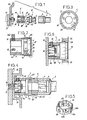
- Figure 1 est une vue partielle en coupe d'une première forme d'exécution de ce dispositif dont les différents éléments sont montrés en alignement avant montage sur l'écrou à protéger,
- Figure 2 est une vue en coupe longitudinale d'une autre forme d'exécution de l'adaptateur,
- Figure 3 est une vue de face en bout de l'extrémité antérieure de cet adaptateur,
- Figure 4 est une vue partielle en coupe longitudinale montrant l'adaptateur lorsqu'il est monté sur un écrou et au moment du vissage de ce dernier,
- Figure 5 est une vue en perspective montrant une forme d'exécution de la bague compensatrice pouvant être utilisée avec l'adaptateur ,
- Figure 6 est une vue de côté avec coupe partielle montrant l'adaptateur muni de la bague compensatrice.
- FIG. 1 is a partial sectional view of a first embodiment of this device, the various elements of which are shown in alignment before mounting on the nut to be protected,
- FIG. 2 is a view in longitudinal section of another embodiment of the adapter,
- Figure 3 is a front end view of the front end of this adapter,
- FIG. 4 is a partial view in longitudinal section showing the adapter when it is mounted on a nut and when it is screwed on,
- FIG. 5 is a perspective view showing an embodiment of the compensating ring which can be used with the adapter,
- Figure 6 is a side view with partial section showing the adapter provided with the compensating ring.
Comme montré à la figure 1, le dispositif selon l'invention est composé d'un adaptateur 1,d'un organe d'en- trainement intermédiaire 2 apte à coopérer avec une clé classique de serrage 3.De façon connue,l'organe d'entrai- nement intermédiaire 2 comporte une partie antérieure polygonale 4 apte à recevoir l'empreinte 5 de la clé 3 et,à son extrémité postérieure,des doigts longitudinaux 6 saillants de sa face diamétrale et aptes à coopérer avec des alésages 7 débouchant de la face antérieure 8 de l'adaptateur 1.As shown in Figure 1, the device according to the in vention is composed of an adapter 1, an intermediate drive member 2 able to cooperate with a
L'adaptateur est muni,dans sa partie postérieure, d'une empreinte intérieure 9,de section transversale polygonale et,notamment,hexagonale,apte à coiffer l'organe de liaison constitué par un écrou 10,dans la forme d'exécution représentéeoCet écrou 10 est vissé sur le goujon 12 saillant d'un moyeu 13 et traversant l'un des alésages 14 dont est munie la jante de roue 15.The adapter is provided, in its rear part, with an
L'adaptateur est également muni de moyens assurant sa liaison indémontable avec l'écrou 10,moyens qui,dans la forme d'exécution représentée,sont constitués par des vis de pression 16 vissés radialement dans des alésages taraudés 17 traversant radialement l'adaptateur,de manière à déboucher dans l'empreinte 9 et dans les parties de cette empreinte comportant des plats.Les vis 16 peuvent comporter des extrémités plates ou en cuvette,mais de préférence,elles comportent une extrémité conique.The adapter is also provided with means ensuring its non-removable connection with the
Comme montré à la figure 2,chacune de ces vis 16 est prolongée par une tête 16a,de type auto-cassante,c'est-à-dire susceptible d'être détachée du reste de la vis lorsque celle-ci est correctement positionnée et serrée avec un couple suffisant pour assurer la striction de la tête par rapport à son corps.Après détachement de la tête 16a, la vis 16 a une longueur au plus égale à celle du taraudage 17 correspondant.La liaison indémontable peut aussi être assurée soit,par engagement de force de pions coniques dans des alésages radiaux coniques,débouchant dans l'empreinte,et de manière que ces pions viennent en contact soit avec l'organe de fixation, par une ou plusieurs agrafes intercalées entre l'empreinte et l'organe de fixation,soit par soudure.As shown in FIG. 2, each of these
L'extrémité antérieure de l'adaptateur est munie d'une collerette 18 qui,saillant de sa face diamétrale 8,délimite un logement interne 21 dont la face périphérique constitue portée de centrage 19 pour une partie cylindrique 20 ménagée à l'extrémité postérieure de l'organe d'entraine- ment 2. Le diamètre de la portée 19 est égal,au jeu fonctionnel près,à celui de la partie 20 précitéeoThe front end of the adapter is provided with a
Cette portée cylindrique de l'organe 2 a une longueur sensiblement égale à la hauteur de la portée 19 de l'adaptateur l.Elle est raccordée au corps de l'organe d'en- trainement 2 par un épaulement 22 constituant indicateur de positionnement en coopérant avec le bord 23 de l'adaptateur 1.This cylindrical seat of the member 2 has a length substantially equal to the height of the
Pour empêcher le vol d'une roue de véhicule,un seul dispositif selon l'invention est mis en place sur l'un des organes de fixation de la roue au moyeu 13.Lorsque l'écrou 10,ou la tête de vis,est engagé dans l'empreinte 9 de l'adaptateur,les vis 16,au nombre de trois,sont vissées de manière que leurs pointes coniques pénètrent dans les faces correspondantes de l'organe de fixation.Lorsque le couple de serrage optimal est atteint,les têtes de vis 16a se cassent d'elles-mêmes.To prevent theft of a vehicle wheel, a single device according to the invention is put in place on one of the members for fixing the wheel to the hub 13.When the
Pour assurer la fixation de la roue,il suffit alors, comme montré à la figure 4 dans le cas d'une autre forme d'exécution,et après vissage manuel de l'écrou 10 avec l'adaptateur 1 sur le goujon 12,de parfaire le serrage au moyen de l'organe d'entrainement intermédiaire 2,lui-même entrainé par la clé de serrage 3.To ensure the fixing of the wheel, it then suffices, as shown in FIG. 4 in the case of another embodiment, and after manual screwing of the
Il est à noter que,lorsque l'organe d'entrainement intermédiaire 2 est engagé dans l'adaptateur,il est parfaitement positionné radialement par le centrage de sa partie cylindrique 20 dans la portée 19 de l'adaptateur et,longitudinalement,par butée de son épaulement 22 contre le bord 23 de la collerette 18.Pour éviter que,sous l'effet du couple de rotation important,les doigts 6 soient cisaillés ou déformés,l'opérateur doit vérifier l'engagement de ses doigts dans les alésages 7 correspondants de l'adaptateur en vérifiant que l'épaulement 22 vient bien en contact avec le bord 23 de la collerette 18.Il est évident que les mêmes précautions doivent être prises lors de l'opération de dévissage qui s'effectue exactement de la même façonoIt should be noted that, when the intermediate drive member 2 is engaged in the adapter, it is perfectly positioned radially by the centering of its
Avantageusement,et pour éviter que les vibrations consécutives aux déplacements du véhicule,tendent à dévisser les vis 16,celles-ci sont calées dans leur taraudage 17 par un joint-colle 31 interposé entre elles et ce taraudage et les rendant indémontables.Ce joint-colle est aussi interposé entre l'empreinte 9 et l'écrou 10 ou la tête de vis,de manière à compenser les jeux fonctionnels entre. ces deux pièces.Ce joint-colle répartit l'effort exercé, lors du montage et du démontage de la roue,sur l'ensemble adaptateur-écrou,c'est-à-dire évite que cet effort se répartisse uniquement sur les pieds des vis,mais au contraire,sur toutes les faces de l'écrou,malgré les variations de dimensions existant entre cet écrou et l'adaptateur.De plus,par son rôle anti-vibratoire,il s'oppose à ce que les vibrations de la roue se transmettent à l'adaptateur et favorisent le dévissage des viseAdvantageously, and to avoid that the vibrations consecutive to the movements of the vehicle, tend to unscrew the
Dans la forme d'exécution représentée à la figure 4, l'adaptateur 1 présente,dans sa partie postérieure,une partie cylindrique la dont la dimension extérieure correspond sensiblement à celle de la douille d'une clé de serrage traditionnelle,ce qui lui permet de s'engager sans difficulté dans les puits 24 réalisés dans la jante 15 pour loger les organes de fixation .Sa partie cylindrique la est raccordée à sa collerette 18 par une partie tronconique 1b. Cette partie tronconique améliore l'indémontabi- lité de l'adaptateur.En effet,de par sa forme,elle rend plus difficile son serrage par une pince à mâchoires parallèles,puisque,comme montré figure 6,ces mâchoires 32 ne viennent en contact avec elle que par deux points et non par une génératrice,comme c'est le cas avec un adaptateur cylindrique du type représenté à la figure 1.Cette partie tronconique 1b qui,dans la forme d'exécution représentée,a sa partie de plus grand diamètre près de l'extrémité antérieure,peut également présenter une conicité inverse.In the embodiment shown in Figure 4, the adapter 1 has, in its rear part, a cylindrical part the whose external dimension corresponds substantially to that of the socket of a traditional tightening wrench, which allows it to engage without difficulty in the
Avantageusement,de manière encore à éviter cette prise,l'adaptateur 1 est réalisé en acier et soumis à un traitement de cémentation,lui-même suivi d'un traitement de trempe par haute fréquence localisé sur la partie tronconique 1b,comme montré en 11 à la figure 2.Ainsi,la partie tronconique 1b présente une dureté de surface très importante s'opposant à toute prise,c'est-à-dire à toute pénétration des dents des mâchoires de tout outil classique tel que:pince-étau,clé serre-tube ou autres...De la sorte,de telles clés glissent sur la portée tronconique sans pouvoir prendre prise sur elle pour l'entrainer en rotation.De plus,l'absence de trempe à haute fréquence sur les autres parties de l'adaptateur permet à celles-ci de se déformer sans casser lorsqu'elles sont soumises à des chocs,ce qui rend pratiquement impossible l'entraine- ment en rotation de cet adaptateuroA antageusement v, still to avoid this socket, the adapter 1 is made from steel and subjected to a carburizing treatment, itself followed by a quenching treatment by high-frequency located on the tapered portion 1b, as shown at 11 in FIG. 2. Thus, the frustoconical part 1b has a very high surface hardness opposing any grip, that is to say any penetration of the teeth of the jaws of any conventional tool such as: pliers vice, pipe wrench or other ... In this way, such keys slide on the frustoconical bearing without being able to take hold of it to drive it in rotation. In addition, the absence of high frequency quenching on the others parts of the adapter allow them to deform without breaking when subjected to shocks, making it practically impossible to drive this adapter in rotation
Comme montré plus en détail aux figures 2 à 6,la collerette de l'adaptateur 18 est munie d'une gorge 25 pour l'encliquetage de la nervure 26 d'un capot 27 d'obturation du logement 21.Ce capot,qui constitue enjoliveur, empêche que de la boue et autres matières viennent obturer les alésages 7 nécessaires à l'entrainement en rotation de l'adaptateur 1 .As shown in more detail in FIGS. 2 to 6, the collar of the
Comme montré à la figure 3,et de façon connue,ces alésages 7 sont répartis irrégulièrement,tant angulaire- ment que radialement,afin d'éviter qu'ils puissent être entrainés par un organe d'entrainement intermédiaire 2 différent de celui qui leur correspond.As shown in FIG. 3, and in a known manner, these
Il ressort de ce qui précède que le dispositif selon l'invention est très efficace puisqu'il est inviolable sans recours à l'organe d'entrainement intermédiaire et qu'il permet de conserver l'organe de fixation de roue d'origine,ce qui rend pratiquement universelle son application .It appears from the above that the device according to the invention is very effective since it is inviolable without recourse to the intermediate drive member and that it makes it possible to keep the original wheel fixing member, this which makes its app practically universal cation.
Dans le but de réduire encore le nombre d'adaptateurs, c'est-à-dire d'assurer l'entrainement de tout type d'écrou à partir d'un seul type d'adaptateur ,1'empreinte 9 réalisée dans l'adaptateur peut correspondre à la plus grande dimension des écrous devant être entrainés et être associée,avant son montage sur l'organe de fixation correspondant,à une bague compensatrice 28 montrée figure 5. Cette bague,qui est hexagonale,a une épaisseur qui est sensiblement égale à la moitié de la différence entre les dimensions sur plat de l'empreinte 9 et de l'écrou correspondant .Ainsi,avec un jeu de bagues,il est possible de satisfaire à toutes les dimensions.Cette bague,réalisée par découpage et emboutissage,est ouverte en 28a. Cette ouverture facilite son introduction dans l'empreinte 9 de l'adaptateur 1 par rapprochement élastique de ses pans 28b qui reviennent ensuite automatiquement en position. Il est évident qu'elle peut être fermée.Elle présente,sur chacun de ses pans,des ouvertures 29 pour le passage des vis de fixation 16. Une telle bague peut également être utilisée entre l'empreinte 5 de la clé 3 et la partie hexagonale 4 de l'organe d'entrainement intermédiaire 2.In order to further reduce the number of adapters, that is to say to ensure the training of any type of nut from a single type of adapter, the
Il est évident que le dispositif,qui a été décrit dans le cas de son application aux organes de fixation de voitures,peut également être utilisé chaque fois qu'il est nécessaire de protéger contre le vol des assemblages de pièces réalisées par système vis-écrou.It is obvious that the device, which has been described in the case of its application to car fasteners, can also be used whenever it is necessary to protect against theft the assemblies of parts produced by screw-nut system. .
Claims (8)
Applications Claiming Priority (2)
| Application Number | Priority Date | Filing Date | Title |
|---|---|---|---|
| FR8114114 | 1981-07-15 | ||
| FR8114114A FR2509812B1 (en) | 1981-07-15 | 1981-07-15 | UNIVERSAL ANTI-THEFT DEVICE, PARTICULARLY FOR NUTS, SCREWS, BOLTS, APPLICABLE IN PARTICULAR TO FIXINGS OF VEHICLE WHEELS |
Publications (2)
| Publication Number | Publication Date |
|---|---|
| EP0070247A2 true EP0070247A2 (en) | 1983-01-19 |
| EP0070247A3 EP0070247A3 (en) | 1984-06-06 |
Family
ID=9260683
Family Applications (1)
| Application Number | Title | Priority Date | Filing Date |
|---|---|---|---|
| EP82420100A Withdrawn EP0070247A3 (en) | 1981-07-15 | 1982-07-13 | Universal anti-theft device, especially for nuts and bolts to fix car-wheels |
Country Status (3)
| Country | Link |
|---|---|
| EP (1) | EP0070247A3 (en) |
| JP (1) | JPS5817210A (en) |
| FR (1) | FR2509812B1 (en) |
Cited By (6)
| Publication number | Priority date | Publication date | Assignee | Title |
|---|---|---|---|---|
| GB2194827A (en) * | 1986-08-14 | 1988-03-16 | Leonard Albert Cooper | Driving formations of screws |
| FR2618497A1 (en) * | 1987-07-22 | 1989-01-27 | Henry Max | DEVICE FOR PREVENTING THE LOCKING OF A NUT, A SCREW OR A BOLT USED IN PARTICULAR AS A DEVICE FOR PROTECTION AGAINST THE THEFT OF A WHEEL OF A MOTOR VEHICLE |
| FR2658253A1 (en) * | 1990-02-13 | 1991-08-16 | Lanneree Daniel | LOCKING AND UNLOCKING ARRANGEMENT FOR A SCREW OR NUT DEVICE, PARTICULARLY FOR A SCREW OR ANTITHEFT NUT FOR VEHICLE WHEEL. |
| AU625662B2 (en) * | 1989-02-24 | 1992-07-16 | Pipe Couplings (Australasia) Pty. Limited | Tamper-proof valve arrangement |
| US5791848A (en) * | 1997-04-24 | 1998-08-11 | Mcgard, Inc. | Structure for converting standard drive fastener to security fastener |
| EP1002962A1 (en) * | 1998-11-19 | 2000-05-24 | France Telecom | Device for securing a fixing element |
Families Citing this family (2)
| Publication number | Priority date | Publication date | Assignee | Title |
|---|---|---|---|---|
| JPH0716095Y2 (en) * | 1990-11-30 | 1995-04-12 | 協永産業株式会社 | Fastener locking device for theft prevention of automobile parts etc. |
| US5628602A (en) * | 1996-01-18 | 1997-05-13 | Kyo-Ei Sangyo Kabushiki Kaisha | Anti-theft hub nut for vehicle wheels |
Citations (3)
| Publication number | Priority date | Publication date | Assignee | Title |
|---|---|---|---|---|
| GB1235897A (en) * | 1968-05-25 | 1971-06-16 | Audrey Mary Ramsden | A wheelnut cover |
| FR2359730A1 (en) * | 1976-07-26 | 1978-02-24 | Zeppellini Dino | Anti-theft nut for car wheel - has conical upper and lower part with specially shaped recesses requiring use of special spanner |
| GB2006371A (en) * | 1977-10-04 | 1979-05-02 | Hart H | Fastening means |
Family Cites Families (1)
| Publication number | Priority date | Publication date | Assignee | Title |
|---|---|---|---|---|
| GB1272215A (en) * | 1968-05-22 | 1972-04-26 | James Maxwell Craig | Improvements in bolt heads and nuts |
-
1981
- 1981-07-15 FR FR8114114A patent/FR2509812B1/en not_active Expired
-
1982
- 1982-07-13 EP EP82420100A patent/EP0070247A3/en not_active Withdrawn
- 1982-07-15 JP JP12226182A patent/JPS5817210A/en active Pending
Patent Citations (3)
| Publication number | Priority date | Publication date | Assignee | Title |
|---|---|---|---|---|
| GB1235897A (en) * | 1968-05-25 | 1971-06-16 | Audrey Mary Ramsden | A wheelnut cover |
| FR2359730A1 (en) * | 1976-07-26 | 1978-02-24 | Zeppellini Dino | Anti-theft nut for car wheel - has conical upper and lower part with specially shaped recesses requiring use of special spanner |
| GB2006371A (en) * | 1977-10-04 | 1979-05-02 | Hart H | Fastening means |
Cited By (10)
| Publication number | Priority date | Publication date | Assignee | Title |
|---|---|---|---|---|
| GB2194827A (en) * | 1986-08-14 | 1988-03-16 | Leonard Albert Cooper | Driving formations of screws |
| FR2618497A1 (en) * | 1987-07-22 | 1989-01-27 | Henry Max | DEVICE FOR PREVENTING THE LOCKING OF A NUT, A SCREW OR A BOLT USED IN PARTICULAR AS A DEVICE FOR PROTECTION AGAINST THE THEFT OF A WHEEL OF A MOTOR VEHICLE |
| EP0305231A1 (en) * | 1987-07-22 | 1989-03-01 | Wiener, Bernadette | Device to prevent the loosening of a nut, a screw or a bolt, to be used in particular as a protective device against the theft of a wheel of a motor vehicle |
| US4880344A (en) * | 1987-07-22 | 1989-11-14 | Max Henry | Device for preventing loosening of a member |
| AU625662B2 (en) * | 1989-02-24 | 1992-07-16 | Pipe Couplings (Australasia) Pty. Limited | Tamper-proof valve arrangement |
| FR2658253A1 (en) * | 1990-02-13 | 1991-08-16 | Lanneree Daniel | LOCKING AND UNLOCKING ARRANGEMENT FOR A SCREW OR NUT DEVICE, PARTICULARLY FOR A SCREW OR ANTITHEFT NUT FOR VEHICLE WHEEL. |
| WO1991012438A1 (en) * | 1990-02-13 | 1991-08-22 | Daniel Lanneree | Locking and unlocking arrangement for a screw or nut device, particularly a theft prevention screw or nut on a vehicle wheel |
| US5791848A (en) * | 1997-04-24 | 1998-08-11 | Mcgard, Inc. | Structure for converting standard drive fastener to security fastener |
| EP1002962A1 (en) * | 1998-11-19 | 2000-05-24 | France Telecom | Device for securing a fixing element |
| FR2786231A1 (en) * | 1998-11-19 | 2000-05-26 | France Telecom | SECURITY DEVICE FOR SOLIDARIZATION BODY |
Also Published As
| Publication number | Publication date |
|---|---|
| JPS5817210A (en) | 1983-02-01 |
| EP0070247A3 (en) | 1984-06-06 |
| FR2509812B1 (en) | 1985-11-29 |
| FR2509812A1 (en) | 1983-01-21 |
Similar Documents
| Publication | Publication Date | Title |
|---|---|---|
| FR2561327A1 (en) | AUTOSERREUR DEVILABLE NUT | |
| FR2815386A1 (en) | ANTI-LOCKING NUT DEVICE | |
| EP0070247A2 (en) | Universal anti-theft device, especially for nuts and bolts to fix car-wheels | |
| FR2513575A1 (en) | DRIVE WHEEL BEARING OF A MOTOR VEHICLE | |
| EP0305231B1 (en) | Device to prevent the loosening of a nut, a screw or a bolt, to be used in particular as a protective device against the theft of a wheel of a motor vehicle | |
| WO2009138627A1 (en) | Anti-theft fixing device for securing a wheel to the hub of a motor vehicle. | |
| FR2487455A1 (en) | DIFFICULTLY ALTERABLE THREADED FIXING DEVICE | |
| FR2930805A1 (en) | METHOD AND ARRANGEMENT FOR TIGHTENING A HARDWARE ELEMENT, FIXING AND CLAMPING DEVICE | |
| WO2003081057A1 (en) | Anti-theft device intended, in particular, for vehicle wheels | |
| US4353447A (en) | Cycle freewheel assembly and cycle wheel therefor | |
| EP3299650B1 (en) | A method for equiping the end of a thin walled tube with an axial stop that is adjustable by a threaded joint | |
| WO2015159034A2 (en) | Anti-theft fixing device for securing a wheel to the hub of a motor vehicle | |
| FR2919258A1 (en) | Motor vehicle's sub-assembly, has fixation device fixing instrument panel cross bar on front pillar, where cross bar and threaded unit of device have complementary reliefs blocking rotation of threaded unit relative to cross bar around axis | |
| WO2006037911A1 (en) | Device for fixing an anti-theft system, in particular for motor vehicle wheels | |
| WO1993000528A1 (en) | Live cable holding device | |
| EP0595952A1 (en) | Toothed fastener | |
| EP0002405B1 (en) | Device for positively locking a screw in a threaded bore | |
| FR2712845A1 (en) | Anti-theft device for securing nuts or bolts of e.g. motor vehicle wheels | |
| FR2499648A1 (en) | FIXING DEVICE FOR A GUIDE PIN OF A FLOATING CALIPER DISC BRAKE | |
| FR2857066A1 (en) | Antitheft screw mounting method for motor vehicle, has epoxy glue and brazing powder layer placed between screw head and hollow housing for connecting screw head and cap | |
| EP3819504B1 (en) | Anti-theft attachment device for securing a wheel to the hub of an automobile | |
| FR2573825A1 (en) | IMPROVED WHEEL NUT. | |
| FR2728318A1 (en) | Anti=theft screw or nut for mounting on motor vehicle wheels with specially coded key for its release | |
| FR2921704A1 (en) | Wheel hub and spindle assembly, has locking unit with central opening whose shape is adopted to cooperate with exterior shape of nut, where locking unit is force-mounted at interior of cylindrical cavity | |
| FR2998626A1 (en) | Self-locking safety nut for use with screw in e.g. land vehicle, has locking piece intended to move to position in which locking piece rests on screw, for locking nut on screw when nut is rotated in opposite direction of tightening of screw |
Legal Events
| Date | Code | Title | Description |
|---|---|---|---|
| PUAI | Public reference made under article 153(3) epc to a published international application that has entered the european phase |
Free format text: ORIGINAL CODE: 0009012 |
|
| AK | Designated contracting states |
Designated state(s): AT BE CH DE GB IT LI NL SE |
|
| PUAL | Search report despatched |
Free format text: ORIGINAL CODE: 0009013 |
|
| AK | Designated contracting states |
Designated state(s): AT BE CH DE GB IT LI NL SE |
|
| STAA | Information on the status of an ep patent application or granted ep patent |
Free format text: STATUS: THE APPLICATION IS DEEMED TO BE WITHDRAWN |
|
| 18D | Application deemed to be withdrawn |
Effective date: 19850131 |
|
| RIN1 | Information on inventor provided before grant (corrected) |
Inventor name: BRUN, JEAN |