EP0070110A2 - Imprimante sélective à jet d'encre - Google Patents
Imprimante sélective à jet d'encre Download PDFInfo
- Publication number
- EP0070110A2 EP0070110A2 EP82303265A EP82303265A EP0070110A2 EP 0070110 A2 EP0070110 A2 EP 0070110A2 EP 82303265 A EP82303265 A EP 82303265A EP 82303265 A EP82303265 A EP 82303265A EP 0070110 A2 EP0070110 A2 EP 0070110A2
- Authority
- EP
- European Patent Office
- Prior art keywords
- ink
- nozzle
- carriage
- container
- paper
- Prior art date
- Legal status (The legal status is an assumption and is not a legal conclusion. Google has not performed a legal analysis and makes no representation as to the accuracy of the status listed.)
- Granted
Links
Images


Classifications
-
- B—PERFORMING OPERATIONS; TRANSPORTING
- B41—PRINTING; LINING MACHINES; TYPEWRITERS; STAMPS
- B41J—TYPEWRITERS; SELECTIVE PRINTING MECHANISMS, i.e. MECHANISMS PRINTING OTHERWISE THAN FROM A FORME; CORRECTION OF TYPOGRAPHICAL ERRORS
- B41J2/00—Typewriters or selective printing mechanisms characterised by the printing or marking process for which they are designed
- B41J2/005—Typewriters or selective printing mechanisms characterised by the printing or marking process for which they are designed characterised by bringing liquid or particles selectively into contact with a printing material
- B41J2/01—Ink jet
- B41J2/015—Ink jet characterised by the jet generation process
- B41J2/04—Ink jet characterised by the jet generation process generating single droplets or particles on demand
- B41J2/06—Ink jet characterised by the jet generation process generating single droplets or particles on demand by electric or magnetic field
- B41J2/065—Ink jet characterised by the jet generation process generating single droplets or particles on demand by electric or magnetic field involving the preliminary making of ink protuberances
Definitions
- This invention relates to an ink-jet printing device, in which printing is carried out by inducing the selective emission of particles of an electrically conductive liquid ink through a nozzle from a container.
- printers are known in which a selective ink-jet is produced by pressure pulses induced piezoelectrically, or by electric pulses inducing electrostatic ejection of droplets. These printers are generally very complicated and costly because of problems in the rapid drying of the droplets. It has therefore been sought to produce emission of the ink in other ways in order to ensure good penetration of the ink and quick drying.
- the ink is contained in a conductive vessel of frusto-conical shape, of which the minor base, disposed upwards, is open for emission of the ink.
- the device comprises a point electrode which is disposed above the paper and is excited so as to cause the ink particles to be electrostatically attracted towards the electrode. This attraction is said to be favoured by a state of agitation of the surface of the liquid, and by its vaporisation caused by any electrical discharges created between the electrode and container.
- This method has various drawbacks, both because it is difficult to keep the ink at the level of the opening without marking the paper, and because of the difficulty producing consistent electrical discharges and the damage caused by them to the paper.
- a printing device has also been proposed in which the ink is kept at a predetermined level in a tube having its opening facing upwards. Two electrodes are inserted into the tube so that they are disposed in the same horizontal plane, and remain immersed under a predetermined depth of ink. Ink emission is produced by instantaneous vaporisation of a portion of ink inside the nozzle at the level of the electrodes, so as to hurl the overlying layer of ink against the paper.
- the ink is electrically nonconductive, and instantaneous vaporisation is produced by a breakdown in the dielectric properties of the ink, this inducing a spark between the electrodes.
- the ink is electrically conductive with a high electrical resistance, and is preheated to a temperature slightly lower than its boiling point.
- current passes through the ink to produce instantaneous heat which vaporises a portion of ink, so expelling the overlying ink.
- a printing device has also been proposed (FR 2 092 577) in which the tube has a horizontal axis, and is connected to the bottom of a container of electrically non-conductive ink. Coaxially to the tube there is disposed an electrode in the form of a pointed needle, while into the free end of the tube there is inserted a metal sleeve which reduces the tube diameter and forms the second electrode. Because of its pressure, the ink normally fills the electrode, so that both the electrodes are immersed. On exciting the two electrodes, a spark is struck in the liquid between the two electrodes due to breakdown of the dielectric, and causes instantaneous vaporisation of parts of the ink between the electrodes, with the expulsion through the sleeve of the ink contained therein.
- This device has the drawback that because of the ink pressure, particularly after relatively long intervals of inactivity, the ink tends to leak from the sleeve, whereas the spark passing through the ink causes undesirable physical-chemical transformations.
- a printing device has been proposed (GB 2 007 162) in which in order to emit an ink droplet from a nozzle, an ink vapour bubble is created inside a nozzle by means of an electrothermal transducer disposed outside the nozzle.
- This device generates a large quantity of heat which has to be quickly eliminated in order to ensure repeatability of the phenomenon.
- only one droplet is generated each time, so that it has the same drawbacks as devices in which the ink jet is generated by piezoelectric or electrostatic means.
- the object of the present invention is to provide a selective ink-jet printing device which prevents deterioration of the ink, and which ensures the printing of indelible marks which are immediately dried.
- an ink-jet printing head 15 is disposed in front of a print support, for example a sheet of paper 14.
- the head 15 is constituted by a block 16 of insulating material, for example a polycarbonate or polyphenylene oxide resin, in which there are provided two parallel, laterally spaced ducts or bores 17 and 18 ( Figures 2 and 4) disposed in the same horizontal plane.
- the two bores 17 and 18 open into an oblong compartment 19 which constitutes a small capacity container for the ink 20.
- the two bores 17 and 18 have counterbores 21 and 22 into which two metal tubes 23 and 24 having an inner diameter not less than that of the bores 17 and 18 are fixed, being for example cemented or heat fused.
- the tubes 23 and 24 are of stainless steel or other metal resistant to corrosion by the ink 20 and by the galvanic action of the current in the ink.
- the tube 26 is connected to a vessel 28 in which there is disposed a quantity of ink 20 much greater than that which can be held in the container 19.
- the conduit 26 always dips into the ink 20 in the vessel 28.
- the conduit 27 is connected to a suction pump 30 which returns in indrawn ink into the vessel 28, above the ink level, so as to ensure a head for the pump 30 independent of the ink level. Consequently the ink is circulated through the container 19, the ink entering through the bore 17 and leaving through the bore 18.
- the container 19 is closed by a plate 31 which is fused on to the block 16 and has a thickness of the same order of magnitude as the depth of the container 19.
- a nozzle 36 constituted by a capillary bore of very small diameter, for example a few hundredths of a millimetre, so as to ensure capillary effects on the ink 20.
- the nozzle 36 can have a shape which is either cylindrical or slightly convergent, for example conical ( Figure 3).
- the plate 31 may be an insulating layer of alumina or other refractory or vitreous ceramic material.
- the thickness of the plate 31 is about 0.6 mm, while the depth of the container 19 is of the same order of magnitude as the thickness of the plate 31, for example about 0.4 mm.
- the nozzle 36 can be made by boring the plate 31 before fixing it on the block 16, using a laser beam directed on to that surface which is to remain inside the head 15, so that the nozzle 36 becomes substantially conical in shape from the inside outwards.
- the diameter of the outer aperture of the nozzle 36 is about 35 ⁇ , while the diameter of the inner aperture is about 120 ⁇ .
- the exit diameter of the nozzle can vary from 20 to 100 ⁇ according to the fluidity of the chosen ink and the required size of the dot to be printed by the ink.
- the thickness of the plate 31, and thus the length of the nozzle 36 can vary from a minimum of 0.2 mm to a maximum of 1 mm, while the depth of the container 19 can be greater than that indication up to a maximum of double the length of the nozzle 36.
- the sections normal to the depth of the container have a linear dimension up to two orders of magnitude relative to the depth.
- the two ducts 17 and 18 are disposed so that they emerge from the container 19 in the same horizontal plane, and are equidistant from the nozzle 36 (see also Figure 4).
- a circular electrode 37 concentric with the nozzle 36 is deposited on the plate 31 by the silk-screen method.
- the circular electrode 37 is formed from a layer of erosion-resistant metal such as nickel grown galvanically, and a lyer of non-oxidisable conducting metal of high melting point such as platinum.
- the thickness of the electrode 37 is of the order of 50 J . 1 , while its inner diameter can vary from a minimum equal to the outer diameter of the nozzle 36 (as indicated at 37' in Fig 3) to a maximum of 1 mm.
- a diameter of 0.4 mm has been chosen in order to provide a relatively large free surface towards the nozzle 36, to supply the energy required for the jet and obtain good wear resistance.
- the outer surface of the plate 31 is disposed at a distance from the paper 14 of between 0.1 and 2 mm. Preferably, this distance is kept at 0.2 mm ( Figures 1 and 2).
- the electrode 37 has a downwardly extending tongue 38, which is connected by a conductor 39 to the positive pole of a pulse generator 41.
- a second conductor 40 is soldered at one end to the metal tube 23 and is connected at the other end to earth, so that the tube 23 constitutes a second electrode in contact with the ink 20.
- the ink 20 is constituted by a solution of dyes in an electrically conducting liquid carrier having a relatively low specific resistance.
- a saline electrolyte can be added to the solution.
- the electrolyte can consist of a chloride or sulphate of lithium, magnesium or potassium.
- the dye can be of acid, solvent or direct type in a quantity of 2.5-6%.
- This dye can consist of a nigrosine supplied by the firm Bayer.
- the kinematic viscosity of the ink should be low, preferably between 1 and 1.5 centistokes, in order to facilitate circulation of the ink 20 through the tubes 23, 24, 26 and 27, to facilitate its penetration into the nozzle 36 and to reduce the energy necessary for generating the printing jet.
- the pump 30 is kept in operation in order to keep the ink 20 circulating through the container 19.
- the pressure in the container is slightly negative, for example by an amount between 0.005 and 0.05 kg/em 2 but not so low as to prevent the ink 20 from invading the nozzle 36 by capillarity.
- the ink 20 then forms a concave meniscus 42 ( Figure 3) substantially in line with the exit aperture of the nozzle 36.
- the pulse generator 41 On activating the pulse generator 41 ( Figure 1), it generates at the electrode 37 a voltage pulse, described in greater detail hereinafter, thus supplying a quantity of energy indicated by the area beneath the curve W in Figure 5, in which the ordinate indicates the power values in kW.
- This voltage causes a sudden increase in the ionisation of the space lying between the electrode 37 and the meniscus 42 which is at the same potential as the electrode 23, so causing a passage of electric current of ionic type.
- residues 43 Figure 6a of the ink 30 between the electrode 37 and the edge of the nozzle 36, the voltage induces a current of resistive type in the ink 20.
- the vaporisation of the layer 46 increases the resistance in the nozzle, so that the current through the electrode 37 ceases substantially as soon as the spray 48 separates from the nozzle 36.
- the ink particles then proceed exclusively by the effect of the inertia and the pressure generated locally by the vaporisation.
- This spray 48 is hurled towards the paper 14 at a high speed of the order of 40-50 m/sec.
- curve A indicates the movement of the ink particles in tenths of a millimetre as a function of time starting from their emergence from the exit aperture of the nozzle 36, this being indicated on the ordinate axis at O on the diagram.
- the time in ⁇ sec is indicated starting from the beginning of the spray, as the duration of the power pulse W can vary.
- Figure 5 shows the nozzle 36 and the paper 14 on the same scale as the ordinate axis, from which it can be seen that the spray 48 ( Figure 6d) reaches the paper 14 before having excessively widened out, to deposit on the paper a rose pattern of ink particles, which print a dot having a diameter of between 0.1 and 0.3 mm.
- the sudden vaporisation of the layer 46 (Figure 6b) of ink causes a withdrawal of the meniscus 42, indicated by the curve R of Figure 5, and which at its lowest point is substantially of the same order as the length of the nozzle 36, so that gas bubbles 49 ( Figure 4) of a diameter of 0.1 - 0.2 mm are created where the nozzle 36 joins on to the container 19, and these must be evacuated.
- This is done by circulating the ink 20 by the pump 30, so that the bubbles 49 become concentrated towards the discharge bore 18 as shown in Figure 4. It has been found experimentally that a throughput of the pump 30 of the order of 1 cm 3 per minute is sufficient for the timely evacuation of the bubbles 49 and to maintain the aforesaid negative pressure at the nozzle 36.
- the pressure wave caused by the vaporisation of the ink layer 46 is propagated through the ink 20 in the container 19 and reflected back to push the meniscus 42 towards the outside of the nozzle 36 at a continually increasing speed (the rising part of the line R in Figure 5).
- a second spray 50 ( Figure 6e) of ink 20 leaves the nozzle 36 in the form of a dart at a speed of the order of 50-100 m/sec, i.e. greater than that of the first spray 48.
- the movement of this dart is represented by the curve D in Figure 5.
- the ink particles 50' (Figure 6f) which are formed by the dart 5 0 now move along approximately parallel trajectories, so that, assuming the paper 14 to be at rest, a second set of particles 50' becomes deposited in the central zone of the printed dot to make the dot more uniform and improve penetration of the ink 20 into the paper 14.
- the dart 50 emerges for a few microseconds, as indicated in Figure 5 by the hatched zone to the right of curve D.
- the dart 50 strikes the rows of ink particles of the dot deposited by the first spray 48 in a position offset from the centre. However, the speeds are such that this position is still within the area of the dot, so that no appreciable smear occurs. After the separation of the dart 50 from the nozzle 36, the meniscus 42 returns to its initial position of Figure 6a.
- the next pulse generated by the pulse generator 41 should not be generated before the dart 50 separates from the nozzle 36, so that the optimum printing frequency should not exceed the maximum frequency at which there is no overlapping of the curves R in Figure 5.
- This frequency is of the order of 1300 Hz with the experimented head 15.
- a slight overlap of the successive curves R does not produce appreciable effects on the printed dots, as the only effect is that part of the dart 50 becomes involved in the next excitation of the electrode 37, so that the printing frequency can even exceed the said value.
- a first control circuit 41 for the printing head 15 will now be described in detail with reference to Figure 7.
- the electrical circuit of the head 15 can be represented by a resistor 101 and a capacitor 102 connected in parallel with each other between the two conductors 39 and 40 of the head 15.
- the control circuit comprises a step-up transformer 103, of which the primary 104 is connected to an energy source 106 and to a driver circuit 107.
- the secondary 108 of the transformer 103 is connected to the conductors 39 and 40 and has its own parasitic capacitance 109, the effect of which will be seen hereinafter.
- the energy source*..106 is supplied by a positive voltage, for example 50 V, charging a shunt capacitor 110 in order to provide a high instantaneous current intensity.
- the driver circuit 107 comprises a logic signal amplifier 111 connected to the base of a power t ranistor 112 in parallel with a diode 113, which enables the excess energy to be returned to the power unit.
- a diode 114 in series with a zener diode 116 are connected in parallel with the primary l04 of the transformer 103. Normally the transistor l12 is cut off, so that no current passes through the primary 104.
- the amplifier 111 ( Figure 7) makes the transistor 112 conducting for an equal time, so generating in the primary 104 a rapidly increasing current C ( Figure 8) which creases suddenly as soon as the logic signal L ceases.
- a voltage V 2 ( Figure 8) is then generated in the secondary 108 ( Figure 7) and thus between the electrodes 37 and 23 of the head 14, and this increases rapidly as long as the current C lasts in the primary 104. Because of the above- described phenomena between the electrode 37 ( Figure 3) and the ink 20 in the nozzle 36, this voltage generates in the head 15 between the electrodd 37 and electrode 23 a current C t ( Figure 8) which firstly increases as long as the control pulse lasts.
- the component values of the control circuit 41 are such that the voltage V s reaches about 3000 V, while the current C p reaches a value of about 10 A.
- the voltage V s decreases rapidly to a value of about 1000 V, whereas the current C p decreases to zero after about 15 ⁇ sec from the beginning of the logic signal.
- the first ink spray 48 is generated substantially at that moment, as seen with reference to Figures 5 and 6.
- the voltage V s is the secondary 108 decreases more slowly, and because of its parasitic capacitance 109 and the magnetisation inductance inverts its polarity.
- the return to zero of the voltage V s in the secondary takes place after a delay which depends on the value of the negative voltage thus obtained.
- This voltage is limited by the setting of the zener 116 so as not to create negative effects on the rhythm of the meniscus 42.
- the negative voltage reaches a value of about 1200 V and returns to zero after about 100 ⁇ sec, i.e. when the second spray 50 has completely ceased and the meniscus 42 has returned to rest.
- the printing control can be carried out with a maximum frequency of about 10,000 H z, the limit of which is given substantially by the control circuit 41.
- FIG 9 shows a further embodiment of the control circuit 41, in which those circuit elements analogous to those of Figure 7 are represented by the same numeral plus a prime, and will therefore not be further described.
- This circuit known as an indirect energy transfer circuit, makes use of a predetermined air gap in the magnetic circuit of the two windings 104' and 108', so that the transformer 109' behaves as an inductance.
- the cycle of the electrical circuit has a duration less than the time which it takes the meniscus 42 to return to rest.
- the next logic signal L' can be generated before the meniscus 42 returns to rest, for example after about 60 ⁇ sec from the first, so that the transistor 112' is cut off when the meniscus 42 reaches the exit aperture of the nozzle 36.
- the frequency of the jet can be increases up to 15,000 Hz without superimposing the second energisation of the circuit 41 on the emergence of the dart 50 ( Figure 6e) , thus considerably increasing the printing speed. This is particularly useful in the case of high definition printing, in which is required to be as continuous as possible and the dot diameter reduced to a minimum.
- the ink consumption of the printing device according to the invention is much less than that of analogous selective ink-jet printing devices of the piezoelectric type. It has been found experimentally that the mass of ink sprayed in order to print a dot of minimum diameter 150 ⁇ by means of a nozzle operating piezoelectrically is of the order of 0 .3 x 10 -6 g, represented by a single droplet. In order to print a dot of the same diameter using the device of the invention, a mass of ink is sprayed of the order of 0.4 x 10 -7 g, represented by some tens of droplets, of which the diameter is therefore substantially less than the droplet obtained piezoelectrically.
- the thickness of the ink in the second case is on the averate 1/8 that of the first case, so that is is apparent that the print dries more quickly. Complicated drying devices are therefore not required, and marks or smears do not arise even if the printed sheet is touched immediately after printing.
- the negative electrode 23 can be constituted by a second conductive layer prepared by silk-screen printing on the inner surface of the plate 31, with an appendix on theoutside of the head for its electrical connection to the negative of the generator 41 or to earth.
- the polarity of the electrodes can also be reversed.
- the electrode 23 can reach substantially in line with the outer edge of the nozzle 36, as indicated by dashed lines and by the numeral 37' in Figure 3.
- the current between the electrode 37' and ink 20 is mainly of resistive or electrolytic type.
- the cross-section of the nozzle 36 of smallest diameter again lies in a position corresponding with the outer surface of the plate 31.
- the ink is again vaporised at this cross-section, and causes an agitation of the meniscus 42, so that after the first excitation of the electrode 37', the two previously described sprays 48 and 50 are generated regularly.
- various nozzles 36 can be provided in a single head 15, in order to increase the printing speed.
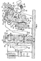
- a printing device using the head 15 heretofore described is illustrated in Figures 11 and 12.
- the device can be used in a typewriter, teleprinter, computer terminal or as a printer at the output of a data processing system or as a printer in a facsimile transmission system.
- the characters are printed in dot matrices.
- the head 15 comprises only a single nozzle 36, the head 15 is moved rapidly with reciprocating motion over the entire length of the print line, and the paper 14 is advanced vertically each time through a distance corresponding to the distance between two rows of the matrix.
- the printing device is provided with a carriage 51 (Figure 11) guided transversely on a bar 52 fixed to the fixed frame 53 of the printing device.
- the carriage 51 is also provided with two forks 54 ( Figure 12) which very slackly engage a transverse bar 55.
- the left hand end of the bar 55 is mounted on the corresponding side of the frame 53 in such a manner as to allow a certain movement of the left hand end of the bar 55.
- This latter end is connected to the relative side of the frame 53 by a spring 56, and can be moved from one to the other of two positions of a positioning slot 57 (Figure 11) in the right hand side, in order to facilitate insertion of the paper 14.
- the carriage 51 also carries a leaf spring 58 which cooperates with the bar 55 in order to urge the carriage 51 elastically in a clockwise direction about the bar 52, as will be more apparent hereinafter.
- the carriage 51 is connected to the two ends 59 and 60 ( Figure 12) of a flexible cable 61 which winds at one end about a guide pulley 62, and at the other end, by means of a few turns of the cable 61, about a drive pulley 63.
- This latter is fixed on a shaft 64, on which there is also fixed a gear wheel 66.
- This is constantly engaged with a pinion 67 fixed on to the shaft 68 of a reversible electric motor 69.
- the disc 70 On the other end of the shaft 68 ( Figure 11) there is fixed a stroboscopic disc 70, which cooperates with a transducer 71 in order to indicate the transverse position of the head 15 at any time.
- the disc 70 comprises a set of slots 72 ( Figure 12) arranged to be read by the transducer 71.
- the transmission ratio between the motor 69 and carriage 51 is such that the pitch of the slots 72 corresponds to a transverse movement of the carriage 51 of 0 .2 mm.
- the disc 70 is divided into four sectors, each of 9 0 o and alternately defined by a portion 73 of greater diameter which is also arranged to be sensed by the transducer 71. Eight slots are disposed in each sector, so that the signal given at the beginning and end of each portion 73 constitutes the character initiation signal.
- the paper sheet 14 ( Figure 11) is guided by a rotatable platen 74, with which there cooperate two sets of front paper pressing rollers 75 and one set of rear paper pressing rollers 76.
- the front rollers 75 are mounted rotatably in groups of four (two upper and two lower) on a block 77 having two lugs 78 guided in two corresponding slots 79 in a fixed transverse bar 80 of C cross-section.
- a compression spring 81 disposed between the bar 80 and each block 77 keeps the corresponding four rollers 75 resting against the platen 74.
- a helical gear wheel 82 is fixed on to the platen 74 and engages with a worm 83 fixed on the shaft of a stepping motor 84.
- the platen 74 is rotated at each reversal of the motion of the carriage 51 by the motor 84, worm 83 and helical gear wheel 82,.so as to cause the paper to advance through 0.2 mm.
- the paper 14 rests on a support bar 85 which is slightly inclined in order to improve print visibility.
- the carriage 51 is provided with a nose which rests against the paper 14 on the bar 85 so that the nozzle spacing is independent of the thickness of the paper 14.
- the carriage 51 also comprises a surface 87 perpendicular to the support plane of the paper sheet 14 on the bar 85.
- the head 15 is removably fixed to the surface 87 of the carriage 51 so that the the plate 31 is at the required distance from the paper 14.
- the block 16 of the head 15 is provided with two brackets 88 ( Figure 2), each comprising a slot 89, and is removably fixed to the carraige 51 by means of two screws 90 ( Figure 11).
- the carriage 51 ( Figure 11) is of a metal material, and is electrically connected to the conductor 40 ( Figure 2) of the tube 23 by way of a metal ring 91 fixed to the conductor 40 and mounted as a washer for one of the two screws 90, so that the negative electrode 23 of the head 15 is connected to earth.
- the conductor 39 ( Figure 1) connected to the positive electrodd 37 is connected to the pulse generator 41, and is sufficiently long and flexible to enable the head 15 to move transversely.
- the pump 30 On the fixed frame 53 is mounted the pump 30, which comprises a plate 92 on which a motor-reduction gear unit 93 is mounted.
- a disc 95 (Figure 11) is fixed on the shaft 94 of the geared motor 93.
- Six rotatable rollers 96 are mounted on the disc 95 concentrically to the shaft 94, and on the plate 92 there is fixed a cylindrical cam 97 ( Figure 12) which is disposed eccentrically to the shaft 94 and has its minimum distance from the shaft 94 at the lower zone 98.
- a tube 100 is inserted between the cam 97 and rollers 96, so that each time a roller 96 passes through the zone 97, a compression of the tube 100 is generated, so that the pump 30 is known as a peristaltic pump.
- the end of the tube 27 is inserted into one end of the tube 100.
- the tube 100 has substantially the same inner diameter as the tube 27, but a much greater thickness in order to resist the pumping effect of the rollers 96. It is therefore apparent that for each compression of the tube 100 there is a suction effect in the container 19 of the head 15.
- the disc 95 is rotated at a speed of sixteen revolutions per minute, so that the suction pulsations occur at a frequency of 96 per minute.
- the ink vessel 28 is disposed on the fixed frame 53 of the printing device, and can for example have a capacity of from 3 to 5 cm 3 , this enabling from 300 to 500 pages of type to be printed.
- the vessel 28 has a screw cap 99 through which the end of the tube 100 passes sufficiently slackly to ensure that the ink leaving the pump 30 is at atmospheric pressure.
- the tube 100 terminates above the level of the ink, and the tube 26 connects the tube 23 of the head 15 to the vessel 28 below the level of the ink 29.
- the vessel 28 can be "refilled by unscrewing the cap 99.
- the tubes 26 and 27 are of sufficient length and flexibility to allow transverse movement of the head 15.
- Alphanumerical characters are printed in accordance with a matrix of partially superimposed dots.
- the characters are generated by means of a character generator constituted by a decoder arranged to provide a set of signals representing the complete arrangement of the dots to be written, for each input character code.
- the signals of the various characters are arranged in a buffer in known manner, so as to print both during the outward stroke and during the return stroke of the head.
- the bar 85 can be dispensed with, and printing can be carried out directly on the platen.
- the transverse movement of the carriage can be of variable extent according to printing requirements, and can be attained by different means, for example by means of an eccentric.
- the head 15 can be mounted with a different inclination or an inclination which is opposite to that indicated.
Applications Claiming Priority (2)
| Application Number | Priority Date | Filing Date | Title |
|---|---|---|---|
| IT6795981 | 1981-07-10 | ||
| IT67959/81A IT1144294B (it) | 1981-07-10 | 1981-07-10 | Dispositivo di stampa getto selettivo d inchiostro |
Publications (3)
| Publication Number | Publication Date |
|---|---|
| EP0070110A2 true EP0070110A2 (fr) | 1983-01-19 |
| EP0070110A3 EP0070110A3 (en) | 1984-04-25 |
| EP0070110B1 EP0070110B1 (fr) | 1987-03-04 |
Family
ID=11306723
Family Applications (1)
| Application Number | Title | Priority Date | Filing Date |
|---|---|---|---|
| EP82303265A Expired EP0070110B1 (fr) | 1981-07-10 | 1982-06-23 | Imprimante sélective à jet d'encre |
Country Status (5)
| Country | Link |
|---|---|
| US (1) | US4502054A (fr) |
| EP (1) | EP0070110B1 (fr) |
| JP (1) | JPS5836462A (fr) |
| DE (1) | DE3275516D1 (fr) |
| IT (1) | IT1144294B (fr) |
Cited By (5)
| Publication number | Priority date | Publication date | Assignee | Title |
|---|---|---|---|---|
| EP0129330A2 (fr) * | 1983-06-10 | 1984-12-27 | Ing. C. Olivetti & C., S.p.A. | Tête d'impression par projection d'encre |
| EP0133167A2 (fr) * | 1983-07-20 | 1985-02-13 | Ing. C. Olivetti & C., S.p.A. | Imprimante par projection d'encre, en particulier pour l'impression à grande vitesse |
| EP0159188A2 (fr) * | 1984-04-16 | 1985-10-23 | Dataproducts Corporation | Méthode de commande d'un dispositif à jet d'encre pour obtenir une impression à haute résolution |
| EP0128679B1 (fr) * | 1983-06-10 | 1988-07-27 | Ing. C. Olivetti & C., S.p.A. | Tête d'impression à jet d'encre |
| KR101250854B1 (ko) * | 2004-09-17 | 2013-04-04 | 에머슨 일렉트릭 컴파니 | 코리올리 유량계에 대한 보정 방법 및 장치 |
Families Citing this family (22)
| Publication number | Priority date | Publication date | Assignee | Title |
|---|---|---|---|---|
| US4554558A (en) * | 1983-05-19 | 1985-11-19 | The Mead Corporation | Fluid jet print head |
| IT1195146B (it) * | 1986-09-01 | 1988-10-12 | Olivetti & Co Spa | Inchiostro particolarmente adatto per una stampante a getto d inchiostro |
| IT1195151B (it) * | 1986-09-05 | 1988-10-12 | Olivetti & Co Spa | Apparecchiatura per ripristinare il funzionamento degli ugelli di una testina di stampa a getto d inchiostro e relativo procedimento |
| US4692776A (en) * | 1986-09-15 | 1987-09-08 | Polaroid Corporation | Drop dispensing device and method for its manufacture |
| US5189437A (en) * | 1987-09-19 | 1993-02-23 | Xaar Limited | Manufacture of nozzles for ink jet printers |
| JPH023312A (ja) * | 1988-06-20 | 1990-01-08 | Canon Inc | インクジェット記録方法 |
| CH677755A5 (fr) * | 1988-10-05 | 1991-06-28 | Battelle Memorial Institute | |
| GB8912245D0 (en) * | 1989-05-26 | 1989-07-12 | Pa Consulting Services | Liquid jet recording process |
| JP3008609B2 (ja) * | 1991-11-13 | 2000-02-14 | 松下電器産業株式会社 | インク吐出装置 |
| KR100249292B1 (ko) * | 1991-12-18 | 2000-03-15 | 줄리 엠. 알스턴 | 입상물질의 이산응집물 제조방법 및 그 장치 |
| US5221934A (en) * | 1992-04-01 | 1993-06-22 | Eastman Kodak Company | Electrochemical resistive ink jet head |
| DE69306295T2 (de) * | 1992-04-24 | 1997-04-03 | Hewlett Packard Co | Regelung des Gegendrucks beim Farbstrahldrucken |
| CA2166419C (fr) * | 1993-07-01 | 2004-11-23 | Stephen Nicholls | Encre liquide pour appareil d'impression a jet d'encre |
| US5473354A (en) * | 1994-05-26 | 1995-12-05 | Hewlett-Packard Company | Ink-delivery apparatus |
| US5936650A (en) * | 1995-05-24 | 1999-08-10 | Hewlett Packard Company | Ink delivery system for ink-jet pens |
| KR100205747B1 (ko) * | 1996-07-04 | 1999-07-01 | 윤종용 | 잉크젯프린터의 분사장치 및 분사방법 |
| KR100189159B1 (ko) * | 1996-07-24 | 1999-06-01 | 윤종용 | 잉크젯 프린터의 분사장치 및 분사방법 |
| US7275812B2 (en) * | 2003-01-29 | 2007-10-02 | Fujifilm Corporation | Ink jet head and recording apparatus using the same |
| US7510274B2 (en) * | 2005-01-21 | 2009-03-31 | Hewlett-Packard Development Company, L.P. | Ink delivery system and methods for improved printing |
| US8263414B2 (en) * | 2005-05-23 | 2012-09-11 | Siemens Healthcare Diagnostics Inc. | Dispensing of a diagnostic liquid onto a diagnostic reagent |
| DE102006001223A1 (de) * | 2006-01-10 | 2007-07-12 | Khs Ag | Vorrichtung zum Bedrucken von Flaschen oder dergleichen Behälter |
| EP2605910B1 (fr) * | 2010-08-19 | 2020-10-21 | Hewlett-Packard Development Company, L.P. | Ensemble tête d'impression à jet d'encre à groupement large comportant un écran |
Citations (5)
| Publication number | Priority date | Publication date | Assignee | Title |
|---|---|---|---|---|
| US3179042A (en) * | 1962-06-28 | 1965-04-20 | Sperry Rand Corp | Sudden steam printer |
| US3750564A (en) * | 1971-02-05 | 1973-08-07 | Olympia Werke Ag | Electrostatic capillary apparatus for producing an imprint |
| FR2256034A1 (en) * | 1973-12-28 | 1975-07-25 | Xerox Corp | On demand type data ink printer(spitter) - avoids escape or dripping of ink from coated capillary tubes |
| US4238807A (en) * | 1977-12-28 | 1980-12-09 | Ing. C. Olivetti & C., S.P.A. | Non-impact printing device |
| FR2493226A1 (fr) * | 1980-10-31 | 1982-05-07 | Olivetti & Co Spa | Dispositif d'impression a jet selectif d'encre et tete d'impression utilisant ledit dispositif |
Family Cites Families (8)
| Publication number | Priority date | Publication date | Assignee | Title |
|---|---|---|---|---|
| US2978088A (en) * | 1958-09-12 | 1961-04-04 | Ibm | Paper feeding device |
| US3705043A (en) * | 1970-12-07 | 1972-12-05 | Dick Co Ab | Infrared absorptive jet printing ink composition |
| US3974508A (en) * | 1974-12-16 | 1976-08-10 | Gould Inc. | Air purging system for a pulsed droplet ejecting system |
| JPS594310B2 (ja) * | 1979-06-30 | 1984-01-28 | 株式会社リコー | インクジェット記録装置 |
| US4359744A (en) * | 1980-11-03 | 1982-11-16 | Exxon Research And Engineering Co. | Ink jet printer with peristaltic pump |
| US4343012A (en) * | 1980-12-30 | 1982-08-03 | International Business Machines Corporation | Printer control circuit |
| DE3269768D1 (en) * | 1981-01-21 | 1986-04-17 | Matsushita Electric Ind Co Ltd | Ink jet printing head utilizing pressure and potential gradients |
| US4364054A (en) * | 1981-03-02 | 1982-12-14 | Exxon Research And Engineering Co. | Method and apparatus for fluid jet printing |
-
1981
- 1981-07-10 IT IT67959/81A patent/IT1144294B/it active
-
1982
- 1982-06-23 DE DE8282303265T patent/DE3275516D1/de not_active Expired
- 1982-06-23 EP EP82303265A patent/EP0070110B1/fr not_active Expired
- 1982-06-28 US US06/392,664 patent/US4502054A/en not_active Expired - Fee Related
- 1982-07-07 JP JP57118314A patent/JPS5836462A/ja active Granted
Patent Citations (5)
| Publication number | Priority date | Publication date | Assignee | Title |
|---|---|---|---|---|
| US3179042A (en) * | 1962-06-28 | 1965-04-20 | Sperry Rand Corp | Sudden steam printer |
| US3750564A (en) * | 1971-02-05 | 1973-08-07 | Olympia Werke Ag | Electrostatic capillary apparatus for producing an imprint |
| FR2256034A1 (en) * | 1973-12-28 | 1975-07-25 | Xerox Corp | On demand type data ink printer(spitter) - avoids escape or dripping of ink from coated capillary tubes |
| US4238807A (en) * | 1977-12-28 | 1980-12-09 | Ing. C. Olivetti & C., S.P.A. | Non-impact printing device |
| FR2493226A1 (fr) * | 1980-10-31 | 1982-05-07 | Olivetti & Co Spa | Dispositif d'impression a jet selectif d'encre et tete d'impression utilisant ledit dispositif |
Cited By (8)
| Publication number | Priority date | Publication date | Assignee | Title |
|---|---|---|---|---|
| EP0129330A2 (fr) * | 1983-06-10 | 1984-12-27 | Ing. C. Olivetti & C., S.p.A. | Tête d'impression par projection d'encre |
| EP0129330A3 (en) * | 1983-06-10 | 1986-06-04 | Ing. C. Olivetti & C., S.P.A. | Ink jet print head |
| EP0128679B1 (fr) * | 1983-06-10 | 1988-07-27 | Ing. C. Olivetti & C., S.p.A. | Tête d'impression à jet d'encre |
| EP0133167A2 (fr) * | 1983-07-20 | 1985-02-13 | Ing. C. Olivetti & C., S.p.A. | Imprimante par projection d'encre, en particulier pour l'impression à grande vitesse |
| EP0133167A3 (en) * | 1983-07-20 | 1986-01-22 | Ing. C. Olivetti & C., S.P.A. | Ink jet printer, particularly for high speed printing |
| EP0159188A2 (fr) * | 1984-04-16 | 1985-10-23 | Dataproducts Corporation | Méthode de commande d'un dispositif à jet d'encre pour obtenir une impression à haute résolution |
| EP0159188A3 (en) * | 1984-04-16 | 1986-06-25 | Exxon Research And Engineering Company | Method for operating an ink jet device to obtain high resolution printing |
| KR101250854B1 (ko) * | 2004-09-17 | 2013-04-04 | 에머슨 일렉트릭 컴파니 | 코리올리 유량계에 대한 보정 방법 및 장치 |
Also Published As
| Publication number | Publication date |
|---|---|
| DE3275516D1 (en) | 1987-04-09 |
| EP0070110B1 (fr) | 1987-03-04 |
| IT8167959A0 (it) | 1981-07-10 |
| IT1144294B (it) | 1986-10-29 |
| EP0070110A3 (en) | 1984-04-25 |
| US4502054A (en) | 1985-02-26 |
| JPH0367027B2 (fr) | 1991-10-21 |
| JPS5836462A (ja) | 1983-03-03 |
Similar Documents
| Publication | Publication Date | Title |
|---|---|---|
| EP0070110B1 (fr) | Imprimante sélective à jet d'encre | |
| US4432003A (en) | Ink-jet printing device | |
| US4349829A (en) | Non-impact printing method | |
| GB2087314A (en) | Ink-jet printing device | |
| EP0192428B1 (fr) | Imprimante à jet d'encre thermique avec éjection de gouttelettes produite par effondrement de bulles | |
| US4523200A (en) | Method for operating an ink jet apparatus | |
| US6158844A (en) | Ink-jet recording system using electrostatic force to expel ink | |
| EP0194852B1 (fr) | Système d'entraînement pour appareil à jet d'encre | |
| EP0133167B1 (fr) | Imprimante par projection d'encre, en particulier pour l'impression à grande vitesse | |
| JP3056422B2 (ja) | 記録液の運動慣性を用いた記録装置 | |
| EP0437106A2 (fr) | Méthode et appareil pour imprimer avec des gouttelettes d'encre de différentes grosseurs utilisant une tête d'impression à jet d'encre générant des gouttelettes à la demande | |
| US4595938A (en) | Ink jet print head | |
| JPH08510420A (ja) | 高周波数ドロップオンデマンド型インクジェットシステム | |
| US4575737A (en) | Device for projecting droplets of an electrically conducting liquid | |
| JPS6018357A (ja) | インクジエツト印刷ヘツド | |
| JP4374816B2 (ja) | インクジェット記録装置 | |
| US6332668B1 (en) | Apparatus for and method of ejecting ink of an ink-jet printer | |
| US6270190B1 (en) | Ink-jet printer head and ink spraying method for ink-jet printer | |
| RU2156697C2 (ru) | Способ струйной печати и устройство для его реализации | |
| KR0135123B1 (ko) | 잉크젯 프린터 헤드 | |
| CA1134896A (fr) | Dispositif d'impression sans frappe | |
| KR100250358B1 (ko) | 잉크젯프린터의잉크분사장치 | |
| JPH04175169A (ja) | 放電印字装置 | |
| JPS60107354A (ja) | インクジェット記録装置 | |
| JPS60107353A (ja) | インクジェット記録装置 |
Legal Events
| Date | Code | Title | Description |
|---|---|---|---|
| PUAI | Public reference made under article 153(3) epc to a published international application that has entered the european phase |
Free format text: ORIGINAL CODE: 0009012 |
|
| AK | Designated contracting states |
Designated state(s): DE FR GB NL |
|
| PUAL | Search report despatched |
Free format text: ORIGINAL CODE: 0009013 |
|
| AK | Designated contracting states |
Designated state(s): DE FR GB NL |
|
| 17P | Request for examination filed |
Effective date: 19840926 |
|
| GRAA | (expected) grant |
Free format text: ORIGINAL CODE: 0009210 |
|
| AK | Designated contracting states |
Kind code of ref document: B1 Designated state(s): DE FR GB NL |
|
| REF | Corresponds to: |
Ref document number: 3275516 Country of ref document: DE Date of ref document: 19870409 |
|
| ET | Fr: translation filed | ||
| PLBE | No opposition filed within time limit |
Free format text: ORIGINAL CODE: 0009261 |
|
| STAA | Information on the status of an ep patent application or granted ep patent |
Free format text: STATUS: NO OPPOSITION FILED WITHIN TIME LIMIT |
|
| 26N | No opposition filed | ||
| PGFP | Annual fee paid to national office [announced via postgrant information from national office to epo] |
Ref country code: NL Payment date: 19910630 Year of fee payment: 10 |
|
| PG25 | Lapsed in a contracting state [announced via postgrant information from national office to epo] |
Ref country code: NL Effective date: 19930101 |
|
| NLV4 | Nl: lapsed or anulled due to non-payment of the annual fee | ||
| PGFP | Annual fee paid to national office [announced via postgrant information from national office to epo] |
Ref country code: DE Payment date: 19930630 Year of fee payment: 12 |
|
| PGFP | Annual fee paid to national office [announced via postgrant information from national office to epo] |
Ref country code: FR Payment date: 19940609 Year of fee payment: 13 |
|
| PGFP | Annual fee paid to national office [announced via postgrant information from national office to epo] |
Ref country code: GB Payment date: 19940615 Year of fee payment: 13 |
|
| PG25 | Lapsed in a contracting state [announced via postgrant information from national office to epo] |
Ref country code: DE Effective date: 19950301 |
|
| PG25 | Lapsed in a contracting state [announced via postgrant information from national office to epo] |
Ref country code: GB Effective date: 19950623 |
|
| GBPC | Gb: european patent ceased through non-payment of renewal fee |
Effective date: 19950623 |
|
| PG25 | Lapsed in a contracting state [announced via postgrant information from national office to epo] |
Ref country code: FR Effective date: 19960229 |
|
| REG | Reference to a national code |
Ref country code: FR Ref legal event code: ST |