EP0070100A2 - Protektion von Graphit elektroden - Google Patents
Protektion von Graphit elektroden Download PDFInfo
- Publication number
- EP0070100A2 EP0070100A2 EP82303052A EP82303052A EP0070100A2 EP 0070100 A2 EP0070100 A2 EP 0070100A2 EP 82303052 A EP82303052 A EP 82303052A EP 82303052 A EP82303052 A EP 82303052A EP 0070100 A2 EP0070100 A2 EP 0070100A2
- Authority
- EP
- European Patent Office
- Prior art keywords
- electrode
- graphite
- matter
- particles
- spray unit
- Prior art date
- Legal status (The legal status is an assumption and is not a legal conclusion. Google has not performed a legal analysis and makes no representation as to the accuracy of the status listed.)
- Granted
Links
Images
Classifications
-
- C—CHEMISTRY; METALLURGY
- C04—CEMENTS; CONCRETE; ARTIFICIAL STONE; CERAMICS; REFRACTORIES
- C04B—LIME, MAGNESIA; SLAG; CEMENTS; COMPOSITIONS THEREOF, e.g. MORTARS, CONCRETE OR LIKE BUILDING MATERIALS; ARTIFICIAL STONE; CERAMICS; REFRACTORIES; TREATMENT OF NATURAL STONE
- C04B41/00—After-treatment of mortars, concrete, artificial stone or ceramics; Treatment of natural stone
- C04B41/009—After-treatment of mortars, concrete, artificial stone or ceramics; Treatment of natural stone characterised by the material treated
-
- B—PERFORMING OPERATIONS; TRANSPORTING
- B05—SPRAYING OR ATOMISING IN GENERAL; APPLYING FLUENT MATERIALS TO SURFACES, IN GENERAL
- B05B—SPRAYING APPARATUS; ATOMISING APPARATUS; NOZZLES
- B05B13/00—Machines or plants for applying liquids or other fluent materials to surfaces of objects or other work by spraying, not covered by groups B05B1/00 - B05B11/00
- B05B13/02—Means for supporting work; Arrangement or mounting of spray heads; Adaptation or arrangement of means for feeding work
- B05B13/0207—Means for supporting work; Arrangement or mounting of spray heads; Adaptation or arrangement of means for feeding work the work being an elongated body, e.g. wire or pipe
- B05B13/0214—Means for supporting work; Arrangement or mounting of spray heads; Adaptation or arrangement of means for feeding work the work being an elongated body, e.g. wire or pipe the liquid or other fluent material being applied to the whole periphery of the cross section of the elongated body
-
- B—PERFORMING OPERATIONS; TRANSPORTING
- B05—SPRAYING OR ATOMISING IN GENERAL; APPLYING FLUENT MATERIALS TO SURFACES, IN GENERAL
- B05B—SPRAYING APPARATUS; ATOMISING APPARATUS; NOZZLES
- B05B13/00—Machines or plants for applying liquids or other fluent materials to surfaces of objects or other work by spraying, not covered by groups B05B1/00 - B05B11/00
- B05B13/02—Means for supporting work; Arrangement or mounting of spray heads; Adaptation or arrangement of means for feeding work
- B05B13/04—Means for supporting work; Arrangement or mounting of spray heads; Adaptation or arrangement of means for feeding work the spray heads being moved during spraying operation
- B05B13/0436—Installations or apparatus for applying liquid or other fluent material to elongated bodies, e.g. light poles, pipes
-
- C—CHEMISTRY; METALLURGY
- C04—CEMENTS; CONCRETE; ARTIFICIAL STONE; CERAMICS; REFRACTORIES
- C04B—LIME, MAGNESIA; SLAG; CEMENTS; COMPOSITIONS THEREOF, e.g. MORTARS, CONCRETE OR LIKE BUILDING MATERIALS; ARTIFICIAL STONE; CERAMICS; REFRACTORIES; TREATMENT OF NATURAL STONE
- C04B41/00—After-treatment of mortars, concrete, artificial stone or ceramics; Treatment of natural stone
- C04B41/45—Coating or impregnating, e.g. injection in masonry, partial coating of green or fired ceramics, organic coating compositions for adhering together two concrete elements
- C04B41/50—Coating or impregnating, e.g. injection in masonry, partial coating of green or fired ceramics, organic coating compositions for adhering together two concrete elements with inorganic materials
- C04B41/5025—Coating or impregnating, e.g. injection in masonry, partial coating of green or fired ceramics, organic coating compositions for adhering together two concrete elements with inorganic materials with ceramic materials
-
- C—CHEMISTRY; METALLURGY
- C04—CEMENTS; CONCRETE; ARTIFICIAL STONE; CERAMICS; REFRACTORIES
- C04B—LIME, MAGNESIA; SLAG; CEMENTS; COMPOSITIONS THEREOF, e.g. MORTARS, CONCRETE OR LIKE BUILDING MATERIALS; ARTIFICIAL STONE; CERAMICS; REFRACTORIES; TREATMENT OF NATURAL STONE
- C04B41/00—After-treatment of mortars, concrete, artificial stone or ceramics; Treatment of natural stone
- C04B41/80—After-treatment of mortars, concrete, artificial stone or ceramics; Treatment of natural stone of only ceramics
- C04B41/81—Coating or impregnation
- C04B41/85—Coating or impregnation with inorganic materials
- C04B41/87—Ceramics
-
- H—ELECTRICITY
- H05—ELECTRIC TECHNIQUES NOT OTHERWISE PROVIDED FOR
- H05B—ELECTRIC HEATING; ELECTRIC LIGHT SOURCES NOT OTHERWISE PROVIDED FOR; CIRCUIT ARRANGEMENTS FOR ELECTRIC LIGHT SOURCES, IN GENERAL
- H05B7/00—Heating by electric discharge
- H05B7/02—Details
- H05B7/06—Electrodes
- H05B7/08—Electrodes non-consumable
- H05B7/085—Electrodes non-consumable mainly consisting of carbon
-
- H—ELECTRICITY
- H05—ELECTRIC TECHNIQUES NOT OTHERWISE PROVIDED FOR
- H05B—ELECTRIC HEATING; ELECTRIC LIGHT SOURCES NOT OTHERWISE PROVIDED FOR; CIRCUIT ARRANGEMENTS FOR ELECTRIC LIGHT SOURCES, IN GENERAL
- H05B7/00—Heating by electric discharge
- H05B7/02—Details
- H05B7/12—Arrangements for cooling, sealing or protecting electrodes
Definitions
- the invention concerns protection of graphite electrodes from oxidation, material for this purpose, the production of such material and apparatus for protecting graphite electrodes for electric arc furnaces.
- Graphite electrodes are used in the electric arc steelmaking process and during the process substantial loss of graphite from the electrodes occurs not only from the tip of the electrode i.e. in the arc zone but also to a considerable extent from the side of the electrode by oxidation.
- Graphite for electrodes for electric arc steelmaking .furnaces is expensive and over many years there have been numerous proposals to provide protective matter on the side of the electrode to reduce loss of graphite by oxidation. None of the known processes is ideal : one difficulty is that the protective matter may interfere with electrical contact between the electrode and the clamp used to supply electric current to the electrode, another difficulty is that the protective matter may not adhere well to the electrode under the conditions of use and yet another difficulty is that application of the protective matter may be troublesome and impractical to effect at sufficiently frequent intervals.
- British Patent Specification 1386611 describes applying a powder mixture to a hot graphite electrode to form a protective coating.
- the powder mixture comprises a graphite-wetting matrix material having a melting point below 1000°C and a refractory filler.
- the matrix material fuses on the hot electrode to form an adherent continuous coating and the protection provided by this coating is enhanced by the additional presence of the refractory filler in the coating.
- the filler has the important property of increasing the viscosity of the fused matrix material so that the coating does not drip off the electrode in use and yet the coating retains a degree of fluidity/plasticity over a wide temperature range thereby enabling it to survive substantial temperature fluctuations without cracking.
- the application of powder mixtures to graphite electrodes to form a protective coating poses a number of problems.
- the ingredients of powder mixtures generally tend to segregate thereby making it difficult to contact a hot graphite electrode with a uniform powder mixture to form a suitable protective coating.
- the problems associated with the use of powder mixtures to protect graphite electrodes are avoided by a subsequently developed process involving applying to a hot graphite electrode preformed boards of material, comprising graphite-wetting fusible material, to form a protective coating. This process is described in British Patent Specification 1431891 and is in use in a number of countries.
- a method of protecting a graphite electrode comprises contacting the electrode with particulate matter, comprising particles each containing both a graphite-wetting fusible matrix material and a refractory filler, whilst the electrode is at an elevated temperature such that the matrix material fuses at least partially and a protective coating comprising the refractory filler in a matrix of the matrix material is formed on the electrode.
- the particulate matter used in the above method comprises particles in which both the essential ingredients are present, the ingredients of these particles do not tend to segregate.
- Suitable matrix materials and refractory fillers generally have substantially different densities and thus powder mixtures of separate particles of these substances have a tendency to segregate as a result of the density difference. Also, it may be difficult to obtain a suitable refractory filler having particle sizes similar to the particle sizes desired for the matrix material in a powder mixture and thus segregation may occur as a result of the different particle sizes. In contrast, in the case of the present invention, the above causes of segregation can be minimised in that particles comprising both the essential ingredients and having narrow ranges of density and particle size can be obtained.
- the graphite-wetting fusible matrix material is preferably a boron compound or a boron-containing glass.
- the graphite-wetting material fuses at relatively low temperatures but is not unduly volatile at rather higher temperatures.
- refractory fillers are suitable, especially refractory metals, oxides, aluminosilicates, carbides, nitrides, silicides or borides, such as chromic oxide, magnesium oxide, zirconium oxide, titanium oxide, silica, alumina, silicon carbide, tungsten carbide, boron carbide, boron nitride, silicon nitride, titanium boride, zirconium boride and zirconium carbide.
- the particulate matter preferably contains 30 to 80%, more preferably 55 to 70%, by weight of refractory filler and 20 to 70%, more preferably 30 to 45%, by weight of graphite-wetting material.
- the percentage of the refractory filler is preferably in the upper part of the range whilst if it is rather less hot this percentage is preferably in the lower part of the range.
- the maximum particle size of the particles of the particulate matter is 0.5 mm, as larger particles are prone to rebound from the electrode, and preferably not more than 10% of the weight of the matter is provided by particles having a particle size of 0.1 mm or less, as higher amounts of such particles may result in dust and/or segregation problems to some extent.
- the minimum size of the particles is 0.125 mm.
- particulate matter for the protection of graphite electrodes comprises particles each containing both a graphite-wetting material having a melting point below 1000 0 C and a refractory filler.
- the particulate matter comprising the particles in which both the essential ingredients are present is preferably made in accordance with the invention by heating together a mixture of the ingredients to fuse the graphite-wetting material at least partially and to cause it to adhere to the refractory filler to form a coherent mass e.g. in the form of a block, plate, strip or rod and then crushing this mass and sieving it to obtain the desired particle sizes.
- Another way of making the particulate matter comprises pressing a simple mixture of the ingredients by using a heated roller or rollers such that during the pressing the matrix material fuses at least partially and adheres to the refractory filler.
- the pressed product is then crushed and sieved to give the desired particle sizes.
- the hot, pressed product may be subjected to thermal shock e.g. by a blast of cold gas in order to fracture it or at least weaken it to aid the subsequent crushing.
- Yet another way of making the particulate matter is to cause a simple mixture of the ingredients to pass through a heated zone where the matrix material fuses at least partially and adheres to the refractory filler to form agglomerated particles.
- the agglomerated particles pass into a cooler zone where the matrix material becomes solid again and thus the agglomerated particles formed in the heated zone do not adhere to each other.
- the agglomerated particles as formed are not of the desired size, they may be subjected to thermal shock to fracture or at least weaken them to aid subsequent crushing.
- the particulate matter is applied only to that part of the electrode which, in use, is beneath the clamp used to supply the electric current to the electrode.
- the particulate matter is applied to the electrode whilst the surface of the electrode is at a sufficiently high temperature to cause at least partial fusion of the matrix material.
- the necessary temperature is preferably achieved by virtue of the use of the electrode, in an electric arc steelmaking furnace.
- the particulate matter can conveniently be applied to a hot electrode that has been removed from a furnace after a period of use. Alternatively, for convenience of furnace operation, the particulate matter can be applied to a hot electrode in position at the furnace.
- apparatus for applying protective matter to the side of a graphite electrode for an electric arc furnace to reduce loss of graphite from the electrode by oxidation during use comprises a generally arcuate spray unit adapted to be advanced towards a side of the electrode to a position, adjacent a side of the el.ectrode, where the centre of the arc is generally coincident with the axis of the electrode, the spray unit having means for spraying matter for the protection of the electrode generally towards the centre of the arc, and means for moving the spray unit towards and away from a side of the electrode.
- the electrodes are raised and the furnace roof is swung aside. At this stage usually the clamps are left in their positions near the top of the electrodes and the hot electrodes are not wholly removed from the furnace roof.
- the apparatus of the invention enables protective matter satisfactorily to be applied to the side of an electrode in this condition : as the arcuate spray unit can be advanced towards a side of the electrode, the necessary access can be obtained despite the presence of the clamp near the top of the electrode and the fact that part of the electrode is within the furnace roof.
- the apparatus is used to apply the protective matter to the side of the electrode between the clamp and the top of the furnace roof. Rather than the apparatus being adapted to apply the protective matter to the entire length of electrode in question at the same time, it is preferred that the apparatus should include means for raising and lowering the spray unit so that the protective matter can be applied sequentially to different levels of the length. By this means the apparatus can be made more compact.
- the apparatus should comprise two or more of the arcuate spray units adapted together to enable the protective matter to be simultaneously applied all the way round the electrode. This feature avoids the need for a single spray unit first to apply the protective matter to one part of the periphery of the electrode and then to be moved around the electrode to apply the matter to a further part of the electrode periphery.
- the spray unit or the units sh-uld be hingedly mounted on a support which is pivotally mounted on a movable support arm.
- the spray unit(s) may be moved near the electrode in question and pivoting of the support in relation to the support arm enables the support to be brought to a position in relation to the electrode such that a hingeing movement of the spray unit(s) in relation to the support can serve to bring the centre of the arc of the or each spray unit into a position generally coincident with the axis of the electrode.
- the support arm may be movable up and down in order to provide means for raising and lowering the spray unit(s) as already mentioned.
- the apparatus of the invention and its use is especially advantageous in that it enables protective matter to be applied to the electrode without requiring the electrode to be removed altogether from the furnace roof and without requiring the clamp to be removed from the electrode. Accordingly, advantage can be taken of the short periods when the hot electrodes are temporarily out of the furnace whilst the initial charge is added to the furnace after a period of use and discharge of the melt or while a further charge is being added to an already partly charged furnace. A charge can be added to the furnace in a short time and the furnace roof may be swung aside for, say, only two minutes. This time is deliberately kept as short as possible in order to minimise loss of production time.
- the apparatus of the invention one or more of the electrodes can be given on each occasion a protective coating in a short time.
- the electrodes can conveniently be coated relatively frequently and thus, before a coating has been completely consumed as a result of the conditions of use of the electrode, a new coating can be applied over substantially the same area of the electrode.
- the or each arcuate spray unit has one or more outlets e.g. nozzles for discharging the protective matter on to the electrode.
- the protective matter maybe either mechanically conveyed to the electrode without the use of a carrier gas stream or the protective matter maybe fed to a chamber where it is entrained in a carrier gas to form a stream having a high ratio of protective matter to carrier gas and the stream is then conveyed to the electrode.
- a carrier gas stream it is preferred to use a carrier gas stream to entrain and discharge the protective matter.
- the proportion of protective matter in the stream should be as high as is compatible with conveniently conveying the stream to the electrode as this reduces any tendency for the protective matter to rebound from the electrode.
- the spray unit has a number of separate chambers from which the protective matter is discharged through separate outlets, one or more for each chamber.
- the or each chamber preferably has an inlet for pressurised gas to entrain the protective matter in the chamber and discharge it through the outlet(s).
- the gas inlet is preferably in the opposite side of the chamber to the outlet.
- Positioned above the or each chamber there is preferably a hopper, for a supply of the protective matter, and the hopper communicates with the or each chamber.
- the spray unit preferably has an aperture or apertures above and/or beneath the outlet or outlets for the protective matter, and these apertures are connected to a vacuum source or sources.
- Substantially all of each of the compositions was composed of particles comprising both boric oxide and silicon carbide.
- Two graphite electrodes X and Y, of 550 mm diameter were raised from an electric arc steelmaking furnace immediately after a period of use and shortly afterwards the compositions derived from mixtures A and B were applied in longitudinally extending strips 150 mm wide.
- the application was effected by fluidising the compositions in a relatively small volume of air and spraying the fluidised matter on to the electrode at the furnace.
- Electrode-X was removed from the furnace after 6.5 hours, at the end of the cast, and examined when cool. The positions of both the strips could still be detected although much of the matter had disappeared, especially towards the hotter end of the electrode.
- graphite in the strip area stood proud of the surrounding unprotected graphite by up to 10-12 mm whilst in the case of the strip derived from mixture B the protected graphite stood proud by up to 5 mm.
- Example shows that the special type of particulate matter forming one aspect of the present invention enables graphite electrodes to be effectively protected. Little of the matter applied is wasted and pollution is minimal.
- the method of the present invention does not require the relatively complicated application apparatus needed for the method described in British Patent Specification 1431891 mentioned above nor does it have that method's limitation of requiring, in practice, preformed protection boards of different shapes and/or sizes for use with electrodes of different diameters.
- the method of Specification 1431891 in practice generally requires removal of the electrode from the furnace the method of the present invention can be effected either with the electrode at the furnace, thereby giving operational benefits, or with the electrode removed from the furnace.
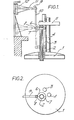
- apparatus of the invention Adjacent to the electrodes is positioned apparatus of the invention comprising arcuate spray units 6 and 7 mounted on a support 8 which is pivotally mounted on support arm 9 by means of connecting tube 10.
- the support arm 9 is movable laterally within guide tube 11 and the guide tube is fixed to pivot axle 12 which is mounted to permit pivoting movement of the guide tube 11 and the support arm 9 in a horizontal plane.
- the mounting of the pivot axle 12 is such that the axle with the guide tube 11 and support arm 9 can be moved up and down in a vertical plane e.g. from the position shown in full lines in Figure 1 to that shown in dotted lines.
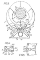
- the support 8 and the mounting on this of the arcuate spray units are shown in greater detail in Figure 3.
- the support 8 carries pneumatic or hydraulic cylinders 13 and 14 having respective piston rods 15 and 16.
- the piston rods 15 and 16 are attached to the spray units 7 and 6 respectively by respective pivot joints 18 and 17.
- Arms 19 and 20 are attached at one end to the support 8 by respective pivot joints 21 and 22 and at the other end to the spray units 6 and 7 by respective pivot joints 23 and 24.
- the piston rods 13 and 14 By use of the cylinders 13 and 14 the piston rods can be driven out to reach positions 25 and 26 respectively as a result of which the arcuate spray units 6 and 7 take up the positions shown in dotted lines in Figure 3 and the arms 19 and 20 pivot to the positions shown in dotted lines in the Figure.
- each of the spray units has six nozzles 27 of fish-tail shape, each being the outlet for particulate matter entained in gas from a respective chamber 28.
- Each of the chambers 28 has an inlet nozzle 29 for gas under pressure and, mounted above each of the chambers and communicating with the chamber by a duct is a hopper 30 for a supply of particulate matter.
- a single duct 31 is present for the supply of gas under pressure to all the chambers of each of the spray units a single duct 31 is present.
- the hoppers 30 are provided with a lid 32.
- the hoppers 30 are charged with particulate matter for providing a coating on a hot graphite electrode to protect it from oxidation.
- the spray units are positioned as shown in Figure 1 by moving the connecting tube 10 to the position shown and by closing the previously open spray units 6 and 7 around the hot electrode 2 as described in connection with Figure 3.
- the gas under pressure is then supplied to the duct 31 of each of the spray units.
- the pressurised gas enters each of the chambers through the nozzle 29 and entrains particulate matter entering the chamber from the hopper and the gas-entrained matter leaves the chambers through the nozzles 27.
- the particulate matter adheres to the hot electrode to form a coating to protect the graphite from oxidation.
- the mounting of the guide tube 11 is gradually moved downwards until the assembly reaches the position shown in dotted lines in Figure 1 and thus substantially all of the side of the electrode between the clamp 5 and the top of the roof 1 is given the coating.
- One or more further traverses may be carried out if desired to increase the amount of matter applied to the electrode.
- the supply of gas under pressure is cut off and the spray units are removed from the electrode.
- the other electrodes may then similarly be provided with a coating or this may be done on subsequent occasions when the roof is swung aside from the furnace and the electrodes are hot. of particles each containing both a graphite-wetting fusible matrix material and a refractory filler.
- Particulate matter according to claim 3 characterised in that it comprises at least 90% by weight of particles each containing both a graphite-wetting fusible matrix material and a refractory filler.
- refractory filler comprises at least one refractory metal, oxide, aluminosilicate, carbide, nitride, silicide or boride.
- Particulate matter according to any of claims 2 to 6 characterised in that the particulate matter comprises 30 to 80% by weight of refractory filler and 20 to 70% by weight of graphite-wetting fusible matrix material.
Landscapes
- Chemical & Material Sciences (AREA)
- Engineering & Computer Science (AREA)
- Ceramic Engineering (AREA)
- Materials Engineering (AREA)
- Structural Engineering (AREA)
- Organic Chemistry (AREA)
- Inorganic Chemistry (AREA)
- Plasma & Fusion (AREA)
- Physics & Mathematics (AREA)
- Vertical, Hearth, Or Arc Furnaces (AREA)
- Furnace Details (AREA)
- Discharge Heating (AREA)
- Refinement Of Pig-Iron, Manufacture Of Cast Iron, And Steel Manufacture Other Than In Revolving Furnaces (AREA)
Priority Applications (1)
| Application Number | Priority Date | Filing Date | Title |
|---|---|---|---|
| AT82303052T ATE27445T1 (de) | 1981-06-26 | 1982-06-14 | Protektion von graphit elektroden. |
Applications Claiming Priority (4)
| Application Number | Priority Date | Filing Date | Title |
|---|---|---|---|
| GB8119714 | 1981-06-26 | ||
| GB8119714 | 1981-06-26 | ||
| GB8208226 | 1982-03-20 | ||
| GB8208226 | 1982-03-20 |
Related Child Applications (2)
| Application Number | Title | Priority Date | Filing Date |
|---|---|---|---|
| EP86105513A Division EP0200983A3 (de) | 1981-06-26 | 1982-06-14 | Protektion von Graphitelektroden |
| EP86105513A Division-Into EP0200983A3 (de) | 1981-06-26 | 1982-06-14 | Protektion von Graphitelektroden |
Publications (3)
| Publication Number | Publication Date |
|---|---|
| EP0070100A2 true EP0070100A2 (de) | 1983-01-19 |
| EP0070100A3 EP0070100A3 (en) | 1985-02-06 |
| EP0070100B1 EP0070100B1 (de) | 1987-05-27 |
Family
ID=26279922
Family Applications (2)
| Application Number | Title | Priority Date | Filing Date |
|---|---|---|---|
| EP19820303052 Expired EP0070100B1 (de) | 1981-06-26 | 1982-06-14 | Protektion von Graphit elektroden |
| EP86105513A Withdrawn EP0200983A3 (de) | 1981-06-26 | 1982-06-14 | Protektion von Graphitelektroden |
Family Applications After (1)
| Application Number | Title | Priority Date | Filing Date |
|---|---|---|---|
| EP86105513A Withdrawn EP0200983A3 (de) | 1981-06-26 | 1982-06-14 | Protektion von Graphitelektroden |
Country Status (3)
| Country | Link |
|---|---|
| EP (2) | EP0070100B1 (de) |
| DE (1) | DE3276427D1 (de) |
| ES (2) | ES513471A0 (de) |
Cited By (5)
| Publication number | Priority date | Publication date | Assignee | Title |
|---|---|---|---|---|
| FR2620356A1 (fr) * | 1987-09-14 | 1989-03-17 | Lesieur Bernard | Appareillage pour l'application de traitements de surfaces a des structures allongees |
| EP0252621A3 (de) * | 1986-07-05 | 1989-06-07 | Foseco International Limited | Schutz von Graphitelektroden |
| WO2004065331A1 (en) * | 2003-01-21 | 2004-08-05 | Equity Enterprises | Surface hardened carbon material and process of manufacturing |
| EP2190262A1 (de) | 2008-11-25 | 2010-05-26 | SGL Carbon SE | Kohlenstoffelektrode mit verlängerter Standzeit |
| CN102338661A (zh) * | 2011-05-23 | 2012-02-01 | 桂林理工大学 | 夹式水平电极架 |
Families Citing this family (1)
| Publication number | Priority date | Publication date | Assignee | Title |
|---|---|---|---|---|
| EP0490000A1 (de) * | 1990-12-14 | 1992-06-17 | The Kendall Company | Vorrichtung zum Auftragen eines flüssigen Beschichtungsmittels für einen zylindrischen Gegenstand |
Family Cites Families (7)
| Publication number | Priority date | Publication date | Assignee | Title |
|---|---|---|---|---|
| FR1369372A (fr) * | 1963-04-24 | 1964-08-14 | Thomson Houston Comp Francaise | Revêtement métallisant pour corps macrocristallin en oxydes métalliques réfractaires |
| US3620799A (en) * | 1968-12-26 | 1971-11-16 | Rca Corp | Method for metallizing a ceramic body |
| GB1386611A (en) * | 1971-11-26 | 1975-03-12 | Foseco Int | Protection of graphite electrodes |
| GB1431892A (en) * | 1972-03-22 | 1976-04-14 | Foseco Int | Pre-formed sheets for use in the protection of carbon articles |
| FR2191450A5 (de) * | 1972-06-30 | 1974-02-01 | Brochet Ernest | |
| US4076175A (en) * | 1976-08-24 | 1978-02-28 | Bert Walter J | Adjustable industrial paint sprayer |
| DE2731894C3 (de) * | 1977-07-14 | 1980-07-17 | Roland 8702 Veitshoechheim Kraus | Farbauftragverfahren und Vorrichtung zur Durchführung des Verfahrens |
-
1982
- 1982-06-14 EP EP19820303052 patent/EP0070100B1/de not_active Expired
- 1982-06-14 EP EP86105513A patent/EP0200983A3/de not_active Withdrawn
- 1982-06-14 DE DE8282303052T patent/DE3276427D1/de not_active Expired
- 1982-06-25 ES ES513471A patent/ES513471A0/es active Granted
-
1983
- 1983-05-12 ES ES522327A patent/ES8407108A1/es not_active Expired
Cited By (6)
| Publication number | Priority date | Publication date | Assignee | Title |
|---|---|---|---|---|
| EP0252621A3 (de) * | 1986-07-05 | 1989-06-07 | Foseco International Limited | Schutz von Graphitelektroden |
| FR2620356A1 (fr) * | 1987-09-14 | 1989-03-17 | Lesieur Bernard | Appareillage pour l'application de traitements de surfaces a des structures allongees |
| EP0307527A1 (de) * | 1987-09-14 | 1989-03-22 | Bernard Lesieur | Apparat zur Oberflächenbehandlung von langen Strukturen |
| WO2004065331A1 (en) * | 2003-01-21 | 2004-08-05 | Equity Enterprises | Surface hardened carbon material and process of manufacturing |
| EP2190262A1 (de) | 2008-11-25 | 2010-05-26 | SGL Carbon SE | Kohlenstoffelektrode mit verlängerter Standzeit |
| CN102338661A (zh) * | 2011-05-23 | 2012-02-01 | 桂林理工大学 | 夹式水平电极架 |
Also Published As
| Publication number | Publication date |
|---|---|
| EP0200983A3 (de) | 1989-01-04 |
| ES522327A0 (es) | 1984-08-16 |
| ES8407108A1 (es) | 1984-08-16 |
| EP0070100B1 (de) | 1987-05-27 |
| ES8400498A1 (es) | 1983-11-01 |
| ES513471A0 (es) | 1983-11-01 |
| EP0200983A2 (de) | 1986-11-12 |
| EP0070100A3 (en) | 1985-02-06 |
| DE3276427D1 (en) | 1987-07-02 |
Similar Documents
| Publication | Publication Date | Title |
|---|---|---|
| US20030091755A1 (en) | Coating method | |
| US2968083A (en) | Hot patching of refractory structures | |
| EP0070100A2 (de) | Protektion von Graphit elektroden | |
| JPH11501367A (ja) | 鋼板の亜鉛被覆装置および亜鉛被覆方法 | |
| EP0143429A1 (de) | Verfahren und Vorrichtung zum Speisen eines Schmelzvorganges durch oberflächliches Abschmelzen | |
| US4048348A (en) | Method of applying a fused silica coating to a substrate | |
| CA1175221A (en) | Protection of graphite electrodes | |
| US4946806A (en) | Flame spraying method and composition | |
| JPH06182501A (ja) | 金属の連続鋳造方法及び装置 | |
| JPS6312359B2 (de) | ||
| GB2117417A (en) | Producing high-purity ceramics- free metallic powders | |
| US4772514A (en) | Protective layer for carbonaceous materials and method of applying the same | |
| JP4331879B2 (ja) | 高炉の炉下部内壁面構造 | |
| US4570568A (en) | Shroud for thermally sprayed workpiece | |
| CA1119768A (en) | Continuous casting shroud apparatus and method | |
| CN1116974A (zh) | -325目颗粒均一的锌粉制备方法 | |
| CA1288202C (en) | Protection of graphite electrodes | |
| GB2169279A (en) | Producing mineral fibres | |
| US4707379A (en) | Protective layer for carbonaceous materials and method of applying the same | |
| NL9402019A (nl) | Werkwijze en poedermengsel voor het repareren van op oxide gebaseerde vuurvaste lichamen. | |
| CA2071675C (en) | Ceramic welding | |
| CA2019049A1 (en) | Method and apparatus for equalization of temperature in a forehearth in glass manufacture | |
| RU2165985C1 (ru) | Устройство для загрузки восстанавливаемой железорудной мелочи непосредственно в плавильный газификатор | |
| CA1177228A (en) | Method of anti-corrosive protection of silicon carbide products | |
| JPH09104869A (ja) | コークス炉内煉瓦表面へのカーボン附着抑制方法 |
Legal Events
| Date | Code | Title | Description |
|---|---|---|---|
| PUAI | Public reference made under article 153(3) epc to a published international application that has entered the european phase |
Free format text: ORIGINAL CODE: 0009012 |
|
| AK | Designated contracting states |
Designated state(s): AT BE CH DE FR GB IT LI LU NL SE |
|
| 17P | Request for examination filed |
Effective date: 19830218 |
|
| PUAL | Search report despatched |
Free format text: ORIGINAL CODE: 0009013 |
|
| AK | Designated contracting states |
Designated state(s): AT BE CH DE FR GB IT LI LU NL SE |
|
| RAP1 | Party data changed (applicant data changed or rights of an application transferred) |
Owner name: FOSECO INTERNATIONAL LIMITED |
|
| GRAA | (expected) grant |
Free format text: ORIGINAL CODE: 0009210 |
|
| AK | Designated contracting states |
Kind code of ref document: B1 Designated state(s): AT BE CH DE FR GB IT LI LU NL SE |
|
| REF | Corresponds to: |
Ref document number: 27445 Country of ref document: AT Date of ref document: 19870615 Kind code of ref document: T |
|
| ITF | It: translation for a ep patent filed | ||
| PG25 | Lapsed in a contracting state [announced via postgrant information from national office to epo] |
Ref country code: LU Free format text: LAPSE BECAUSE OF NON-PAYMENT OF DUE FEES Effective date: 19870630 |
|
| REF | Corresponds to: |
Ref document number: 3276427 Country of ref document: DE Date of ref document: 19870702 |
|
| ET | Fr: translation filed | ||
| PLBE | No opposition filed within time limit |
Free format text: ORIGINAL CODE: 0009261 |
|
| STAA | Information on the status of an ep patent application or granted ep patent |
Free format text: STATUS: NO OPPOSITION FILED WITHIN TIME LIMIT |
|
| 26N | No opposition filed | ||
| PGFP | Annual fee paid to national office [announced via postgrant information from national office to epo] |
Ref country code: FR Payment date: 19900510 Year of fee payment: 9 Ref country code: AT Payment date: 19900510 Year of fee payment: 9 |
|
| PGFP | Annual fee paid to national office [announced via postgrant information from national office to epo] |
Ref country code: GB Payment date: 19900515 Year of fee payment: 9 |
|
| PGFP | Annual fee paid to national office [announced via postgrant information from national office to epo] |
Ref country code: SE Payment date: 19900516 Year of fee payment: 9 |
|
| PGFP | Annual fee paid to national office [announced via postgrant information from national office to epo] |
Ref country code: BE Payment date: 19900518 Year of fee payment: 9 |
|
| PGFP | Annual fee paid to national office [announced via postgrant information from national office to epo] |
Ref country code: LU Payment date: 19900523 Year of fee payment: 9 |
|
| PGFP | Annual fee paid to national office [announced via postgrant information from national office to epo] |
Ref country code: DE Payment date: 19900530 Year of fee payment: 9 |
|
| ITTA | It: last paid annual fee | ||
| PG25 | Lapsed in a contracting state [announced via postgrant information from national office to epo] |
Ref country code: GB Effective date: 19910614 Ref country code: AT Effective date: 19910614 |
|
| PG25 | Lapsed in a contracting state [announced via postgrant information from national office to epo] |
Ref country code: SE Effective date: 19910615 |
|
| PG25 | Lapsed in a contracting state [announced via postgrant information from national office to epo] |
Ref country code: BE Effective date: 19910630 |
|
| PGFP | Annual fee paid to national office [announced via postgrant information from national office to epo] |
Ref country code: NL Payment date: 19910630 Year of fee payment: 10 |
|
| BERE | Be: lapsed |
Owner name: FOSECO INTERNATIONAL LTD Effective date: 19910630 |
|
| GBPC | Gb: european patent ceased through non-payment of renewal fee | ||
| PG25 | Lapsed in a contracting state [announced via postgrant information from national office to epo] |
Ref country code: FR Effective date: 19920228 |
|
| PG25 | Lapsed in a contracting state [announced via postgrant information from national office to epo] |
Ref country code: DE Effective date: 19920401 |
|
| REG | Reference to a national code |
Ref country code: FR Ref legal event code: ST |
|
| PGFP | Annual fee paid to national office [announced via postgrant information from national office to epo] |
Ref country code: CH Payment date: 19920521 Year of fee payment: 11 |
|
| PG25 | Lapsed in a contracting state [announced via postgrant information from national office to epo] |
Ref country code: NL Effective date: 19930101 |
|
| NLV4 | Nl: lapsed or anulled due to non-payment of the annual fee | ||
| PG25 | Lapsed in a contracting state [announced via postgrant information from national office to epo] |
Ref country code: LI Effective date: 19930630 Ref country code: CH Effective date: 19930630 |
|
| REG | Reference to a national code |
Ref country code: CH Ref legal event code: PL |
|
| EUG | Se: european patent has lapsed |
Ref document number: 82303052.3 Effective date: 19920109 |