EP0069996A1 - Heat pump air conditioning system - Google Patents
Heat pump air conditioning system Download PDFInfo
- Publication number
- EP0069996A1 EP0069996A1 EP82106126A EP82106126A EP0069996A1 EP 0069996 A1 EP0069996 A1 EP 0069996A1 EP 82106126 A EP82106126 A EP 82106126A EP 82106126 A EP82106126 A EP 82106126A EP 0069996 A1 EP0069996 A1 EP 0069996A1
- Authority
- EP
- European Patent Office
- Prior art keywords
- refrigerant
- heat exchanger
- temperature
- compressor
- storage tank
- Prior art date
- Legal status (The legal status is an assumption and is not a legal conclusion. Google has not performed a legal analysis and makes no representation as to the accuracy of the status listed.)
- Granted
Links
- 238000004378 air conditioning Methods 0.000 title claims abstract description 78
- XLYOFNOQVPJJNP-UHFFFAOYSA-N water Substances O XLYOFNOQVPJJNP-UHFFFAOYSA-N 0.000 claims abstract description 82
- 238000005057 refrigeration Methods 0.000 claims abstract description 68
- 239000003507 refrigerant Substances 0.000 claims description 165
- 230000001276 controlling effect Effects 0.000 claims description 32
- 238000012546 transfer Methods 0.000 claims description 23
- 230000006698 induction Effects 0.000 claims description 11
- 238000010521 absorption reaction Methods 0.000 claims description 8
- 239000003570 air Substances 0.000 claims description 8
- 239000012080 ambient air Substances 0.000 claims description 8
- 230000004044 response Effects 0.000 claims description 8
- 230000033228 biological regulation Effects 0.000 claims description 3
- 230000001105 regulatory effect Effects 0.000 claims description 3
- 238000005070 sampling Methods 0.000 claims description 2
- 238000012937 correction Methods 0.000 claims 4
- 238000004804 winding Methods 0.000 claims 2
- 229920000136 polysorbate Polymers 0.000 claims 1
- 238000011084 recovery Methods 0.000 claims 1
- 238000010438 heat treatment Methods 0.000 abstract description 35
- 238000001816 cooling Methods 0.000 abstract description 26
- 230000000422 nocturnal effect Effects 0.000 abstract description 3
- 229920006395 saturated elastomer Polymers 0.000 description 33
- 238000010586 diagram Methods 0.000 description 30
- 238000001704 evaporation Methods 0.000 description 21
- 230000007423 decrease Effects 0.000 description 12
- 230000005855 radiation Effects 0.000 description 10
- 239000007788 liquid Substances 0.000 description 5
- 238000004364 calculation method Methods 0.000 description 4
- 238000013461 design Methods 0.000 description 4
- 230000006872 improvement Effects 0.000 description 3
- 238000000034 method Methods 0.000 description 3
- 238000007906 compression Methods 0.000 description 2
- 238000002474 experimental method Methods 0.000 description 2
- 239000012530 fluid Substances 0.000 description 2
- 238000007710 freezing Methods 0.000 description 2
- 230000008014 freezing Effects 0.000 description 2
- 238000012986 modification Methods 0.000 description 2
- 230000004048 modification Effects 0.000 description 2
- 230000008569 process Effects 0.000 description 2
- 230000035945 sensitivity Effects 0.000 description 2
- 238000004088 simulation Methods 0.000 description 2
- 238000011144 upstream manufacturing Methods 0.000 description 2
- 230000001133 acceleration Effects 0.000 description 1
- 238000009825 accumulation Methods 0.000 description 1
- 230000009471 action Effects 0.000 description 1
- 230000003044 adaptive effect Effects 0.000 description 1
- 238000013459 approach Methods 0.000 description 1
- 230000008901 benefit Effects 0.000 description 1
- 230000015556 catabolic process Effects 0.000 description 1
- 230000008859 change Effects 0.000 description 1
- 230000006835 compression Effects 0.000 description 1
- 238000010276 construction Methods 0.000 description 1
- 239000013078 crystal Substances 0.000 description 1
- 125000004122 cyclic group Chemical group 0.000 description 1
- 230000001351 cycling effect Effects 0.000 description 1
- 238000006731 degradation reaction Methods 0.000 description 1
- 230000001419 dependent effect Effects 0.000 description 1
- 238000009795 derivation Methods 0.000 description 1
- 230000000694 effects Effects 0.000 description 1
- 230000007613 environmental effect Effects 0.000 description 1
- 238000013213 extrapolation Methods 0.000 description 1
- 230000005484 gravity Effects 0.000 description 1
- 230000017525 heat dissipation Effects 0.000 description 1
- 239000007791 liquid phase Substances 0.000 description 1
- 238000005259 measurement Methods 0.000 description 1
- 239000000203 mixture Substances 0.000 description 1
- 238000013021 overheating Methods 0.000 description 1
- 238000012354 overpressurization Methods 0.000 description 1
- 239000012071 phase Substances 0.000 description 1
- 238000005381 potential energy Methods 0.000 description 1
- 238000012545 processing Methods 0.000 description 1
- 230000031070 response to heat Effects 0.000 description 1
- 239000011555 saturated liquid Substances 0.000 description 1
- 239000007787 solid Substances 0.000 description 1
- 238000010257 thawing Methods 0.000 description 1
- 239000012808 vapor phase Substances 0.000 description 1
- 239000002699 waste material Substances 0.000 description 1
Images


Classifications
-
- F—MECHANICAL ENGINEERING; LIGHTING; HEATING; WEAPONS; BLASTING
- F24—HEATING; RANGES; VENTILATING
- F24F—AIR-CONDITIONING; AIR-HUMIDIFICATION; VENTILATION; USE OF AIR CURRENTS FOR SCREENING
- F24F5/00—Air-conditioning systems or apparatus not covered by F24F1/00 or F24F3/00, e.g. using solar heat or combined with household units such as an oven or water heater
- F24F5/0046—Air-conditioning systems or apparatus not covered by F24F1/00 or F24F3/00, e.g. using solar heat or combined with household units such as an oven or water heater using natural energy, e.g. solar energy, energy from the ground
-
- F—MECHANICAL ENGINEERING; LIGHTING; HEATING; WEAPONS; BLASTING
- F24—HEATING; RANGES; VENTILATING
- F24D—DOMESTIC- OR SPACE-HEATING SYSTEMS, e.g. CENTRAL HEATING SYSTEMS; DOMESTIC HOT-WATER SUPPLY SYSTEMS; ELEMENTS OR COMPONENTS THEREFOR
- F24D11/00—Central heating systems using heat accumulated in storage masses
- F24D11/02—Central heating systems using heat accumulated in storage masses using heat pumps
- F24D11/0257—Central heating systems using heat accumulated in storage masses using heat pumps air heating system
- F24D11/0264—Central heating systems using heat accumulated in storage masses using heat pumps air heating system combined with solar energy
-
- F—MECHANICAL ENGINEERING; LIGHTING; HEATING; WEAPONS; BLASTING
- F25—REFRIGERATION OR COOLING; COMBINED HEATING AND REFRIGERATION SYSTEMS; HEAT PUMP SYSTEMS; MANUFACTURE OR STORAGE OF ICE; LIQUEFACTION SOLIDIFICATION OF GASES
- F25B—REFRIGERATION MACHINES, PLANTS OR SYSTEMS; COMBINED HEATING AND REFRIGERATION SYSTEMS; HEAT PUMP SYSTEMS
- F25B49/00—Arrangement or mounting of control or safety devices
- F25B49/02—Arrangement or mounting of control or safety devices for compression type machines, plants or systems
-
- G—PHYSICS
- G05—CONTROLLING; REGULATING
- G05D—SYSTEMS FOR CONTROLLING OR REGULATING NON-ELECTRIC VARIABLES
- G05D23/00—Control of temperature
- G05D23/19—Control of temperature characterised by the use of electric means
- G05D23/1917—Control of temperature characterised by the use of electric means using digital means
-
- F—MECHANICAL ENGINEERING; LIGHTING; HEATING; WEAPONS; BLASTING
- F25—REFRIGERATION OR COOLING; COMBINED HEATING AND REFRIGERATION SYSTEMS; HEAT PUMP SYSTEMS; MANUFACTURE OR STORAGE OF ICE; LIQUEFACTION SOLIDIFICATION OF GASES
- F25B—REFRIGERATION MACHINES, PLANTS OR SYSTEMS; COMBINED HEATING AND REFRIGERATION SYSTEMS; HEAT PUMP SYSTEMS
- F25B13/00—Compression machines, plants or systems, with reversible cycle
-
- F—MECHANICAL ENGINEERING; LIGHTING; HEATING; WEAPONS; BLASTING
- F25—REFRIGERATION OR COOLING; COMBINED HEATING AND REFRIGERATION SYSTEMS; HEAT PUMP SYSTEMS; MANUFACTURE OR STORAGE OF ICE; LIQUEFACTION SOLIDIFICATION OF GASES
- F25B—REFRIGERATION MACHINES, PLANTS OR SYSTEMS; COMBINED HEATING AND REFRIGERATION SYSTEMS; HEAT PUMP SYSTEMS
- F25B25/00—Machines, plants or systems, using a combination of modes of operation covered by two or more of the groups F25B1/00 - F25B23/00
- F25B25/005—Machines, plants or systems, using a combination of modes of operation covered by two or more of the groups F25B1/00 - F25B23/00 using primary and secondary systems
-
- F—MECHANICAL ENGINEERING; LIGHTING; HEATING; WEAPONS; BLASTING
- F25—REFRIGERATION OR COOLING; COMBINED HEATING AND REFRIGERATION SYSTEMS; HEAT PUMP SYSTEMS; MANUFACTURE OR STORAGE OF ICE; LIQUEFACTION SOLIDIFICATION OF GASES
- F25B—REFRIGERATION MACHINES, PLANTS OR SYSTEMS; COMBINED HEATING AND REFRIGERATION SYSTEMS; HEAT PUMP SYSTEMS
- F25B2600/00—Control issues
- F25B2600/02—Compressor control
- F25B2600/025—Compressor control by controlling speed
- F25B2600/0253—Compressor control by controlling speed with variable speed
-
- F—MECHANICAL ENGINEERING; LIGHTING; HEATING; WEAPONS; BLASTING
- F25—REFRIGERATION OR COOLING; COMBINED HEATING AND REFRIGERATION SYSTEMS; HEAT PUMP SYSTEMS; MANUFACTURE OR STORAGE OF ICE; LIQUEFACTION SOLIDIFICATION OF GASES
- F25B—REFRIGERATION MACHINES, PLANTS OR SYSTEMS; COMBINED HEATING AND REFRIGERATION SYSTEMS; HEAT PUMP SYSTEMS
- F25B2600/00—Control issues
- F25B2600/21—Refrigerant outlet evaporator temperature
-
- F—MECHANICAL ENGINEERING; LIGHTING; HEATING; WEAPONS; BLASTING
- F25—REFRIGERATION OR COOLING; COMBINED HEATING AND REFRIGERATION SYSTEMS; HEAT PUMP SYSTEMS; MANUFACTURE OR STORAGE OF ICE; LIQUEFACTION SOLIDIFICATION OF GASES
- F25B—REFRIGERATION MACHINES, PLANTS OR SYSTEMS; COMBINED HEATING AND REFRIGERATION SYSTEMS; HEAT PUMP SYSTEMS
- F25B2700/00—Sensing or detecting of parameters; Sensors therefor
- F25B2700/21—Temperatures
- F25B2700/2106—Temperatures of fresh outdoor air
-
- Y—GENERAL TAGGING OF NEW TECHNOLOGICAL DEVELOPMENTS; GENERAL TAGGING OF CROSS-SECTIONAL TECHNOLOGIES SPANNING OVER SEVERAL SECTIONS OF THE IPC; TECHNICAL SUBJECTS COVERED BY FORMER USPC CROSS-REFERENCE ART COLLECTIONS [XRACs] AND DIGESTS
- Y02—TECHNOLOGIES OR APPLICATIONS FOR MITIGATION OR ADAPTATION AGAINST CLIMATE CHANGE
- Y02B—CLIMATE CHANGE MITIGATION TECHNOLOGIES RELATED TO BUILDINGS, e.g. HOUSING, HOUSE APPLIANCES OR RELATED END-USER APPLICATIONS
- Y02B10/00—Integration of renewable energy sources in buildings
- Y02B10/20—Solar thermal
-
- Y—GENERAL TAGGING OF NEW TECHNOLOGICAL DEVELOPMENTS; GENERAL TAGGING OF CROSS-SECTIONAL TECHNOLOGIES SPANNING OVER SEVERAL SECTIONS OF THE IPC; TECHNICAL SUBJECTS COVERED BY FORMER USPC CROSS-REFERENCE ART COLLECTIONS [XRACs] AND DIGESTS
- Y02—TECHNOLOGIES OR APPLICATIONS FOR MITIGATION OR ADAPTATION AGAINST CLIMATE CHANGE
- Y02B—CLIMATE CHANGE MITIGATION TECHNOLOGIES RELATED TO BUILDINGS, e.g. HOUSING, HOUSE APPLIANCES OR RELATED END-USER APPLICATIONS
- Y02B10/00—Integration of renewable energy sources in buildings
- Y02B10/70—Hybrid systems, e.g. uninterruptible or back-up power supplies integrating renewable energies
-
- Y—GENERAL TAGGING OF NEW TECHNOLOGICAL DEVELOPMENTS; GENERAL TAGGING OF CROSS-SECTIONAL TECHNOLOGIES SPANNING OVER SEVERAL SECTIONS OF THE IPC; TECHNICAL SUBJECTS COVERED BY FORMER USPC CROSS-REFERENCE ART COLLECTIONS [XRACs] AND DIGESTS
- Y02—TECHNOLOGIES OR APPLICATIONS FOR MITIGATION OR ADAPTATION AGAINST CLIMATE CHANGE
- Y02B—CLIMATE CHANGE MITIGATION TECHNOLOGIES RELATED TO BUILDINGS, e.g. HOUSING, HOUSE APPLIANCES OR RELATED END-USER APPLICATIONS
- Y02B30/00—Energy efficient heating, ventilation or air conditioning [HVAC]
- Y02B30/12—Hot water central heating systems using heat pumps
-
- Y—GENERAL TAGGING OF NEW TECHNOLOGICAL DEVELOPMENTS; GENERAL TAGGING OF CROSS-SECTIONAL TECHNOLOGIES SPANNING OVER SEVERAL SECTIONS OF THE IPC; TECHNICAL SUBJECTS COVERED BY FORMER USPC CROSS-REFERENCE ART COLLECTIONS [XRACs] AND DIGESTS
- Y02—TECHNOLOGIES OR APPLICATIONS FOR MITIGATION OR ADAPTATION AGAINST CLIMATE CHANGE
- Y02B—CLIMATE CHANGE MITIGATION TECHNOLOGIES RELATED TO BUILDINGS, e.g. HOUSING, HOUSE APPLIANCES OR RELATED END-USER APPLICATIONS
- Y02B30/00—Energy efficient heating, ventilation or air conditioning [HVAC]
- Y02B30/13—Hot air central heating systems using heat pumps
-
- Y—GENERAL TAGGING OF NEW TECHNOLOGICAL DEVELOPMENTS; GENERAL TAGGING OF CROSS-SECTIONAL TECHNOLOGIES SPANNING OVER SEVERAL SECTIONS OF THE IPC; TECHNICAL SUBJECTS COVERED BY FORMER USPC CROSS-REFERENCE ART COLLECTIONS [XRACs] AND DIGESTS
- Y02—TECHNOLOGIES OR APPLICATIONS FOR MITIGATION OR ADAPTATION AGAINST CLIMATE CHANGE
- Y02B—CLIMATE CHANGE MITIGATION TECHNOLOGIES RELATED TO BUILDINGS, e.g. HOUSING, HOUSE APPLIANCES OR RELATED END-USER APPLICATIONS
- Y02B30/00—Energy efficient heating, ventilation or air conditioning [HVAC]
- Y02B30/70—Efficient control or regulation technologies, e.g. for control of refrigerant flow, motor or heating
Definitions
- the present invention relates to a heat pump air conditioning system performing a refrigeration cycle having a compressor for compressing refrigerant, means for exchanging heat including an evapolator for evapolating the refrigerant and a condenser for condensing the refrigerant, and expansion valve for controlling the passage of the refrigerant and more particularly to an improvement of coefficients of performance by an active control of a refrigeration cycle in the system.
- the coefficients of performance generally tends to be lowered when the outdoor temperature becomes either too low or too high compared to a nominal design temperature, even if the coefficient of performance is maximized or optimized for the nominal indoor and outdoor temperatures and the indoor heat load at the nominal design temperature, since an opening of an expansion valve and a rotation speed of a rotary compressor are almost fixed at this design condition in the prior art heat pump air conditioning system.
- a room temperature of a house is regulated collectively, not individually, based upon the average temperature thereof.
- This system has such disadvantages that unused rooms are warmed up unnecessarily, resulting in energy waste, while rooms remote from the heat source tend to have a lower temperature due to the temperature drop in the pipings, etc.
- a heat pump air conditioning system comprises a refrigeration cycle having a compressor for compressing refrigerant, means for exchanging heat including an evapolator for evapolating the refrigerant and a condenser for condensing the refrigerant, and expansion valve for controlling the passage of the refrigerant; first means for measuring-an ambient temperature; second means for measuring a temperature of the refrigerant; third means for measuring a pressure of the refrigerant; and controlling means receiving the measured data of the ambient temperature, the temperature of the refrigerant and the pressure of the refrigerant for controlling a rotational speed of the compressor and an opening of the expansion valve in accordance with the measured data to maximize an coefficient of performance of the refrigeration cycle.
- an open and close loop control of the refrigeration cycle is performed to follow a desired refrigeration cycle in the following manner.
- Temperature sensors are arranged in the refrigeration cycle to monitor the state variables thereof. Based on these measured state variables, real-time control of the rotational speed of the rotary compressor and the opening of the expansion valve are made continuously by processing data from the sensors by a control unit such as a microprocessor.
- a solar collector as a second outdoor heat exchanger in parallel with an outdoor heat exchanger such one as for an existing heat pump air conditioning system, so that this second outdoor heat exchanger is selectively used when either the solar heating or night sky cooling means is effective to collect or dissipate a correct amount of heat energy under a command from the control means to store the thus heated or cooled water temporarily in a storage tank.
- a heat pump air conditioning system comprises a refrigeration cycle having: an outdoor heat exchanger installed outdoors for exchanging heat via refrigerant; a solar collector coupled in parallel with the outdoor heat exchanger for collecting solar-energy; means for selecting one of the outdoor heat exchanger and the solar collector at a time for heat transfer between the refrigerant and outdoor ambient air and/or heat radiating objects; a compressor coupled to the outdoor heat exchanger and the solar collector for compressing the refrigerant; an expansion valve coupled to the outdoor heat exchanger and the solar collector for controlling a flow rate of the refrigerant; and at least one of an indoor heat exchanger installed indoors and a storage tank heat exchanger disposed in a storage tank, each of which acts as a condenser when the outdoor heat exchanger or the solar collector is used as an evaporator and acts as an evaporator when the outdoor heat exchanger or the solar collector is used as a condenser, for transferring heat between the refrigerant and indoor and outdoor air and between the
- a heat pump air conditioning system comprises an outdoor heat exchanger installed outdoors for exchanging heat via refrigerant; a solar collector coupled in parallel with the outdoor heat exchanger for collecting solar energy; means for selecting one of the outdoor heat exchanger and the solar collector at a time for heat transfer between the refrigerant and outdoor ambient air and/or heat radiating objects; a compressor coupled to the outdoor heat exchanger and the solar collector for compressing the refrigerant; an expansion valve coupled to the outdoor heat exchanger and the solar collector for controlling a flow rate of the refrigerant; a storage tank heat exchanger disposed in a storage tank which acts as a condenser when the outdoor heat exchanger or the solar collector is used as an evaporator and acts as an evaporator when the outdoor heat exchanger or the solar collector is used as a condenser, for transferring heat between the refrigerant and the water in the storage tank, the storage tank storing the water performed the heat exchange with the refrigerant in the storage tank heat exchanger; and means for
- a heat pump air conditioning system comprises an outdoor heat exchanger installed outdoors for exchanging heat via refrigerant; a solar collector coupled in parallel with the outdoor heat exchanger for collecting solar energy; means for selecting one of the outdoor heat exchanger and the solar collector at a time for heat transfer between the refrigerant and outdoor ambient air and/or heat radiating objects; a compressor coupled to the outdoor-heat exchanger and the solar collector for compressing the refrigerant; an expansion valve coupled to the outdoor heat exchanger and the solar collector for controlling a flow rate of the refrigerant; a storage tank heat exchanger disposed in a storage tank which acts as a condenser when the outdoor heat exchanger or the solar collector is used as an evaporator and- acts as an evaporator when the outdoor heat exchanger or the solar collector is used as a condenser, for transferring heat between the refrigerant and the water in the storage tank, the storage tank storing the water performed the heat exchange with the refrigerant
- a circulation pump with a variable rotational speed is disposed in a bus piping, between the storage tank and individual room heat exchangers in various rooms.
- Flow control valves are disposed at the inlets to the individual room heat exchangers.
- the room temperature can be controlled individually by supplying a correct amount of hot or cold water from the storage tank in respsonse to a heat demand from an individual room.
- a coefficient of performance of the heat pump air conditioning system tends to be lowered when an ambient temperature is either too low or too high compared to a nominal ambient temperature. This is because the refrigeration cycle is not optimized with regard to three major variables, i.e., a power input to the heat pump air conditioning system, a heat transfer capability of a refrigerant and a heat transfer rate between the air/water and the refrigerant.
- the power input to the compressor per revolution is proportional to the product of the compressor suction pressure and suction volume.
- the heat distribution capability of the refrigeration cycle to individual rooms will be discussed in the following for cases of a nominal ambient temperature, a lower ambient temperature, and a higher ambient temperature.
- the existing heat pump air conditioning system therefore often needs assistance from an auxiliary heat source such as electric resistance heat when the outdoor temperature is getting cold.
- the temperature gradient between the ambient air and the refrigerant becomes so large that the refrigerant vaporizes fully and are further superheated in the evaporator at this pressure ratio.
- the corresponding T-S diagram is getting slim in shape as shown.in Fig. lc, representing the reduced weight flow rate of the refrigerant due to the specific volume increase of the refrigerant.
- the heat distribution rate of the refrigeration cycle into the individual rooms is shown by the cross hatched area in Fig. lc and is less than that of Fig. lb shown by the dot and dash line in Fig. lc.
- a solar absorption coefficient of the solar collector
- I solar radiation rate per unit area
- k heat conduction coefficient from the solar collector to surrounding atmoshper ti: temperature of the refrigerant (evaporating temperature of the refrigerant)
- t l ambient temperature
- Equation (3) could be converted to as,
- Equating equations (3) and (4), and solving for t 1e gives,
- Equation (4) assumes that the amounts of heat transfer as given by equation (3) is made solely by heat convection from a fictitious ambient atmosphere to the refrigerant.
- t 1e the effective ambient temparature which is typically higher in value than the ambient temperature and corresponds approximately to the temperature of the solar collector in use.
- the night sky radiation is made from the solar collector during clear summer time.
- the effective ambient temperature t le for this case is similarly defined; i.e., the temperature is typically lower than the ambient temperature and corresponds approximately to the temperature of the solar collector in use.
- the detailed derivation of the effective-ambient temperature is not given here for the cooling mode.
- Fig. 2 is the T-S diagram of a reverse Carnot cycle of refrigeration which provides the maximum heat transfer capability.
- Q, and Q 2 are the heat transferred into and out of the cycle, respectively.
- L is the power input to the reverse Carnot cycle per unit refrigerant weight flow which is indicated in Fig. 2 by the area enclosed by cross hatched lines.
- the T-S diagrams of Figs. 3a and 3b compare the actual refrigeration cycle for the existing heat pump air conditioning system to that of the present invention with solar collector. It is noted from the figure that the power input to the compressor is greatly reduced by using solar radiation for a given heat rejection rate Q 2 .
- the power input to the compressor is represented in the T-S diagram by the cross hatched area around which the refrigeration cycle takes place.
- the T-S diagrams of Figs. 3c and 3d are for cooling mode.
- the actual refrigeration cycle of the existing heat pump air conditioning system is compared to that of the present invention with solar collector. By utilizing nocturnal cooling, the condensating temperature of the present invention is lowered for a given heat collection rate Q l , compared to the existing system, thus improving the coefficient of performance.
- the preferred embodiment adaptively varies the pressure ratio of the refrigeration cycle in accordance with its environment to improve the coefficient of performance.
- Figs. 4a and 4b wherein a relationship between the pressure ratio and the volumetric flow rate of the refrigerant is illustrated.
- Fig. 4a there exists a volumetric flow rate of the refrigerant which would maximize the efficiency of the rotary compressor at. a given pressure ratio.
- These points for different pressure ratios can be linked together to form the optimum operating line as shown by a dash and dot line in Fig. 4a.
- the volumetric flow rate of the refrigerant must be controlled as well as the pressure ratio. Therefore, as illustrated in Fig. 4b, both the rotational speed of a rotary compressor 1 and the opening of a variable expansion valve 3 are continuously controlled on real-time basis.
- a refrigeration cycle is so realized that the coefficient of performance at a given operating condition approaches or is substantially equal to its maximum valve.
- the heat pump air conditioning system of the present invention tries to utilize solar heating and night sky cooling as additional heat transfer means, the temperature of the heated or cooled water in the storage tank is not necessarily constant.
- the room temperature is desired to be kept at an approximately constant level, so that the temperature gradient varies between the water in the storage tank and the air in the room.
- This gradient can be compensated for by varying the rotational speed of circulation pump and by metering of individual flow control valve at the inlet of the indoor heat exchanger in each room, thus the fine adjustment of the room temperature can be made individually in response to heat demand of each room, without an on-off control of the compressor.
- the conventional heat pump air conditioning system When the ambient temperature is getting lower, the conventional heat pump air conditioning system has such problems as a degradation of the start-up characteristics of the system and a poor heat conduction characteristic of the outdoor heat exchanger due to the accumulation of frost on the surface of heat exchanger, necessitating an intermittent interruption of the heating mode for defrosting, and causing uncomfort to human in the room.
- These problems are alleviated by the preferred embodiment because a storage tank is installed between the refrigeration cycle and the water distribution network and the open and closed loop control of the refrigeration cycle is performed on a continuous basis.
- “Freon” is used as the refrigerant for this air conditioning system.
- the solar collector 30 and the outdoor heat exchanger 32 are connected in parallel.
- a variable speed rotary compressor 34 compresses low pressure refrigerant vapor into high pressure vapor, and a variable opening expansion valve 36 controls the pressure differential across the valve 36 for a given flow rate of the refrigerant.
- a water storage tank 38 is thermally insulated and stores heated or cooled water at a preprogrammed temperature which will be explained later.
- a storage tank heat exchanger 40 is installed inside the water storage tank 38, and performs heat transfer between the refrigerant and heated or cooled water in the storage tank 38.
- a variable speed circulation pump 42 takes out heated or cooled water in the storage tank 38 from a water exit port 44, to conduct the water into the indoor heat exchanger where heat is rejected or absorbed, and returns it back to a water entrance port 48.
- a reservoir 50 is installed just downstream of the variable opening expansion valve 36 to separate liquid refrigerant from the heat exchanger on a high temperature side from vapor refrigerant not liquefied and to store excess liquid refrigerant which is not in use.
- the reservoir 50 also absorbs, redistributes, and stores excess refrigerant when the operation mode is transferred such as from the solar collector 30 to the outdoor heat exchanger 32 or from the heating to cooling mode, etc.
- the present embodiment has four operational modes; i.e., heating, cooling, solar collector transfer, and outdoor heat exchanger transfer modes of operation.
- Solenoid valves 56, 58, 60 and 62 are activated or deactivated to select the solar collector 30 or the outdoor heat exchanger 32.
- Check valves 64, 66, 68 and 70 are connected in parallel with the solenoid valves 56, 58, 60, and 62, respectively, and bypass the refrigerant to recover it from the heat exchangers not in use at the time of switching the operation mode.
- a four-way valve 72 on the compressor side and a four-way valve 74 on the expansion valve side are to change the flow direction.of the refrigerant in accordance with the heating mode or the cooling mode.
- Each room is equipped with a solenoid valve 78. Whenever the room needs air conditioning, and heated or cooled water is delivered into each room under the command of the solenoid valve 78 of which position is selected manually by a room switch 99.
- a flow control valve 79 regulates the flow rate of heated or cooled water into each room in accordance with the heat demand of that room.
- a solar collector pressure transducer 80, an outdoor heat exchanger pressure transducer 82, and a storage tank heat exchanger pressure transducer 84 measure the saturated vapor pressure of the refrigerant inside the respective heat exchangers.
- a variable speed circulation pump pressure transducer 85 measures an outlet pressure of the variable speed circulation pump 42. These transducers in this embodiment are of strain gauge type and are utilized as safety sensors for overpressurization as well.
- the pressure transducer 80 or 82, and the pressure transducer 84 sense high and low saturated evaporating pressures, respectively, which can be translated into the saturated evaporating temperature and saturated condensing temperature as functions of the respective saturated evaporating pressure.
- a temperature sensor 86 on the inlet side of the variable speed compressor 34 and a temperature sensor 88 on the inlet side of the variable opening expansion valve 36 respectively measure the outlet temperatures of the heat exchangers on a low temperature side and a high temperature side. The temperatures thus measured are then used along with the saturated evaporating temperature mentioned above to calculate the degrees of superheat and subcool which will be described later.
- a solar collector temperature sensor 90 measures the equivalent ambient temperature mentioned earlier, and its output is used with the output of an ambient temperature sensor 92, attached to the outdoor heat exchanger 32, to determine if the solor collector 30 could be used instead of the outdoor heat exchanger 32.
- a storage tank temperature sensor 94 measures the temperature of heated or cooled water in the storage tank 38, and a room temperature sensor 96 measures a temperature inside each room.
- thermister may be used as the temperature sensor.
- a room temperature setting dial 98 can be manipulated to preset the room temperature at a . desired level.
- a room air conditioning switch 99 controls the solenoid valve 78 to conduct the heated or cooled water into only desired rooms.
- a stepping motor 100 continuously varies an opening of the variable opening expansion valve 36, and a variable speed induction motor 102 continuously varies an rotational speed of the variable speed rotary compressor 34.
- a stepping motor 104 and a variable speed induction motor 106 continuously control an opening of the flow control valve 79 and a rotational speed of the variable speed circulation pump 44.
- Reference numeral 110 denotes a control unit.
- the control unit 110 performs such functions as the selection of the operation mode, the switching of each valve, the measurement and control of the rotational speed of the variable speed induction motors 102 and 104 and the opening of the variable opening expansion valve 104.
- control unit 110 and the associated devices are described in detail in the following by referring to the block diagram of Fig. 6. As shown in the diagram the control unit 110 is located inside the dashed lines and is connected to the associated devices shown located outside the dashed lines. The inputs to the control unit 110 are described first.
- the signal obtained from the pressure transducer 80 is voltage amplified and impedance transformed by the signal conditioner provided in the pressure transducer 80 and then is transferred to the control unit 110.
- the signals obtained from other pressure transducers and temperature sensors are similarly processed to be transferred to the control unit 110.
- These signals are sampled in turn by an analog multiplexer 120 to be received by a sample-hold 121.
- An analog multiplexer 120 and the sample-hold 121 receive the control signals on a control bus 144 from a microprocessor 126 via an I/O port 124.
- LSI large-scale integrated circuit
- a clock generator 127 having a crystal oscillator supplies a predetermined clock signal to the microprocessor 126.
- the analog signal from the sample-hold 121 is then transferred to an A/D converter 122 to be transformed to an 8-bit digital signal, and then to be transferred to the I/O port 124.
- the A/D converter 122 receives the control signal on the data bus 144 from the microprocessor 126 via the I/0 port 124.
- 6520 of LSI is used for the I/O port 124.
- the data received via the I/O port 124 are routed through an 8-bit data bus 140 to RAM 128 for storage.
- the necessary data stored in the RAM 128 can be accessed by specifying its address from the microprocessor 126 via a 16-bit address bus 142.
- the data are sent to the microprocessor 126 via the data bus 140 under the direction of a program written and stored on the ROM 130.
- the microprocessor 126 performes necessary arithmetic operations.
- the results of the arithmetic operations are transferred to the individual devices from the I/O port 124 through the data bus 140.
- This output operation is performed with the control signals on the control bus 144 which are sent from the microprocessor 126 to the I/O port 124.
- the 2714 and 2716 of LSI may be used for the RAM 128 and the ROM 130, respectively.
- the output signals are processed to be supplied to each control device in the following manner.
- the driving signals of thyristors 154 and 164 are obtained from pulse width modulators 150 and 160 of which signals-have variable pulse repetition periods and variable duty cycles.
- the driving signals of the stepping motors 100 and 106 are obtained from pulse generators 170 and 180 of which signals have pulse trains of variable number of pulses.
- the rectifiers 152 and 162 rectify and smooth out the line voltage to supply outputs thereof to the thyristors 154 and 164, where the direct currents are chopped into square waves by the control signals from the pulse width modulators 150 and 160.
- the variable speed induction motors 102 and 104 are thus controlled their rotational speeds.
- the pulse generators 170 and 180 issue signals for driving the stepping motors 100 and 106 to control the openings of the variable opening expansion valve 36 and the flow control valve 79.
- the operation of the heat pump air conditioning system of the preferred embodiment can be categorized into five groups: (1) selection of either the heating or cooling mode and start-up of the system, (2) selection of either the solar collector or outdoor heat exchanger and the switching therebetween, (3) an open loop control of the system, (4) a closed loop control of the system, and (5) heat distribution and absorption control into and out of each room.
- the manual switches on the operator's console 76 are manipulated to select this system out of heating, cooling, and non-use modes of operation.
- the four-way valve 72 on the compressor side and the four-way valve 74 on the expansion valve side are switched to the position as indicated in Fig. 5, and the refrigerant will flow in the direction shown by the solid arrows. This corresponds to the heating mode of operation.
- the four-way valves 72 and 74 will be switched to the position indicated by the dashed arrows in Fig. 5.
- the heating mode must be selected first.
- the solenoid valves 56, 58, 60 and 62 are all shut down and the variable speed rotary compressor 34 is started.
- comparison of the outputs is made between the solar collector temperature sensor 90 attached to the solar collector 30 and the ambient temperature sensor 92 attached to the outdoor heat exchanger 32 by the microprocessor 126 in the control unit 110.
- the temperature of the solar collector 30 is increased by solar heating, if it is sunshining during cold winter time. Consequently, the equivalent ambient temperature indicated by the solar collector temperature sensor 90 is higher than the ambient temperature measured by the ambient temperature sensor 92.
- the temperature of the solar collector 30 is cooled down by the night sky radiation during clear summer time. Therefore, the equivalent ambient temperature indicated by the solar collector temperature sensor 90 is lower than the ambient temperature measured by the ambient temperature sensor 92.
- the two heat exchangers 30 and 32 would be switched under the control of the microprocessor 126.
- This switching has one associated problem in that an amount of refrigerant in the refrigeration cycle tends to decrease, if the refrigerant remains in the unused heat exchanger.
- the heating mode is selected first for the heat pump air conditioning system, the solenoid valves 56, 58, 60, and 62 are all shut down, and the variable speed rotary compressor 34 is then started. Consequently, the refrigerant in the heat exchangers 30 and 32 flows through the check valves 68 and 70 via the four-way valve 74 on the expansion valve side into the reservoir 50.
- the gaseous refrigerant Sill be liquefied in the reservoir 50.
- the solenoid valve of the desired heat exchanger is opened to start a steady operation of either heating or colling mode.
- a purpose of the open loop control is to give strategies of the collection of external heat or dissipation of internal heat in the form of programmed control of the heat pump air conditioning system.
- Programmed control of heating and cooling is made based on the prediction of weather and heat load for a relatively long period of time, such as one to several days.
- Figs. 7a and 7b show as an example a system diagram and the p-h diagram of an ideal refrigeration cycle for an ideal heating mode.
- the fluid system is subdivided into two open systems as shown in Fig. 7a.
- the high pressure side is from the inlet 11 of the compressor 15 to the inlet 13. of the expansion valve 16.
- the low pressure side is from the inlet 13 of the expansion valve 16 to the inlet 11 of the compressor 15.
- Reference numeral 12 denotes the outlet of the compressor 15, 14 the outlet of the expansion valve 16, 17 a condenser, and 13 an evaporator. Since we are dealing with an ideal system, the pressure loss and temperature drop in the pipings, etc. will not be condsidered here. Also the kinetic and potential energies are neglected, since they are smalls
- Equation (3) To apply equation (3) to the high pressure side of the system, we define the following variables. Where, q z and w 2 are, respectively, heat rejection rate and applied work per unit weight flow of the refrigerant. Then substituting equations (9) through (12) into equation (8), the following equation of thermal equilibrium will result with reference to Fig. 7b.
- the heat rejection rate mq 2 on the right hand side of equation (13) represents the heat transfer from the refrigerant to the water in the storage tank and is a function of the condensing temperature, the rotational speed of the compressor, and the water temperature in the storage tank as shown by the solid lines in Fig. 8a.
- Equation (13) represents thermal -equilibrium and is satisfied at a point that the solid line and the dotted lines cross.
- point A and point B can be determined as cross points corresponding to Nl and N 2 of the rotational speeds of the compressor.
- the equilibrium line of the system can now be obtained by connecting point A and point B by the dash and dotted line. Similar equilibrium lines can be drawn corresponding to "high” and "low” water temperatures as depicted in Fig. 8a.
- Fig. 8a it is understood that if the rejecting energy Q 2 is given as a function of the rotational speed of the compressor and the water temperature of the storage tank, then the corresponding condensating temperature of the refrigerant is determined automatically. In other words, if two out of four variables are given, the remaining two variables are automatically determined.
- equation (8) be applied to the lower pressure side of the system by assuming:
- the heat collection rate Q is given as a function of the evaporating temperature, rotational speed of the compressor and the (equivalent) ambient temperature, as depicted by the solid lines in Fig. 8b.
- the left hand side of equation (15), on the other hand, represents the gained enthalpy and is obtained as a function of the evaporating temperature and the rotational speed of the compressor as depicted by the dashed lines in Fig. 8b.
- the reason why this graph has a positive gradient is the same as that already explained for the high pressure side of the system.
- a variable speed compressor the input power to the induction motor of the compressor can be reduced, since the driving power of the compressor is proportional to the rotational speed.
- a variable torque rotary compressor a smaller amount of input power is sufficient to the induction motor of the compressor per motor revolution, since the torque load of the compressor is reduced in accordance with reduced pressure differential in the refrigeration cycle. It is, therefore, understood from Fig. 8b that less power consumption is achieved when the solar heating is used, relative to the case without the solar heating, since the equivalent ambient temperature is increased to obtain the same amount of heat.
- the volumetric flow rate of the refrigerant through the compressor can be obtained.
- the weight flow rate m of the refrigerant can be calculated using the known compressor inlet temperature.
- the saturated vapor pressure P2 on the high pressure side and the saturated vapor pressure p 1 on the low pressure side can be determined as shown in Fig. 7b.
- the rotational speed of the compressor and the opening of expansion valve are determined when the rejecting heat energy is given in accordance with the water temperature of the storage tank and the equivalent ambient temperature or the ambient temperature.
- the saturated condensing temperature and the saturated evaporating temperature are also determined and the high and low saturated vapor pressures of the present heat pump air conditioning system accordingly. Therefore, the relation mentioned above can be stored in the ROM 130 of the control unit 110 as a graphical form such as shown in Fig. 9 or a simple approximate formula such as a quadratic equation of which coefficients can be obtained from results of full-size experiment and/or simulation.
- the values y, and y 2 read from the ROM 130 are transformed into appropriate signal forms to be received by the pulse width modulator 150 and the pulse generator 170, respectively, and then are transferred through the I/0 port 124.
- the output from the pulse width modulator 150 is supplied to the thyristors 154, where the dc current is chopped to control the rotational speed of the variable speed induction motor 102.
- the rectifier 152 is installed to rectify and smooth out the line voltage to obtain a dc voltage which is supplied to the thyristors 154.
- the output of the pulse generator 170 is supplied to the stepping motor 100 to control the opening of the variable opening expansion valve 36.
- step 1 checks whether the refrigeration cycle is to be stopped or not. Whenever the console switch 76 in. Fig. 5 is "ON”, step S2 is entered. Otherwise, step S10 is selected and the sequential control is initiated to stop the system and the refrigeration cycle is eventually halted.
- Step S2 measures the water temperature of the storage tank 38 by the temperature sensor 94, and the equivalent ambient temperature by the solar collector temperature sensor 90 or the ambient temperature by the ambient temperature sensor 92.
- Step S3 checks whether the switching of heat exchangers and accompanying open loop cotrol is necessary based upon the measured temperature difference between the collector temperature sensor 90 and the ambient temperature sensor 92. If it is determined that the switching is necessary, then step S4 is initiated to sequentially control the switching of heat exchangers. Otherwise, step S9 is entered and the closed loop control is to take place.
- Step S5 then calculates the heat rejection or collection rate to or from the storage tank 38 by an optimization program.
- Step S6 reads data from the table lookup on the ROM 130 to calculate the rotational speed of the compressor 34 and the opening of the expansion valve 36. The calculation is based upon the temperature difference between the water temperature in the storage tank 38 and the (equivalent) ambient temperature, and the heat rejection or collection rate.
- Step S7 reads data from the table lookup on the ROM 130 concerning the rotational speed y 1 of the compressor 34 and the opening Y2 of the expansion valve 36. The values y 1 and Y2 are then transformed into appropriate signal forms to be supplied to the pulse width modulator 150 and the pulse generator 170 via I/0 port 124.
- step S8 the rotational speed of the variable speed induction motor 102 and the opening of the expansion valve 36 are controlled by the pulse width modulator 150 via the thyristors 154, and the pulse generator 170 via the stepping motor 100, respectively.
- the open loop control just mentioned above controls both the pressure ratio and the volumetric flow rate based on prediction to bring both of them on or near the optimum operating line of Fig. 4a.
- This programmed control of the heat rejection to or collection from the storage tank is made in relation to the heat demand and weather and heat load prediction for a relatively long period of time.
- the refrigeration cycle of the present air conditioning system becomes close to the ideal refrigeration cycle mentioned earlier in the diagrams of Fig. 1 and Fig. 3.
- the closed loop control tries to bring the refrigeration cycle of the present system to further coincide with the ideal cycle in order to maximize the coefficient of performance at the present operating point.
- the degrees of superheat and subcool are regarded as two major dependent state variables and the deviations of which from the ideal values are used as feedback signals in the closed loop control system. Fine-control is made on the two independent control variables, i.e., the rotational speed of the compressor and the opening of the expansion valve.
- the degree of superheat is defined as the temperature difference between the temperature of the refrigerant at the compressor inlet and its saturated evaporating temperature in the evaporator
- the degree of subcool is defined as the temperature difference between the temperature of the refrigerant at the expansion vavle inlet and its saturated condensing temperature in the condenser.
- Fig. 11 shows an ideal refrigeration cycle by a bold solid line, lines of constant specific volume by dashed lines, and isothermal lines by dash and dotted lines.
- the specific volume of the refrigerant thus increases to result in the decrease of the weight flow rate of the refrigerant through the compressor at a constant speed, thereby attaining a new equilibrium condition. Therefore, the efficiency of the refrigeration cycle decreases, since the weight flow rate obtainable by the rotational speed of the compressor is less than the maximum.
- step S9 in Fig. 10 The computational sequence of step S9 in Fig. 10 is succeeded by step S13 via step S12 of Fig. 12a.
- Step S13 checks whether the refrigeration cycle is stopped or not. If the refrigeration cycle is not to be stopped, step S14 is entered. Otherwise, step S24 is initiated, so that the sequential control is performed to stop the system, and the refrigeration cycle is eventually halted.
- step S14 the saturated evaporating pressure p 1 and the saturated condensing pressure p 2 are measured by the pressure transducers 80 or 82, and by the pressure transducer 84, respectively, to be stored temporarily in the RAM 128 of the control unit 110.
- equations (19) are defined a priori which relate the saturated evaporating temperature t 10 and the saturated condensing temperature t 20 to functions of the saturated evaporating pressure p 1 and the saturated condensing pressure p 2 , respectively:
- These equations are memorized in the ROM 130 as a table lookup on which the saturated evaporating temperature t 10 and the saturated condensing temperature t 20 are defined to relate to the corresponding pressures p, and P2 as numerical sets.
- the saturated evaporating temperature t 10 and the saturated condensing temperature t 20 are calculated by interpolation or extrapolation of the stored values.
- the inlet temperature t 1 of the variable speed rotary compressor 34 and the inlet temperature t 2 of the variable opening expansion valve 36 are respectively measured by the temperature sensors 86 and 88 to be stored temporarily in the RAM 128. If we denote the degrees of superheat and subcool at present as ⁇ t 1 and ⁇ t 2 , respectively, then these can be defined by the following forms using the data obtained above (step 15):
- the deviations of the degrees of superheat x i and subcool x 2 from an ideal condition can be calculated by the microprocessor 126 as follows in step S16: where the deviations from the ideal condition are assumed small in the refrigeration cycle under consideration.
- a fine adjustment ⁇ y 1 of the rotational speed of the variable speed rotary compressor 34 and a fine adjustment ⁇ y 2 of the opening of the variable opening expansion valve 36 are defined, respectively, to relate linearly to the deviations of degree of superheat x 1 and degree of subcool x 2 as functions of the saturated evaporating temperature t 10 and the saturated condensing temperature t 20 by using the following sensitivity coefficients.
- x i amd x 2 have the following linear relations to ⁇ y 1 and A Y2 which is shown in step S17: Equations (23) are solved for ⁇ y 1 and ⁇ y 2 : where, it was assumed that ad-bc ⁇ 0.
- Step S19 the output from the pulse width modulator 150 controls finely the opening of expansion valve 36 via the stepping motor 100. This calculation and the control are performed once in every thirty seconds to one minute, which is referred to as the minor cycle.
- Step S21 checks whether the period of closed loop control elapsed or not. If the elapse is judged, then step S22 is entered. If not, step S21 is repeated until the elapse is judged.
- step S22 checks whether the period of open loop control is elapsed or not. If the elapse is not judged, the sequence returens to step S13. Otherwise, step Sll of the open loop control shown in Fig. 10 is reentered via step S23 to repeat the open loop control. In the cooling mode, almost the same control of the refrigeration cycle is performed as in the heating mode. Hence, further explanation will be omitted here.
- an active control of the heat rejection to and collection from the water storage tank is performed in the above-described two sequences.
- the magnitude of the pressure differential between the high and low saturated vapors of the refrigeration cycle is determined based on the temperature difference between the water in the storage tank and the equivalent ambient temperature or the ambient temperature, and the heat transfer rate to or from the storage tank.
- the corresponding rotational speed of the compressor and the opening of the expansion valve are then approximately obtained.
- the closed loop control the rotational speed of the compressor and the opening of the expansion valve are controlled finely to adapt the present degrees of superheat and subcool to those of the ideal refrigeration cycle.
- An ideal refrigeration cycle is thus realized by the present embodiment of refrigeration cycle.
- the heat pump air conditioning system of the present invention can be regarded as an adaptive model follower system which seeks an ideal model of the refrigeration cycle on the p-h diagram.
- the indoor heat distribution and absorption control is explained now with reference to Figs. 5, 6 and 13.
- the necessity of air conditioning for a particular room is dictated by the manual switch 99 located in that room, so that the solenoid'valve is either switched on or off.
- the switch 99 is turned on, the two step temperature control, i.e., an initial setting and a steady state regulation are performed to bring the room temperature ⁇ 1 to coincide with a desired temperature ⁇ 0 preset by the room temperature indicator 98.
- the opening of the flow control valve 79 located in each room, is determined in the following manner.
- An initial opening Y3 of the flow control valve 79 is determined by the following function based on a desired temperature ⁇ 0 of the room temperature indicator 98, a present room temperature 8 1 , and a water temperature ⁇ 2 of the water in the storage tank 38.
- the functional relation given by equation (25) is stored in the ROM 130, to be referred to for necessary computation performed on the data by the microprocessor 126.
- the steady state regulation after the initial setting, is performed as shown in the block diagram of Fig. 13.
- This closed loop control has the same sampling period as that of the minor cycle previously described.
- the microprocessor 126 in the control unit 110 performs the arithmetic operation shown in Fig. 13.
- the present room temperature ⁇ 1 is measured by the room temperature sensor 96.
- the rate of variation 1 of the present room temperature ⁇ 1 is calculated by the microprocessor 126 from the past and present room temperatures.
- the past room temperatures measured by the room temperature sensor 96 are stored temporarily in the RAM 128 of the control unit 110.
- the present room temperature ⁇ 1 and the rate of variation 1 are respectively multiplied by the gains K 1 and K 21 and then added together. The result of the addition is in turn subtracted from the desired room temperature ⁇ 0 to obtain a temperature error ⁇ . Based upon this resultant error A6, the opening y 3 of the flow control valve 79 is calculated as a function of ⁇ .
- the above process can be expressed by the following equations. These calculations are performed by the microprocessor 126.
- the gains K 1 and K 2 are stored in the ROM 130 as a table lookup of which magnitudes are varied continuously as a function of the heat gradient At.
- the opening y 3 of the flow control valve 79 is transformed into an appropriate signal form which is supplied to the pulse generator 180 via the I/O port 124.
- the output of the pulse generator 180 is supplied to the stepping motor 106 to control the opening of the flow control valve 79.
- variable speed circulation pump 42 While the circulation rate of the water flow passing through the variable speed circulation pump 42 varies depending upon the air conditioning demand of each room, the outlet pressure of the variable speed circulation pump 42, which is measured by the variable speed circulation pump pressure transducer 42, is kept approximately constant by controlling the rotational speed of the variable speed induction motor 104 via the pulse width modulator 160 and the thyristors 164.
- the rectifier 162 converts the line voltage into a direct current to be supplied to the thyristors 164.
Abstract
Description
- The present invention relates to a heat pump air conditioning system performing a refrigeration cycle having a compressor for compressing refrigerant, means for exchanging heat including an evapolator for evapolating the refrigerant and a condenser for condensing the refrigerant, and expansion valve for controlling the passage of the refrigerant and more particularly to an improvement of coefficients of performance by an active control of a refrigeration cycle in the system.
- Recently, keen attention is paid to a heat pump air conditioning system for the purpose of improving energy efficiency of the air conditioning system. However, in a case, where a system is used both for heating and cooling mode by reversing the flow direction of refrigerant back and forth, it is difficult to optimize both its coefficients of performance for the heating and cooling modes of operation, since both a temperature difference between indoor and outdoor environments and an indoor heat load vary in most cases between the two modes.
- In prior art, efforts have been made to improve the performance of both the heating and cooling modes of the heat pump air conditioning system, e.g., in U.S. Serial No. 465,798 by Reedy et.al., by changing the placement and sizes of an expansion valve between the two modes.
- In such a prior art system, however, the coefficients of performance generally tends to be lowered when the outdoor temperature becomes either too low or too high compared to a nominal design temperature, even if the coefficient of performance is maximized or optimized for the nominal indoor and outdoor temperatures and the indoor heat load at the nominal design temperature, since an opening of an expansion valve and a rotation speed of a rotary compressor are almost fixed at this design condition in the prior art heat pump air conditioning system.
- Recently, it is proposed as an energy efficient air conditioning system e.g., in U.S. Patent No. 4,246,956 to Drucker, that solar collectors be equipped in parallel with the heat pump air conditioning system. This system has tried to utilize solar radiation heat to assist the heat collection capability of an existing heat pump air conditioning system. It is, however, very difficult to continuously obtain the maximum coefficient of performance with regard to variable heat input such as solar radiation, since an opening of the expansion valve and a rotation speed of the rotary compressor are fixed and thus cannot adjust themselves to the varying environment in the above heat pump air conditioning system.
- In a prior art central air conditioning system, in particular, in a central heating system, a room temperature of a house is regulated collectively, not individually, based upon the average temperature thereof. This system has such disadvantages that unused rooms are warmed up unnecessarily, resulting in energy waste, while rooms remote from the heat source tend to have a lower temperature due to the temperature drop in the pipings, etc.
- With the above in view, it is an object of the present invention to provide a heat pump air conditioning system wherein the above disadvantages are removed so that the coefficient of performance is always to be maximized by obtaining an ideal refrigeration cycle in response both to a temperature difference of indoor and outdoor environment and an indoor heat load.
- It is another object of the present invention to provide a heat pump air conditiong system where the above disadvantages are deleted by utilizing solar heating as an additional heat source and, night sky cooling as an additional heat sink means for the heat pump air conditioning system in such a way that these heats are stored temporarily in a water storage tank to be utilized for heating or cooling when the additional heat source or heat sink is not available.
- It is a further object of the present invention to provide an energy efficient heat pump air conditioning system where the above disadvantages are resolved by disabling the unnecessary indoor heat exchangers individually, circulating a correct amount of hot/cold water from the storage tank to each room based upon demands from the respective rooms.
- In order to achieve the first object of the present invention, a heat pump air conditioning system according to the present invention comprises a refrigeration cycle having a compressor for compressing refrigerant, means for exchanging heat including an evapolator for evapolating the refrigerant and a condenser for condensing the refrigerant, and expansion valve for controlling the passage of the refrigerant; first means for measuring-an ambient temperature; second means for measuring a temperature of the refrigerant; third means for measuring a pressure of the refrigerant; and controlling means receiving the measured data of the ambient temperature, the temperature of the refrigerant and the pressure of the refrigerant for controlling a rotational speed of the compressor and an opening of the expansion valve in accordance with the measured data to maximize an coefficient of performance of the refrigeration cycle.
- In a preferred embodiment of the present invention, an open and close loop control of the refrigeration cycle is performed to follow a desired refrigeration cycle in the following manner. Temperature sensors are arranged in the refrigeration cycle to monitor the state variables thereof. Based on these measured state variables, real-time control of the rotational speed of the rotary compressor and the opening of the expansion valve are made continuously by processing data from the sensors by a control unit such as a microprocessor.
- In another aspect of the present invention, in order to achieve the second object, there is provided a solar collector as a second outdoor heat exchanger in parallel with an outdoor heat exchanger such one as for an existing heat pump air conditioning system, so that this second outdoor heat exchanger is selectively used when either the solar heating or night sky cooling means is effective to collect or dissipate a correct amount of heat energy under a command from the control means to store the thus heated or cooled water temporarily in a storage tank.
- More specifically, a heat pump air conditioning system according to the second aspect of the present invention comprises a refrigeration cycle having: an outdoor heat exchanger installed outdoors for exchanging heat via refrigerant; a solar collector coupled in parallel with the outdoor heat exchanger for collecting solar-energy; means for selecting one of the outdoor heat exchanger and the solar collector at a time for heat transfer between the refrigerant and outdoor ambient air and/or heat radiating objects; a compressor coupled to the outdoor heat exchanger and the solar collector for compressing the refrigerant; an expansion valve coupled to the outdoor heat exchanger and the solar collector for controlling a flow rate of the refrigerant; and at least one of an indoor heat exchanger installed indoors and a storage tank heat exchanger disposed in a storage tank, each of which acts as a condenser when the outdoor heat exchanger or the solar collector is used as an evaporator and acts as an evaporator when the outdoor heat exchanger or the solar collector is used as a condenser, for transferring heat between the refrigerant and indoor and outdoor air and between the refrigerant and the water in the storage tank, respectively; first means for measuring an ambient temperature; second means for measuring a temperature of the refrigerant; third means for measuring a pressure of the refrigerant; and controlling means receiving the measured data of the ambient temperature, the temperature of the refrigerant and the pressure of the refrigerant for controlling a rotational speed of the compressor and an opening of the expansion valve in accordance with the measured data to maximize an coefficient of performance of the refrigeration cycle.
- A heat pump air conditioning system according to the third aspect of the present invention comprises an outdoor heat exchanger installed outdoors for exchanging heat via refrigerant; a solar collector coupled in parallel with the outdoor heat exchanger for collecting solar energy; means for selecting one of the outdoor heat exchanger and the solar collector at a time for heat transfer between the refrigerant and outdoor ambient air and/or heat radiating objects; a compressor coupled to the outdoor heat exchanger and the solar collector for compressing the refrigerant; an expansion valve coupled to the outdoor heat exchanger and the solar collector for controlling a flow rate of the refrigerant; a storage tank heat exchanger disposed in a storage tank which acts as a condenser when the outdoor heat exchanger or the solar collector is used as an evaporator and acts as an evaporator when the outdoor heat exchanger or the solar collector is used as a condenser, for transferring heat between the refrigerant and the water in the storage tank, the storage tank storing the water performed the heat exchange with the refrigerant in the storage tank heat exchanger; and means for substituting the solar collector as an outdoor heat exchanger for the outdoor heat exchanger when it is advantageous to use the solar collector for solar heating or for night sky cooling.
- In the fourth aspect of the present invention in order to achieve the third object, a heat pump air conditioning system comprises an outdoor heat exchanger installed outdoors for exchanging heat via refrigerant; a solar collector coupled in parallel with the outdoor heat exchanger for collecting solar energy; means for selecting one of the outdoor heat exchanger and the solar collector at a time for heat transfer between the refrigerant and outdoor ambient air and/or heat radiating objects; a compressor coupled to the outdoor-heat exchanger and the solar collector for compressing the refrigerant; an expansion valve coupled to the outdoor heat exchanger and the solar collector for controlling a flow rate of the refrigerant; a storage tank heat exchanger disposed in a storage tank which acts as a condenser when the outdoor heat exchanger or the solar collector is used as an evaporator and- acts as an evaporator when the outdoor heat exchanger or the solar collector is used as a condenser, for transferring heat between the refrigerant and the water in the storage tank, the storage tank storing the water performed the heat exchange with the refrigerant in the storage tank heat exchanger; a variable speed circulation pump outputting the water at a constant pressure; a solenoid valve arranged indoors for interrupting or passing the water flow from the variable speed circulation pump; a flow control valve for regulating the circulation rate of the water flow; an indoor heat exchanger for performing heat transfer between the indoor air and the water flow; and means for controlling the variable speed circulation pump, the solenoid valve, and the flow control valve in response to an indoor heat demand to introduce an appropriate amount of the water flow into the indoor heat exchanger.
- Preferably, a circulation pump with a variable rotational speed is disposed in a bus piping, between the storage tank and individual room heat exchangers in various rooms. Flow control valves are disposed at the inlets to the individual room heat exchangers. The room temperature can be controlled individually by supplying a correct amount of hot or cold water from the storage tank in respsonse to a heat demand from an individual room.
- Embodiments of carrying out the invention are described in detail below with reference to the accompanying drawings, which illustrate only specific embodiments, in which:-
- Figs. la, 1 b and lc are system diagrams for comparing amounts of dissipating heat energy as a function of an ambient temperature;
- Fig. 2 is a T-S diagram of a reverse Carnot cycle representing an ideal refrigeration cycle;
- Figs. 3a, 3b, 3c and 3d are T-S diagrams illustrating that a coefficient of performance of the refrigeration cycle is improved by utilizing solar heating and night sky cooling;
- Fig. 4a is diagram for explaining that both a rotational speed of a compressor and an opening of an expansion valve be controlled to optimize the compression ratio of the compressor and the volumetric flow rate of the refrigerant for the improvement of the coefficient of performance;
- Fig. 4b is a block diagram schematically showing a fundamental arrangement of a heat pump air conditioning system according to the peresent invention;
- Fig. 5 is a block diagram schematically showing a preferred embodiment of a heat pump air conditioning system according to the present invention;
- Fig. 6 is a block diagram showing the details of the control unit shown in Fig. 5;
- Figs. 7a and 7b are respectively a block diagram and the corresponding p-h diagram for explaining the refrigeration cycle by dividing the cycle into high- and low-pressure sides for convenience;
- Figs. 8a and 8b present graphes to be used in obtaining heat equilibrium points in the high-and low-pressure sides of the refrigeration cycle;
- Fig: 9 is a graph illustrating that a rotational speed of a variable speed rotary compressor and an opening of a variable opening expansion valve are open loop controlled as functions of a temperature difference between a water temperature of the storage tank and an equivalent ambient temperature or ambient temperature, and a heat flow rate to the water storage tank in the heating mode;
- Fig. 10 is a flow chart of the open loop control;
- Fig. 11 is an explanatory diagram for explaining the degrees of superheat and subcool by superimposing them on the p-h diagram;
- Figs. 12a and 12b are flow charts of the closed loop control; and
- Fig. 13 is a block diagram showing an example of closed loop indoor temperature control.
- As mentioned earlier; a coefficient of performance of the heat pump air conditioning system tends to be lowered when an ambient temperature is either too low or too high compared to a nominal ambient temperature. This is because the refrigeration cycle is not optimized with regard to three major variables, i.e., a power input to the heat pump air conditioning system, a heat transfer capability of a refrigerant and a heat transfer rate between the air/water and the refrigerant.
- The above phenomena will be discussed in the following, using Fig. 1, for a heating mode of operation. Assume that the room temperature is fixed, and that the rotary compressor and expansion valve respectively have constant rotational speed and fixed opening. Power input to the compressor per revolution is given by the following equations when the compression process is ideally characterized as adiabatic.
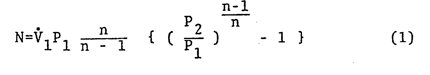

- It can be noted from equation (1) that the power input to the compressor per revolution is proportional to the product of the compressor suction pressure and suction volume. The heat distribution capability of the refrigeration cycle to individual rooms will be discussed in the following for cases of a nominal ambient temperature, a lower ambient temperature, and a higher ambient temperature.
- When the ambient temperature is nominal, the refrigeration cycle would become as depicted in Fig. lb, in which the cross hatched area represents the heat distribution rate of the refrigeration cycle into individual rooms. It is noted in this case that the available .entropy differential of the cycle is fully utilized by the refrigerant.
- However, when the ambient temperature is getting lower, as shown in Fig. la, relative to the nominal temperature, the temperature gradient between the ambient air and the refrigerant becomes too small to fully vaporize the refrigerant in the evaporator at this pressure ratio. The compressor then would intake wet vapor. The corresponding T-S diagram is getting wider in shape, as shown in Fig. la, representing the increased weight flow rate of the refrigerant due to the specific volume decrease of the refrigerant. In this case, however, only a fraction of the entropy differential available for this cycle is utilized and a part of the power input to the compressor is lost to only circulate dummy liquid refrigerant in the refrigeration cycle. The heat distribution rate of the refrigeration cycle into the individual rooms is shown by the cross hatched area in Fig. la and is less than that of Fig. lb shown superimposed on Fig. la by dot and dash lines. In addition, such disadvantages exist that the compressor would intake wet vapor, and the efficiency.of the compressor tends to degrade for this condition.
- The existing heat pump air conditioning system therefore often needs assistance from an auxiliary heat source such as electric resistance heat when the outdoor temperature is getting cold.
- When the ambient temperature is getting high relative to the nominal temperature, as shown in Fig. lc, the temperature gradient between the ambient air and the refrigerant becomes so large that the refrigerant vaporizes fully and are further superheated in the evaporator at this pressure ratio. The corresponding T-S diagram is getting slim in shape as shown.in Fig. lc, representing the reduced weight flow rate of the refrigerant due to the specific volume increase of the refrigerant. The heat distribution rate of the refrigeration cycle into the individual rooms is shown by the cross hatched area in Fig. lc and is less than that of Fig. lb shown by the dot and dash line in Fig. lc. This is apparent from equation (2), since the weight flow rate of the refrigerant W decreases as the absolute temperature of the refrigerant at the compressor inlet Tl. increases while the power N to the compressor is held constant. In addition, the compressor efficiency degrades due to overheating and consequently the useful life time of the compressor would be shortened.
- It is concluded now from the above reasonings and equation (2) that an optimum pressure ratio, or an optimum rotational speed of the compressor should exist for a fixed opening of the expansion valve to maximize the coefficient of performance of the refrigeration cycle, should the temperature difference of the indoor and outdoor environments, and the weight flow rate of the refrigerant be given. It will now be explained in the following that an apparent ambient temperature rises in the heating mode when a solar collector is installed as an outdoor heat exchanger. The heat collection rate per unit area q of the solar collector is given by the following equatrien (3).

- It is assumed that t'1>t1, and the second term of the right side of equation (3) represents the heat loss by convection from the refrigerant to surrounding atmosphere.
- Equation (3) could be converted to as,

- Equating equations (3) and (4), and solving for t1e gives,

- Equation (4) assumes that the amounts of heat transfer as given by equation (3) is made solely by heat convection from a fictitious ambient atmosphere to the refrigerant. Hereafter we call t1e as the effective ambient temparature which is typically higher in value than the ambient temperature and corresponds approximately to the temperature of the solar collector in use. When the solar collector is used, it is apparent from equation (4) that the lower the temperature of the refrigerant, the more heat can be transferred into the system. With this in view, in the present preferred embodiment, a solar radiation energy is collected at a lower temperature by utilizing a latent heat energy of the refrigerant.
- In case of the cooling mode, the night sky radiation is made from the solar collector during clear summer time. The effective ambient temperature tle for this case is similarly defined; i.e., the temperature is typically lower than the ambient temperature and corresponds approximately to the temperature of the solar collector in use. The detailed derivation of the effective-ambient temperature is not given here for the cooling mode.
- Having recognized the fact that the effective ambient temperature is higher (or lower) than the ambient temperature when the solar collector is used, it is necessary to explain the reason why the coefficient of performance improves when the solar collector is used as the "second" heat exchanger.
- Fig. 2 is the T-S diagram of a reverse Carnot cycle of refrigeration which provides the maximum heat transfer capability. Q, and Q2 are the heat transferred into and out of the cycle, respectively. and L is the power input to the reverse Carnot cycle per unit refrigerant weight flow which is indicated in Fig. 2 by the area enclosed by cross hatched lines.
- The following equations define the coefficients of performance φH and φC, respectively for the heating and cooling modes of the reverse Carnot cycle.


- For example, if the coefficient of performance of the existing heat pump air conditioning system with tl=-15°C(Tl=258°K) and t2=35°C (T2=308°K) offers 3.5, then the present invention with the effective ambient temperature of 15°C(T1=288°K) would provide the coefficient of performance of about 8.8. This figure was calculated by substituting the corresponding numerical values of T1 and T2 into equation (6), taking the ratio of the coefficient of performance of the present invention over the existing system, and multiplying the ratio by the coefficient of performance of the existing heat pump air conditioning system, i.e., 3.5. It was assumed that ΔT1=ΔT2=0.
- The T-S diagrams of Figs. 3a and 3b compare the actual refrigeration cycle for the existing heat pump air conditioning system to that of the present invention with solar collector. It is noted from the figure that the power input to the compressor is greatly reduced by using solar radiation for a given heat rejection rate Q2. The power input to the compressor is represented in the T-S diagram by the cross hatched area around which the refrigeration cycle takes place. The T-S diagrams of Figs. 3c and 3d are for cooling mode. The actual refrigeration cycle of the existing heat pump air conditioning system is compared to that of the present invention with solar collector. By utilizing nocturnal cooling, the condensating temperature of the present invention is lowered for a given heat collection rate Ql, compared to the existing system, thus improving the coefficient of performance.
- Whenever either the additional heat source of heat sink is available, the rotational speed of the rotary compressor could be reduced to lower the pressure ratio for a given heat load.
- The preferred embodiment adaptively varies the pressure ratio of the refrigeration cycle in accordance with its environment to improve the coefficient of performance. Turning now to Figs. 4a and 4b wherein a relationship between the pressure ratio and the volumetric flow rate of the refrigerant is illustrated.
- As shown in Fig. 4a, there exists a volumetric flow rate of the refrigerant which would maximize the efficiency of the rotary compressor at. a given pressure ratio. These points for different pressure ratios can be linked together to form the optimum operating line as shown by a dash and dot line in Fig. 4a. To bring- the operating point of the refrigeration cycle on this line, the volumetric flow rate of the refrigerant must be controlled as well as the pressure ratio. Therefore, as illustrated in Fig. 4b, both the rotational speed of a rotary compressor 1 and the opening of a variable expansion valve 3 are continuously controlled on real-time basis. A refrigeration cycle is so realized that the coefficient of performance at a given operating condition approaches or is substantially equal to its maximum valve. In Fig. 4b, the rotational speed of the compressor 1 is varied by a
motor 2 and the opening of the expansion valve 3 is also varied by amotor 4 to obtain the most optimum operating point mentioned above. In this manner, both aheat exchanger 5 on high temperature side and a heat exchanger 6 on low temperature side can be operated in an ideal fashion. - In a conventional heat pump air conditioning system, heat distribution into and heat absorption out of individual rooms is done typically by switching the compressor on and off, because the rotary compressor has a fixed rotational speed and the expansion valve has an almost fixed opening. Therefore, the refrigeration cycle is not optimized in accordance with the temperature difference of indoor and outdoor environments, and a cyclic variation of room temperatures can exist.
- Now, the heat pump air conditioning system of the present invention tries to utilize solar heating and night sky cooling as additional heat transfer means, the temperature of the heated or cooled water in the storage tank is not necessarily constant. The room temperature, however, is desired to be kept at an approximately constant level, so that the temperature gradient varies between the water in the storage tank and the air in the room. This gradient can be compensated for by varying the rotational speed of circulation pump and by metering of individual flow control valve at the inlet of the indoor heat exchanger in each room, thus the fine adjustment of the room temperature can be made individually in response to heat demand of each room, without an on-off control of the compressor.
- In a preferred embodiment of the present invention, efforts have been made to maximize the coefficient. of performance in the upstream of the water storage tank by collecting or dissipating the heat energy as much as possible and in the downstream by properly distributing the heat energy stored in the storage tank to respond to the heat demand from the individual rooms. In this manner, a very efficient heat pump air conditioning system is realized.
- When the ambient temperature is getting lower, the conventional heat pump air conditioning system has such problems as a degradation of the start-up characteristics of the system and a poor heat conduction characteristic of the outdoor heat exchanger due to the accumulation of frost on the surface of heat exchanger, necessitating an intermittent interruption of the heating mode for defrosting, and causing uncomfort to human in the room. These problems are alleviated by the preferred embodiment because a storage tank is installed between the refrigeration cycle and the water distribution network and the open and closed loop control of the refrigeration cycle is performed on a continuous basis.
- Turing now to a block diagram shown in Fig. 5, explanation will be made of the overall arrangement of an embodiment of an air conditioning system according to the present invention.
- "Freon" is used as the refrigerant for this air conditioning system. The
solar collector 30 and the outdoor heat exchanger 32 are connected in parallel. A variablespeed rotary compressor 34 compresses low pressure refrigerant vapor into high pressure vapor, and a variableopening expansion valve 36 controls the pressure differential across thevalve 36 for a given flow rate of the refrigerant. Awater storage tank 38 is thermally insulated and stores heated or cooled water at a preprogrammed temperature which will be explained later. A storagetank heat exchanger 40 is installed inside thewater storage tank 38, and performs heat transfer between the refrigerant and heated or cooled water in thestorage tank 38. - A variable
speed circulation pump 42 takes out heated or cooled water in thestorage tank 38 from awater exit port 44, to conduct the water into the indoor heat exchanger where heat is rejected or absorbed, and returns it back to awater entrance port 48. Areservoir 50 is installed just downstream of the variableopening expansion valve 36 to separate liquid refrigerant from the heat exchanger on a high temperature side from vapor refrigerant not liquefied and to store excess liquid refrigerant which is not in use. - The
reservoir 50 also absorbs, redistributes, and stores excess refrigerant when the operation mode is transferred such as from thesolar collector 30 to the outdoor heat exchanger 32 or from the heating to cooling mode, etc. - The present embodiment has four operational modes; i.e., heating, cooling, solar collector transfer, and outdoor heat exchanger transfer modes of operation.
-
Solenoid valves solar collector 30 or the outdoor heat exchanger 32. Checkvalves 64, 66, 68 and 70 are connected in parallel with thesolenoid valves way valve 72 on the compressor side and a four-way valve 74 on the expansion valve side are to change the flow direction.of the refrigerant in accordance with the heating mode or the cooling mode. - Each room is equipped with a
solenoid valve 78. Whenever the room needs air conditioning, and heated or cooled water is delivered into each room under the command of thesolenoid valve 78 of which position is selected manually by aroom switch 99. Aflow control valve 79 regulates the flow rate of heated or cooled water into each room in accordance with the heat demand of that room. - A solar
collector pressure transducer 80, an outdoor heatexchanger pressure transducer 82, and a storage tank heatexchanger pressure transducer 84 measure the saturated vapor pressure of the refrigerant inside the respective heat exchangers. A variable speed circulationpump pressure transducer 85 measures an outlet pressure of the variablespeed circulation pump 42. These transducers in this embodiment are of strain gauge type and are utilized as safety sensors for overpressurization as well. Thepressure transducer pressure transducer 84 sense high and low saturated evaporating pressures, respectively, which can be translated into the saturated evaporating temperature and saturated condensing temperature as functions of the respective saturated evaporating pressure. - A
temperature sensor 86 on the inlet side of thevariable speed compressor 34 and atemperature sensor 88 on the inlet side of the variableopening expansion valve 36 respectively measure the outlet temperatures of the heat exchangers on a low temperature side and a high temperature side. The temperatures thus measured are then used along with the saturated evaporating temperature mentioned above to calculate the degrees of superheat and subcool which will be described later. - A solar
collector temperature sensor 90 measures the equivalent ambient temperature mentioned earlier, and its output is used with the output of anambient temperature sensor 92, attached to the outdoor heat exchanger 32, to determine if thesolor collector 30 could be used instead of the outdoor heat exchanger 32. - A storage
tank temperature sensor 94 measures the temperature of heated or cooled water in thestorage tank 38, and aroom temperature sensor 96 measures a temperature inside each room. - In the present embodiment, thermister may be used as the temperature sensor. A room
temperature setting dial 98 can be manipulated to preset the room temperature at a . desired level. A roomair conditioning switch 99 controls thesolenoid valve 78 to conduct the heated or cooled water into only desired rooms. - A stepping
motor 100 continuously varies an opening of the variableopening expansion valve 36, and a variablespeed induction motor 102 continuously varies an rotational speed of the variablespeed rotary compressor 34. - Similarly, a stepping
motor 104 and a variablespeed induction motor 106 continuously control an opening of theflow control valve 79 and a rotational speed of the variablespeed circulation pump 44. -
Reference numeral 110 denotes a control unit. In response to the status of the console switches 76 and the data obtained from thevarious pressure transducers control unit 110 performs such functions as the selection of the operation mode, the switching of each valve, the measurement and control of the rotational speed of the variablespeed induction motors opening expansion valve 104. - The
control unit 110 and the associated devices are described in detail in the following by referring to the block diagram of Fig. 6. As shown in the diagram thecontrol unit 110 is located inside the dashed lines and is connected to the associated devices shown located outside the dashed lines. The inputs to thecontrol unit 110 are described first. - For instance, the signal obtained from the
pressure transducer 80 is voltage amplified and impedance transformed by the signal conditioner provided in thepressure transducer 80 and then is transferred to thecontrol unit 110. The signals obtained from other pressure transducers and temperature sensors are similarly processed to be transferred to thecontrol unit 110. These signals are sampled in turn by ananalog multiplexer 120 to be received by a sample-hold 121. Ananalog multiplexer 120 and the sample-hold 121 receive the control signals on acontrol bus 144 from amicroprocessor 126 via an I/O port 124. - LSI (large-scale integrated circuit)6502 may be used as the
microprocessor 126. Aclock generator 127 having a crystal oscillator supplies a predetermined clock signal to themicroprocessor 126. The analog signal from the sample-hold 121 is then transferred to an A/D converter 122 to be transformed to an 8-bit digital signal, and then to be transferred to the I/O port 124. The A/D converter 122 receives the control signal on thedata bus 144 from themicroprocessor 126 via the I/0port 124. 6520 of LSI is used for the I/O port 124. The data received via the I/O port 124 are routed through an 8-bit data bus 140 to RAM 128 for storage. The necessary data stored in theRAM 128 can be accessed by specifying its address from themicroprocessor 126 via a 16-bit address bus 142. The data are sent to themicroprocessor 126 via thedata bus 140 under the direction of a program written and stored on theROM 130. Themicroprocessor 126 performes necessary arithmetic operations. The results of the arithmetic operations are transferred to the individual devices from the I/O port 124 through thedata bus 140. This output operation is performed with the control signals on thecontrol bus 144 which are sent from themicroprocessor 126 to the I/O port 124. The 2714 and 2716 of LSI may be used for theRAM 128 and theROM 130, respectively. - The output signals are processed to be supplied to each control device in the following manner. The driving signals of
thyristors pulse width modulators 150 and 160 of which signals-have variable pulse repetition periods and variable duty cycles. The driving signals of the steppingmotors rectifiers 152 and 162 rectify and smooth out the line voltage to supply outputs thereof to thethyristors pulse width modulators 150 and 160. The variablespeed induction motors motors opening expansion valve 36 and theflow control valve 79. - The operation of the heat pump air conditioning system of the preferred embodiment can be categorized into five groups: (1) selection of either the heating or cooling mode and start-up of the system, (2) selection of either the solar collector or outdoor heat exchanger and the switching therebetween, (3) an open loop control of the system, (4) a closed loop control of the system, and (5) heat distribution and absorption control into and out of each room.
- These operations are further described in the following.
- The manual switches on the operator's
console 76, as shown in Fig. 5, are manipulated to select this system out of heating, cooling, and non-use modes of operation. - Should the heating mode be selected, the four-
way valve 72 on the compressor side and the four-way valve 74 on the expansion valve side are switched to the position as indicated in Fig. 5, and the refrigerant will flow in the direction shown by the solid arrows. This corresponds to the heating mode of operation. For cooling mode, the four-way valves - Whenever the heat pump air conditioning system is started up, the heating mode must be selected first. The
solenoid valves speed rotary compressor 34 is started. - Consequently, residual refrigerant stored in the
solar collector 30 and the outdoor heat exchanger 32 is directed to thereservoir 50 through thecheck valve 74. Since thesolenoid valves 56 and 53 are shut down, the refrigerant will not flow through theexpansion valve 36. Therefore, the pressure inside thereservoir 50 is building up, so that the gaseous refrigerant is being liquefied in thereservoir 50. Here, when a pressure on the high pressure side obtained from the storagetank pressure transducer 84 builds up beyond a predetermined value, a steady operating mode is entered by opening appropriate solenoid valves, depending upon eithersolar collector 30 or outdoor heat exchanger 32 is used. - These operations are performed automatically by the
microprocessor 126 in thecontrol unit 110. - The selection of the heat exchangers and the switching therebetween will be discussed next.
- It is important to determine which one of the
solar collector 30 and outdoor heat exchanger 32 is to be selected for the improvement of the coefficient of performance in both the heating and cooling modes. - Therefore, in order to select either one of the heat exchangers, comparison of the outputs is made between the solar
collector temperature sensor 90 attached to thesolar collector 30 and theambient temperature sensor 92 attached to the outdoor heat exchanger 32 by themicroprocessor 126 in thecontrol unit 110. - The temperature of the
solar collector 30 is increased by solar heating, if it is sunshining during cold winter time. Consequently, the equivalent ambient temperature indicated by the solarcollector temperature sensor 90 is higher than the ambient temperature measured by theambient temperature sensor 92. - On the other-hand, the temperature of the
solar collector 30 is cooled down by the night sky radiation during clear summer time. Therefore, the equivalent ambient temperature indicated by the solarcollector temperature sensor 90 is lower than the ambient temperature measured by theambient temperature sensor 92. - Depending upon whether a temperature difference between the equivalent ambient temperature and the ambient temperature exceeds a predetermined value,.and whether this situation continues for a certain period of time, the two
heat exchangers 30 and 32 would be switched under the control of themicroprocessor 126. This switching, however, has one associated problem in that an amount of refrigerant in the refrigeration cycle tends to decrease, if the refrigerant remains in the unused heat exchanger. - It is desirable, therefore, before the switching of the heat exchangers, to pump out the refrigerant from both the
solar collector 30 and the heat exchanger 32 to recover the refrigerant into thereservoir 50. - Similar procedure as described in the start-up operation is followed for this reason. The heating mode is selected first for the heat pump air conditioning system, the
solenoid valves speed rotary compressor 34 is then started. Consequently, the refrigerant in theheat exchangers 30 and 32 flows through the check valves 68 and 70 via the four-way valve 74 on the expansion valve side into thereservoir 50. - As the pressure in the storage
tank heat exchanger 40 is building up, the gaseous refrigerant Sill be liquefied in thereservoir 50. When the pressure indicated by the storagetank pressure transducer 84 exceeds a preset value, the solenoid valve of the desired heat exchanger is opened to start a steady operation of either heating or colling mode. - Now, the open loop control of the heat pump air conditioning system will be explained.
- A purpose of the open loop control is to give strategies of the collection of external heat or dissipation of internal heat in the form of programmed control of the heat pump air conditioning system. Programmed control of heating and cooling is made based on the prediction of weather and heat load for a relatively long period of time, such as one to several days.
- To satisfy the heat collection or dissipation requirement by utilizing additional heat source or heat sink of solar irradiance or night sky radiation is closely related to maximize the integral coeffic.ient of performance of the system for a period of one to several days.
- However, if the water temperature in the storage tank gets too high (or too low), the heat convection increases from the surface of the storage tank to ambient atmosphere. Therefore, it is necessary to determine the optimum time history of the water temperature in the storage tank, namely, the optimum time history of the heat transfer to or from the storage tank, for a period of one day, for instance. For this purpose, a full-scale experiment and simulation would be necessary using known heat source, heat sink and heat load.
- The details of the program of heat collection or dissipation for maximizing the coefficient of performance is not discussed here. It is noted, however, that the program should consist of a simple control law and it can be updated automatically in a few seconds to adapt promptly to environmental variations.
- Explanation is now made of the operations of the open loop control. To help the understand the operation, the equilibrium condition of a refrigeration cycle is discussed first referring to the first law of thermodynamics. A Match is assumed to exist here between a rotational speed of the compressor and an opening of the expansion valve. How to match these two devices will be discussed later.
- Figs. 7a and 7b show as an example a system diagram and the p-h diagram of an ideal refrigeration cycle for an ideal heating mode. For convenience, the fluid system is subdivided into two open systems as shown in Fig. 7a. The high pressure side is from the inlet 11 of the
compressor 15 to theinlet 13. of theexpansion valve 16. The low pressure side is from theinlet 13 of theexpansion valve 16 to the inlet 11 of thecompressor 15.Reference numeral 12 denotes the outlet of thecompressor expansion valve 16, 17 a condenser, and 13 an evaporator. Since we are dealing with an ideal system, the pressure loss and temperature drop in the pipings, etc. will not be condsidered here. Also the kinetic and potential energies are neglected, since they are smalls - The following equation can be applied to each open system, using the first law of-thermodynamics below.

- When dealing with a steady flow condition, the flow rate of the refrigerant is constant throughout the system, i.e.

- The internal energy of the system U is also constant, consequently,

- To apply equation (3) to the high pressure side of the system, we define the following variables.


- The heat rejection rate mq2 on the right hand side of equation (13) represents the heat transfer from the refrigerant to the water in the storage tank and is a function of the condensing temperature, the rotational speed of the compressor, and the water temperature in the storage tank as shown by the solid lines in Fig. 8a.
- The left hand side of equation (13), on the other hand, implies the compressor work plus the rejecting enthalpy differential and is a function of the condensing temperature and the rotational speed of the compressor as shown by the dashed lines in Fig. 8a. The reason why the dashed lines have positive gradient is explained as fellows. When the condensing temperature increases, the specific enthalpy differential of saturated vapor and saturated liquid (i.e., the width of the saturation line in the p-h diagram) decreases by a little. However, the increase of the weight flow rate m of the refrigerant is dominant, so that the rejecting enthalpy increases. This phenomena are shown in Fig. 7b, where the specific volume of the refrigerant decreases, as the saturated vapor pressure increases, and the weight flow rate m per given rotational rate of the rotary compressor will increase.
- Equation (13) represents thermal -equilibrium and is satisfied at a point that the solid line and the dotted lines cross. Assuming that the water temperature of the storage tank is "medium", then referring to Fig. 8a, point A and point B can be determined as cross points corresponding to Nl and N2 of the rotational speeds of the compressor. The equilibrium line of the system can now be obtained by connecting point A and point B by the dash and dotted line. Similar equilibrium lines can be drawn corresponding to "high" and "low" water temperatures as depicted in Fig. 8a.
- By using this equilibrium line, it is noted that the equilibrium point of rejecting energy rate Q2 drops from point A to point C, when the water temperature and the rotational speed of the compressor vary from "medium" to "high", and from N1 to N2, respectively. When this drop happens, the corresponding compressor work plus rejecting enthalpy also drops from point A to point C, resulting in lowering the weight flow rate m, i.e., the rotational speed of the compressor.
- Referring to Fig. 8a, it is understood that if the rejecting energy Q2 is given as a function of the rotational speed of the compressor and the water temperature of the storage tank, then the corresponding condensating temperature of the refrigerant is determined automatically. In other words, if two out of four variables are given, the remaining two variables are automatically determined.
- Now, let equation (8) be applied to the lower pressure side of the system by assuming:

- Then the following equation is obtained by referring to Fig. 7b:

- When the heat rejection rate Q2 to the water storage tank in the high pressure side is determined and the rotational speed of the compressor, or the associated work W2 is known, then the heat collection rate Qlin the low pressure side can be obtained by the following equation referring to Fig. 7b.

- Equation (16) represents the heat collection rate Ql=mql in equation (15) and implies the heat transfer from the equivalent ambient atmosphere or ambient atmosphere to the refrigerant. The heat collection rate Q, is given as a function of the evaporating temperature, rotational speed of the compressor and the (equivalent) ambient temperature, as depicted by the solid lines in Fig. 8b. The left hand side of equation (15), on the other hand, represents the gained enthalpy and is obtained as a function of the evaporating temperature and the rotational speed of the compressor as depicted by the dashed lines in Fig. 8b. The reason why this graph has a positive gradient is the same as that already explained for the high pressure side of the system.
- Assume now that the equivalent ambient temperature changes abruptly from "low" to "high", when the heat collection rate Q1, corresponding to the value given by abscissa of point D in Fig. 8b, is required. The evaporating temperature of equilibrium then shifts from the value given by ordinate of point D to point E to obtain the same amount of heat energy. The transfer of the heat equilibrium point from point,D to point E implies that reduced rotational speed (N3 in this case) of the compressor compared to the original speed of N1 can produce the same amount of enthalpy differential since the specific volume of the refrigerant reduces as the evaporating temperature increases. In other words, if a variable speed compressor is used, the input power to the induction motor of the compressor can be reduced, since the driving power of the compressor is proportional to the rotational speed. If a variable torque rotary compressor is used, a smaller amount of input power is sufficient to the induction motor of the compressor per motor revolution, since the torque load of the compressor is reduced in accordance with reduced pressure differential in the refrigeration cycle. It is, therefore, understood from Fig. 8b that less power consumption is achieved when the solar heating is used, relative to the case without the solar heating, since the equivalent ambient temperature is increased to obtain the same amount of heat.
- Above discussion has assumed that a match exists between the rotational speed of the compressor and the opening of the expansion valve. We will discuss now how to match these two devices in the following.
- When the rotational speed of the compressor is given, the volumetric flow rate of the refrigerant through the compressor can be obtained. As the specific volume of the refrigerant at the inlet port of the compressor is known, the weight flow rate m of the refrigerant can be calculated using the known compressor inlet temperature. When the saturated condensing temperature and the evaporating temperature of the refrigerant are known, the saturated vapor pressure P2 on the high pressure side and the saturated vapor pressure p1 on the low pressure side can be determined as shown in Fig. 7b.
- Assuming that both sides of the expansion valve are filled with liquid, then the opening Al of the expansion valve must satisfy the following equation of throttling for an isenthalpic flow.

- In an actual expansion valve, however, a part of the refrigerant is already vaporized due to temperature decrease caused by the throttling. Now if it is assumed that the pressure ratio of the high pressure side to the low pressure side is more than twice, and that the nozzle throat area and the low pressure side are filled with a gaseous fluid only, then the opening A2 of the expansion valve must satisfy the following equation of critical flow of gas.

- In the actual expansion valve, however, the mixture of the refrigerant in its liquid and vapor phases exists of which flow is governed by both equations (17) and (18). The two phases are considered to be intermixing and having friction with each other. In summary, if the rotational speed-of the compressor is given for a specific condition, the weight flow rate of the refrigerant can be calculated at the inlet of the compressor, and the corresponding opening A of the expansion valve can be determined as a matched set from equations (17) and (18) or from experimental results. When the two devices are mismatched, the efficiency of the refrigeration cycle is lowered as indicated in Fig. 4a.
- As mentioned earlier in relation to Figs. 8a and 8b, the rotational speed of the compressor and the opening of expansion valve are determined when the rejecting heat energy is given in accordance with the water temperature of the storage tank and the equivalent ambient temperature or the ambient temperature. The saturated condensing temperature and the saturated evaporating temperature are also determined and the high and low saturated vapor pressures of the present heat pump air conditioning system accordingly. Therefore, the relation mentioned above can be stored in the
ROM 130 of thecontrol unit 110 as a graphical form such as shown in Fig. 9 or a simple approximate formula such as a quadratic equation of which coefficients can be obtained from results of full-size experiment and/or simulation. The graph shown in Fig. 9 is stored in theROM 130 and gives approximate values of the rotational speed y, of the variablespeed rotary compressor 34 and the opening Y2 of the variable opening expansion valve, should the temperature difference between the water in the storage tank and the (equivalent) ambient temperature be known and the heat rejection rate to the storage tank be also given. This is a programmed control based on experimental results only and it is an open loop control which does not need a feedback of the state variables. - The open loop control is now described in detail by referring to Fig. 6.
- The values y, and y2 read from the
ROM 130 are transformed into appropriate signal forms to be received by thepulse width modulator 150 and the pulse generator 170, respectively, and then are transferred through the I/0port 124. The output from thepulse width modulator 150 is supplied to thethyristors 154, where the dc current is chopped to control the rotational speed of the variablespeed induction motor 102. Therectifier 152 is installed to rectify and smooth out the line voltage to obtain a dc voltage which is supplied to thethyristors 154. The output of the pulse generator 170 is supplied to the steppingmotor 100 to control the opening of the variableopening expansion valve 36. - To adapt the system to external atmospheric variations, an update is made, for example, once in five minutes to obtain an optimum heat rejection rate to the water in the
storage tank 38. Rescheduling is made for both the rotational speed of the variablespeed rotary compressor 34 and the opening of the variableopening expansion valve 36. This action is referred to as a major cycle compared to a minor cycle which will be described later. - One of salient features of this system is a control of the amount of heat collection or dissipation rate which has been difficult in the past. As apparent from Fig. 9, the amount is controlled by varying both the rotational speed of the compressor and the opening of the expansion valve in accordance with the temperature difference between the water temperature of the storage tank and the (equivalent) ambient temperature. The discussion thus far are focused primarily on the heating mode of operation. But it can be easily extended to the cooling mode as well.
- The above process of the open loop control is explained by using a flow chart of Fig. 10. First, step 1 checks whether the refrigeration cycle is to be stopped or not. Whenever the
console switch 76 in. Fig. 5 is "ON", step S2 is entered. Otherwise, step S10 is selected and the sequential control is initiated to stop the system and the refrigeration cycle is eventually halted. - Step S2 measures the water temperature of the
storage tank 38 by thetemperature sensor 94, and the equivalent ambient temperature by the solarcollector temperature sensor 90 or the ambient temperature by theambient temperature sensor 92. Step S3 checks whether the switching of heat exchangers and accompanying open loop cotrol is necessary based upon the measured temperature difference between thecollector temperature sensor 90 and theambient temperature sensor 92. If it is determined that the switching is necessary, then step S4 is initiated to sequentially control the switching of heat exchangers. Otherwise, step S9 is entered and the closed loop control is to take place. - Step S5 then calculates the heat rejection or collection rate to or from the
storage tank 38 by an optimization program. Step S6 reads data from the table lookup on theROM 130 to calculate the rotational speed of thecompressor 34 and the opening of theexpansion valve 36. The calculation is based upon the temperature difference between the water temperature in thestorage tank 38 and the (equivalent) ambient temperature, and the heat rejection or collection rate. Step S7 reads data from the table lookup on theROM 130 concerning the rotational speed y1 of thecompressor 34 and the opening Y2 of theexpansion valve 36. The values y1 and Y2 are then transformed into appropriate signal forms to be supplied to thepulse width modulator 150 and the pulse generator 170 via I/0port 124. In step S8, the rotational speed of the variablespeed induction motor 102 and the opening of theexpansion valve 36 are controlled by thepulse width modulator 150 via thethyristors 154, and the pulse generator 170 via the steppingmotor 100, respectively. - The closed loop control is now described for the heat pump air conditioning system of the present invention.
- The open loop control just mentioned above controls both the pressure ratio and the volumetric flow rate based on prediction to bring both of them on or near the optimum operating line of Fig. 4a. This programmed control of the heat rejection to or collection from the storage tank is made in relation to the heat demand and weather and heat load prediction for a relatively long period of time.
- By this control, the refrigeration cycle of the present air conditioning system becomes close to the ideal refrigeration cycle mentioned earlier in the diagrams of Fig. 1 and Fig. 3. The closed loop control tries to bring the refrigeration cycle of the present system to further coincide with the ideal cycle in order to maximize the coefficient of performance at the present operating point. The degrees of superheat and subcool are regarded as two major dependent state variables and the deviations of which from the ideal values are used as feedback signals in the closed loop control system. Fine-control is made on the two independent control variables, i.e., the rotational speed of the compressor and the opening of the expansion valve. The degree of superheat is defined as the temperature difference between the temperature of the refrigerant at the compressor inlet and its saturated evaporating temperature in the evaporator, and the degree of subcool is defined as the temperature difference between the temperature of the refrigerant at the expansion vavle inlet and its saturated condensing temperature in the condenser.
- The degrees of superheat and subcool of the refrigerant are explained in Fig. 11 by using the p-h diagram.
- Fig. 11 shows an ideal refrigeration cycle by a bold solid line, lines of constant specific volume by dashed lines, and isothermal lines by dash and dotted lines. Consider the steady state refrigeration cycle in a case where the opening of the expansion valve is relatively small with regard to a constant rotational speed of the compressor. The amount of the refrigerant supplied from the expansion valve to the evaporator is less than those intaken by the compressor from the evaporator, and the internal energy in the evaporator decreases and so does the saturated evaporating temperature. As a result, the refrigerant in the evaporator is superheated due to an increase of the collected heat energy. An ideal equilibrium point A at the compressor inlet would then shift to point B as illustrated in Fig. 11. The specific volume of the refrigerant thus increases to result in the decrease of the weight flow rate of the refrigerant through the compressor at a constant speed, thereby attaining a new equilibrium condition. Therefore, the efficiency of the refrigeration cycle decreases, since the weight flow rate obtainable by the rotational speed of the compressor is less than the maximum.
- Consider next the refrigeration cycle in a case when the opening of the expansion valve is relatively-large with regard to a constant rotational speed of the compressor. The amount of the refrigerant supplied to the evaporator now increases to raise the evaporating temperature and to decrease the heat energy collected. The evaporator then tends to be filled with the liquid refrigerant, and the ideal equilibrium point A moves to point C. The specific volume of the refrigerant thus decreases resulting in the increase of the weight flow rate of the refrigerant, so that the amount of the refrigerant taken into the compressor balances with the amount of the refrigerant supplied by the expansion valve. However, the latent heat associated with this refrigeration cycle is not fully utilized, so that the heat collection capability of the system at the equilibrium condition and consequently the coefficient of performance thereof decreases.
- From the discussion above, there exists an optimum degree of superheat in the heat pump air conditioning system to maximize its coefficient of performance. This condition can be satisfied by controlling relative magnitudes of the rotational speed of the compressor and the opening of expansion valve. This explanation can be applied to the equilibrium condition at the inlet of the expansion valve (point D in Fig. 11) as well, and there exists an optimum degree of subcool there. Like in the case of superheat, this condition can also be satisfied by controlling relative magnitudes of the rotational speed of the compressor and the opening of the expansion valve.
- It will be explained in the following referring to the flow chart of Figs. 12a and 12b how this closed loop control is performed of the rotational speed of the
compressor 34 and the opening of theexpansion valve 36 to optimize the degrees of superheat and subcool. - The computational sequence of step S9 in Fig. 10 is succeeded by step S13 via step S12 of Fig. 12a. Step S13 checks whether the refrigeration cycle is stopped or not. If the refrigeration cycle is not to be stopped, step S14 is entered. Otherwise, step S24 is initiated, so that the sequential control is performed to stop the system, and the refrigeration cycle is eventually halted. Next, in step S14, the saturated evaporating pressure p1 and the saturated condensing pressure p2 are measured by the
pressure transducers pressure transducer 84, respectively, to be stored temporarily in theRAM 128 of thecontrol unit 110. The following functional relations, in equations (19), are defined a priori which relate the saturated evaporating temperature t10 and the saturated condensing temperature t20 to functions of the saturated evaporating pressure p1 and the saturated condensing pressure p2, respectively:
ROM 130 as a table lookup on which the saturated evaporating temperature t10 and the saturated condensing temperature t20 are defined to relate to the corresponding pressures p, and P2 as numerical sets. By using the pressures p1 and p2 measured and stored in theRAM 128, the saturated evaporating temperature t10 and the saturated condensing temperature t20 are calculated by interpolation or extrapolation of the stored values. - The inlet temperature t1 of the variable
speed rotary compressor 34 and the inlet temperature t2 of the variableopening expansion valve 36 are respectively measured by thetemperature sensors RAM 128. If we denote the degrees of superheat and subcool at present as Δt1 and Δt2, respectively, then these can be defined by the following forms using the data obtained above (step 15):
- Denoting the degrees of superheat and subcool of the ideal condition as Δt10 and Dt20, respectively, the deviations of the degrees of superheat xi and subcool x2 from an ideal condition can be calculated by the
microprocessor 126 as follows in step S16:
speed rotary compressor 34 and a fine adjustment Δy2 of the opening of the variableopening expansion valve 36 are defined, respectively, to relate linearly to the deviations of degree of superheat x1 and degree of subcool x2 as functions of the saturated evaporating temperature t10 and the saturated condensing temperature t20 by using the following sensitivity coefficients.
- Therefore, xi amd x2 have the following linear relations to Δy1 and AY2 which is shown in step S17:


bc ≠ 0. - If ad-bc=0, the calculation of equations (23) is skipped. Fine adjustment of the rotational speed Δy1 of the variable speed rotary compressor and the opening Δy2 of the variable opening expansion valve are calculated by the
microprocessor 126 using the sensitivity coefficients a, b, c and d and the deviations of the degrees of superheat xi and subcool x2 in step S18. - Δy1 and Δy2 thus obtained are transformed into appropriate signal forms to be supplied to the
pulse width modulator 150 and the pulse generator 170, respectively. These signals are transferred from themicroprocessor 126 to thepulse width modulator 150 and the pulse generator via the I/O port 124 (step S19). In step S20, the output from thepulse width modulator 150 controls finely the opening ofexpansion valve 36 via the steppingmotor 100. This calculation and the control are performed once in every thirty seconds to one minute, which is referred to as the minor cycle. Step S21 checks whether the period of closed loop control elapsed or not. If the elapse is judged, then step S22 is entered. If not, step S21 is repeated until the elapse is judged. Similar to step S21, step S22 checks whether the period of open loop control is elapsed or not. If the elapse is not judged, the sequence returens to step S13. Otherwise, step Sll of the open loop control shown in Fig. 10 is reentered via step S23 to repeat the open loop control. In the cooling mode, almost the same control of the refrigeration cycle is performed as in the heating mode. Hence, further explanation will be omitted here. - In summary, an active control of the heat rejection to and collection from the water storage tank is performed in the above-described two sequences. First, in the open loop control, the magnitude of the pressure differential between the high and low saturated vapors of the refrigeration cycle is determined based on the temperature difference between the water in the storage tank and the equivalent ambient temperature or the ambient temperature, and the heat transfer rate to or from the storage tank. The corresponding rotational speed of the compressor and the opening of the expansion valve are then approximately obtained. Next, in the closed loop control, the rotational speed of the compressor and the opening of the expansion valve are controlled finely to adapt the present degrees of superheat and subcool to those of the ideal refrigeration cycle. An ideal refrigeration cycle is thus realized by the present embodiment of refrigeration cycle.
- Should the pressure differential between the high and low saturated vapors on the p-h diagram and accordingly the rotational speed of compressor is adequately set in accordance with the surrounding conditions and also a match exists between the rotational speed of the compressor and the opening of the expansion vavle, the high and low saturated vapor pressures, or the saturated condensing and evaporating temperatures as a pair shift up and down automatically on the p-h refrigeration diagram until they settle down on an equilibrium condition, in response to the heat input and output rate.
- Thus, the heat pump air conditioning system of the present invention can be regarded as an adaptive model follower system which seeks an ideal model of the refrigeration cycle on the p-h diagram.
- The indoor heat distribution and absorption control is explained now with reference to Figs. 5, 6 and 13. The necessity of air conditioning for a particular room is dictated by the
manual switch 99 located in that room, so that the solenoid'valve is either switched on or off. When theswitch 99 is turned on, the two step temperature control, i.e., an initial setting and a steady state regulation are performed to bring the room temperature θ1 to coincide with a desired temperature θ0 preset by theroom temperature indicator 98. - During a predetermined time interval from an instant that the
manual switch 99 is on, the opening of theflow control valve 79, located in each room, is determined in the following manner. An initial opening Y3 of theflow control valve 79 is determined by the following function based on a desired temperature θ0 of theroom temperature indicator 98, a present room temperature 81, and a water temperature θ2 of the water in thestorage tank 38.
ROM 130, to be referred to for necessary computation performed on the data by themicroprocessor 126. - The steady state regulation, after the initial setting, is performed as shown in the block diagram of Fig. 13. This closed loop control has the same sampling period as that of the minor cycle previously described. The
microprocessor 126 in thecontrol unit 110 performs the arithmetic operation shown in Fig. 13. - The present room temperature θ1 is measured by the
room temperature sensor 96. The rate of variation1 of the present room temperature θ1 is calculated by the
microprocessor 126 from the past and present room temperatures. The past room temperatures measured by theroom temperature sensor 96 are stored temporarily in theRAM 128 of thecontrol unit 110. - The present room temperature θ1 and the rate of variation1 are respectively multiplied by the gains K1 and K21 and then added together. The result of the addition is in turn subtracted from the desired room temperature θ0 to obtain a temperature error Δθ. Based upon this resultant error A6, the opening y3 of the
flow control valve 79 is calculated as a function of Δθ. The above process can be expressed by the following equations.

microprocessor 126. There can exist a variable heat gradient At between the desired temperature θ0 set by theroom temperature indicator 98 and the water temperature θ2 of water in thestorage tank 38. Namely,
ROM 130 as a table lookup of which magnitudes are varied continuously as a function of the heat gradient At. - The opening y3 of the
flow control valve 79 is transformed into an appropriate signal form which is supplied to the pulse generator 180 via the I/O port 124. The output of the pulse generator 180 is supplied to the steppingmotor 106 to control the opening of theflow control valve 79. - While the circulation rate of the water flow passing through the variable
speed circulation pump 42 varies depending upon the air conditioning demand of each room, the outlet pressure of the variablespeed circulation pump 42, which is measured by the variable speed circulationpump pressure transducer 42, is kept approximately constant by controlling the rotational speed of the variablespeed induction motor 104 via the pulse width modulator 160 and thethyristors 164. The rectifier 162 converts the line voltage into a direct current to be supplied to thethyristors 164. - The following advantageous effects can be achieved by a heat pump air conditioning system according to the present invention.
-
- (1) The coefficient of performance is greatly improved by controlling the rotational speed of the compressor and the opening of the expansion valve so as to follow an ideal refrigeration cycle.
- (2) The coefficient of performance is further improved compared to a prior art heat pump air conditioning system by installing a solar collector and an outdoor heat exchanger in parallel so that their use is switched in a manner to utilize additional solar heat energy or nocturnal radiation energy, and then by controlling the rotational speed of the compressor and the opening of the expansion valve so as to follow an ideal refrigeration cycle.
- (3) The solar collector and the heat pump air conditioning system are integrally assembled, so that a heat exchanger and a circulation pump which are otherwise necessary to connect the two components in a prior art solar assisted heat pump air conditioning system are not required to realize the present system.
- (4) The system size is small and the components of the existing heat pump air conditioning system and solar thermal heating system can be utilized as is or with minor modifications. Therefore, the initial investment cost for the system is minimal.
- (5) It is not necessary to design an air conditioning system based on the peak heat load, because the system has the storage tank. The peak heat load during winter time can also be overcome by an overdriving the variable speed compressor by a little. This fact, coupled with the advantage of using latent heat, causes the total system to be small-sized.
- (6) Since Freon is used as the refrigerant, the freezing temperature of the refrigerant is low, so that there is no freezing problem as in the case of the hydronic system which often destructs the heat exchanger and pipings.
- (7) No uncomfort problems exist with frosting, since the heat pump is arranged on the upstream side of the water storage tank.
- (8) The system is applicable to the case where the temperature difference of indoor and outdoor environments is large, by either preheating the outdoor heat exchanger using the water in the storage tank, installing a heat pump with a variable speed compressor on the downstream side of the water storage tank, or a combination thereof.
- (9) Since the heat collecting temperature of the refrigerant in the solar collector can be set considerably lower compared with the prior art solar assisted heat pump system, the heat transfer from the ambient atmosphere can be utilized in some cases in addition to the solar radiation.
- (10) An amount of heat collected per unit weight of the refrigerant is very large, because the present system utilizes the latent heat of the refrigerant, while the prior art solar assisted heat pump system uses the sensible heat. Also there is little heat loss along the pipings because of low temperature. Therefore, very efficient heat collection can be realized even though the solar collector is small in size and simple in construction.
- (11) The solar collector is converted into a heat dissipator during summer night time. In this case, high efficiency heat dissipation can be realized, since the condensing temperature of the refrigerant can be lowered because of the colder temperature of the solar collector board.
- (12) Night sky cooling can use lower off-peak electric rate during night time.
- (13) There exists further energy saving measures, since each heat exchanger in each room can be individually operated in response to the heat demand of the individual room.
- (14) The air conditioning of each room is made by linear control of the flow control valve to follow a preset temperature of each room. Therefore, there is no temperature cycling as in the conventional on-off control system, and consequently the system provides comfort to human in the room.
Claims (22)
Priority Applications (1)
| Application Number | Priority Date | Filing Date | Title |
|---|---|---|---|
| AT82106126T ATE17164T1 (en) | 1981-07-10 | 1982-07-08 | AIR CONDITIONING WITH HEAT PUMP. |
Applications Claiming Priority (2)
| Application Number | Priority Date | Filing Date | Title |
|---|---|---|---|
| JP106893/81 | 1981-07-10 | ||
| JP56106893A JPS588956A (en) | 1981-07-10 | 1981-07-10 | Heat pump type air conditioner |
Publications (2)
| Publication Number | Publication Date |
|---|---|
| EP0069996A1 true EP0069996A1 (en) | 1983-01-19 |
| EP0069996B1 EP0069996B1 (en) | 1985-12-27 |
Family
ID=14445145
Family Applications (1)
| Application Number | Title | Priority Date | Filing Date |
|---|---|---|---|
| EP82106126A Expired EP0069996B1 (en) | 1981-07-10 | 1982-07-08 | Heat pump air conditioning system |
Country Status (5)
| Country | Link |
|---|---|
| US (1) | US4420947A (en) |
| EP (1) | EP0069996B1 (en) |
| JP (1) | JPS588956A (en) |
| AT (1) | ATE17164T1 (en) |
| DE (1) | DE3268112D1 (en) |
Cited By (11)
| Publication number | Priority date | Publication date | Assignee | Title |
|---|---|---|---|---|
| EP0138094A2 (en) * | 1983-10-01 | 1985-04-24 | Asea Brown Boveri Aktiengesellschaft | Refrigerator |
| EP0146486A2 (en) * | 1983-12-19 | 1985-06-26 | Carrier Corporation | Method and apparatus for controlling a refrigerant expansion valve in a refrigeration system |
| EP0147357A2 (en) * | 1983-12-22 | 1985-07-03 | Carrier Corporation | Refrigeration system and incrementally adjustable electronic expansion valve |
| EP0147356A2 (en) * | 1983-12-22 | 1985-07-03 | Carrier Corporation | A control system for an electronic expansion valve in a refrigeration system |
| EP0148102A2 (en) * | 1983-12-19 | 1985-07-10 | Carrier Corporation | Method and apparatus for controlling refrigerant flow in a refrigeration system |
| FR2562644A1 (en) * | 1984-04-09 | 1985-10-11 | Alberti Rosette | Operating method for a heat-pump installation and heat pump implementing the method |
| EP0380615A1 (en) * | 1988-06-10 | 1990-08-08 | Honeywell Inc | A method for the optimal comfort and efficiency control of variable speed heat pumps and air conditioners. |
| EP2261574A1 (en) * | 2008-02-29 | 2010-12-15 | Hitachi Appliances, Inc. | Heat-pump hot water apparatus |
| WO2011041408A3 (en) * | 2009-09-29 | 2011-07-21 | Carrier Corporation | System and method for maintaining air temperature within a building hvac system |
| CH708152A1 (en) * | 2013-06-12 | 2014-12-15 | Horst Grüning | Device for continuous adjustment of the output power of an inverter heat pump. |
| EP2495502A4 (en) * | 2009-10-27 | 2015-03-18 | Mitsubishi Electric Corp | Air conditioning device |
Families Citing this family (107)
| Publication number | Priority date | Publication date | Assignee | Title |
|---|---|---|---|---|
| JPS59129034U (en) * | 1983-02-10 | 1984-08-30 | 株式会社東芝 | Cooling operation control device for air conditioners |
| US5177972A (en) * | 1983-12-27 | 1993-01-12 | Liebert Corporation | Energy efficient air conditioning system utilizing a variable speed compressor and integrally-related expansion valves |
| JPS60140075A (en) * | 1983-12-28 | 1985-07-24 | 株式会社東芝 | Method of controlling refrigeration cycle |
| US4549404A (en) * | 1984-04-09 | 1985-10-29 | Carrier Corporation | Dual pump down cycle for protecting a compressor in a refrigeration system |
| US4809516A (en) * | 1984-07-27 | 1989-03-07 | Uhr Corporation | Residential heating cooling and energy management system |
| US4685307A (en) * | 1984-07-27 | 1987-08-11 | Uhr Corporation | Residential heating, cooling and energy management system |
| US4909041A (en) * | 1984-07-27 | 1990-03-20 | Uhr Corporation | Residential heating, cooling and energy management system |
| JPS6162746A (en) * | 1984-08-31 | 1986-03-31 | Matsushita Electric Ind Co Ltd | Cooling, heating and hot water feeding device |
| DE3601817A1 (en) * | 1986-01-22 | 1987-07-23 | Egelhof Fa Otto | CONTROL DEVICE FOR THE REFRIGERANT FLOW FOR EVAPORATING REFRIGERATION SYSTEMS OR HEAT PUMPS AND EXPANSION VALVES ARRANGED IN THE REFRIGERANT FLOW |
| US4718248A (en) * | 1986-05-05 | 1988-01-12 | Stephen Fisher | Four element refrigeration heat pump and geothermal control systems |
| CA1315999C (en) * | 1986-10-31 | 1993-04-13 | John M. Palmer | Refrigerant metering in a variable flow system |
| JPH0718938Y2 (en) * | 1987-01-30 | 1995-05-01 | 株式会社東芝 | air conditioner |
| US5361215A (en) | 1987-05-27 | 1994-11-01 | Siege Industries, Inc. | Spa control system |
| US6965815B1 (en) | 1987-05-27 | 2005-11-15 | Bilboa Instruments, Inc. | Spa control system |
| JPH01306758A (en) * | 1988-06-06 | 1989-12-11 | Matsushita Refrig Co Ltd | Coolor-heater |
| CA1322858C (en) * | 1988-08-17 | 1993-10-12 | Masaki Nakao | Cooling apparatus and control method therefor |
| US5052186A (en) * | 1990-09-21 | 1991-10-01 | Electric Power Research Institute, Inc. | Control of outdoor air source water heating using variable-speed heat pump |
| DE69708319T2 (en) * | 1996-05-22 | 2002-08-22 | Ingersoll Rand Co | DETECTION METHOD FOR PUSH-IN SHOCK IN TURBO COMPRESSORS |
| US5735134A (en) * | 1996-05-30 | 1998-04-07 | Massachusetts Institute Of Technology | Set point optimization in vapor compression cycles |
| US5873257A (en) * | 1996-08-01 | 1999-02-23 | Smart Power Systems, Inc. | System and method of preventing a surge condition in a vane-type compressor |
| ITMI980879A1 (en) * | 1998-04-24 | 1999-10-24 | De Longhi Spa | MACHINE FOR THE PRODUCTION OF HOT OR COLD WATER OR AIR BY MEANS OF A REFRIGERANT FLUID |
| US6505475B1 (en) * | 1999-08-20 | 2003-01-14 | Hudson Technologies Inc. | Method and apparatus for measuring and improving efficiency in refrigeration systems |
| US6691526B2 (en) * | 2000-03-09 | 2004-02-17 | Gether As | Method and apparatus for heating and cooling of buildings |
| US6536677B2 (en) * | 2000-06-08 | 2003-03-25 | University Of Puerto Rico | Automation and control of solar air conditioning systems |
| US6539738B2 (en) | 2000-06-08 | 2003-04-01 | University Of Puerto Rico | Compact solar-powered air conditioning systems |
| US6601397B2 (en) | 2001-03-16 | 2003-08-05 | Copeland Corporation | Digital scroll condensing unit controller |
| US6668240B2 (en) | 2001-05-03 | 2003-12-23 | Emerson Retail Services Inc. | Food quality and safety model for refrigerated food |
| US6892546B2 (en) | 2001-05-03 | 2005-05-17 | Emerson Retail Services, Inc. | System for remote refrigeration monitoring and diagnostics |
| GB2381859C (en) * | 2001-08-29 | 2005-05-27 | Polypipe Building Products Ltd | Control apparatus |
| US6889173B2 (en) * | 2002-10-31 | 2005-05-03 | Emerson Retail Services Inc. | System for monitoring optimal equipment operating parameters |
| US7290398B2 (en) | 2003-08-25 | 2007-11-06 | Computer Process Controls, Inc. | Refrigeration control system |
| US20050103035A1 (en) * | 2003-11-19 | 2005-05-19 | Massachusetts Institute Of Technology | Oil circulation observer for HVAC systems |
| KR100535674B1 (en) * | 2004-02-25 | 2005-12-09 | 엘지전자 주식회사 | 4-way valve control method for multi-heat pump |
| US7412842B2 (en) | 2004-04-27 | 2008-08-19 | Emerson Climate Technologies, Inc. | Compressor diagnostic and protection system |
| US7716943B2 (en) * | 2004-05-12 | 2010-05-18 | Electro Industries, Inc. | Heating/cooling system |
| US20080098760A1 (en) * | 2006-10-30 | 2008-05-01 | Electro Industries, Inc. | Heat pump system and controls |
| US7275377B2 (en) | 2004-08-11 | 2007-10-02 | Lawrence Kates | Method and apparatus for monitoring refrigerant-cycle systems |
| DE602005018669D1 (en) * | 2004-09-30 | 2010-02-11 | Danfoss As | MODEL FORECASTING-CONTROLLED COOLING SYSTEM |
| EP1659349A1 (en) * | 2004-11-22 | 2006-05-24 | Nederlandse Organisatie voor toegepast-natuurwetenschappelijk Onderzoek TNO | Refrigeration or cooling system |
| ATE553422T1 (en) | 2005-02-21 | 2012-04-15 | Computer Process Controls Inc | CONTROL AND MONITORING SYSTEM FOR COMPANIES |
| US6990826B1 (en) * | 2005-04-05 | 2006-01-31 | Carrier Corporation | Single expansion device for use in a heat pump |
| JP3945520B2 (en) * | 2005-05-24 | 2007-07-18 | ダイキン工業株式会社 | Air conditioning system |
| US7752854B2 (en) | 2005-10-21 | 2010-07-13 | Emerson Retail Services, Inc. | Monitoring a condenser in a refrigeration system |
| US7594407B2 (en) | 2005-10-21 | 2009-09-29 | Emerson Climate Technologies, Inc. | Monitoring refrigerant in a refrigeration system |
| US7596959B2 (en) | 2005-10-21 | 2009-10-06 | Emerson Retail Services, Inc. | Monitoring compressor performance in a refrigeration system |
| US7752853B2 (en) | 2005-10-21 | 2010-07-13 | Emerson Retail Services, Inc. | Monitoring refrigerant in a refrigeration system |
| US7665315B2 (en) | 2005-10-21 | 2010-02-23 | Emerson Retail Services, Inc. | Proofing a refrigeration system operating state |
| US8590325B2 (en) | 2006-07-19 | 2013-11-26 | Emerson Climate Technologies, Inc. | Protection and diagnostic module for a refrigeration system |
| US20080216494A1 (en) | 2006-09-07 | 2008-09-11 | Pham Hung M | Compressor data module |
| US8672733B2 (en) | 2007-02-06 | 2014-03-18 | Nordyne Llc | Ventilation airflow rate control |
| US20090037142A1 (en) | 2007-07-30 | 2009-02-05 | Lawrence Kates | Portable method and apparatus for monitoring refrigerant-cycle systems |
| US9140728B2 (en) | 2007-11-02 | 2015-09-22 | Emerson Climate Technologies, Inc. | Compressor sensor module |
| US20100204838A1 (en) * | 2009-02-12 | 2010-08-12 | Liebert Corporation | Energy efficient air conditioning system and method utilizing variable capacity compressor and sensible heat ratio load matching |
| US8616323B1 (en) | 2009-03-11 | 2013-12-31 | Echogen Power Systems | Hybrid power systems |
| EP2419621A4 (en) | 2009-04-17 | 2015-03-04 | Echogen Power Systems | System and method for managing thermal issues in gas turbine engines |
| US8473106B2 (en) * | 2009-05-29 | 2013-06-25 | Emerson Climate Technologies Retail Solutions, Inc. | System and method for monitoring and evaluating equipment operating parameter modifications |
| BRPI1011938B1 (en) | 2009-06-22 | 2020-12-01 | Echogen Power Systems, Inc | system and method for managing thermal problems in one or more industrial processes. |
| US9316404B2 (en) | 2009-08-04 | 2016-04-19 | Echogen Power Systems, Llc | Heat pump with integral solar collector |
| US20110030404A1 (en) * | 2009-08-04 | 2011-02-10 | Sol Xorce Llc | Heat pump with intgeral solar collector |
| US8869531B2 (en) | 2009-09-17 | 2014-10-28 | Echogen Power Systems, Llc | Heat engines with cascade cycles |
| US8794002B2 (en) | 2009-09-17 | 2014-08-05 | Echogen Power Systems | Thermal energy conversion method |
| US8813497B2 (en) | 2009-09-17 | 2014-08-26 | Echogen Power Systems, Llc | Automated mass management control |
| US8613195B2 (en) | 2009-09-17 | 2013-12-24 | Echogen Power Systems, Llc | Heat engine and heat to electricity systems and methods with working fluid mass management control |
| JP2011094810A (en) * | 2009-09-30 | 2011-05-12 | Fujitsu General Ltd | Heat pump cycle apparatus |
| JP5427563B2 (en) * | 2009-11-20 | 2014-02-26 | 三菱重工業株式会社 | Inverter turbo refrigerator performance evaluation system |
| TWI452247B (en) * | 2009-12-09 | 2014-09-11 | Univ Far East | Intelligent heat pump frequency control module and the use of the module heat pump |
| WO2011080800A1 (en) * | 2009-12-28 | 2011-07-07 | ダイキン工業株式会社 | Heat pump system |
| WO2012036855A1 (en) * | 2010-09-13 | 2012-03-22 | Carrier Corporation | Superheat control for a refrigerant vapor compression system |
| US20120103280A1 (en) * | 2010-10-08 | 2012-05-03 | Dan Russell Wells | Variable flow heating system with heating accessories placed in series |
| FR2965896B1 (en) * | 2010-10-08 | 2014-11-21 | Atlantic Climatisation Et Ventilation | SYSTEM FOR CONTROLLING A SUPPLEMENT HEATING DEVICE FOR DELIVERING THERMAL POWER SUPPLY TO A HEAT PUMP. |
| US8616001B2 (en) | 2010-11-29 | 2013-12-31 | Echogen Power Systems, Llc | Driven starter pump and start sequence |
| US8783034B2 (en) | 2011-11-07 | 2014-07-22 | Echogen Power Systems, Llc | Hot day cycle |
| US8857186B2 (en) | 2010-11-29 | 2014-10-14 | Echogen Power Systems, L.L.C. | Heat engine cycles for high ambient conditions |
| CN103229006B (en) * | 2010-12-22 | 2015-11-25 | 三菱电机株式会社 | Supplying hot water air-conditioning set composite |
| WO2012118830A2 (en) | 2011-02-28 | 2012-09-07 | Arensmeier Jeffrey N | Residential solutions hvac monitoring and diagnosis |
| CN102168871B (en) * | 2011-03-24 | 2013-01-09 | 上海交通大学 | Solar assisted carbon dioxide heat pump united air-conditioning system |
| US9976565B2 (en) * | 2011-06-30 | 2018-05-22 | Carrier Corporation | Compressor surge detection |
| WO2013055391A1 (en) | 2011-10-03 | 2013-04-18 | Echogen Power Systems, Llc | Carbon dioxide refrigeration cycle |
| EP2787298B1 (en) * | 2011-11-30 | 2019-08-07 | Mitsubishi Electric Corporation | Air conditioning device |
| US8964338B2 (en) | 2012-01-11 | 2015-02-24 | Emerson Climate Technologies, Inc. | System and method for compressor motor protection |
| BR112015003646A2 (en) | 2012-08-20 | 2017-07-04 | Echogen Power Systems Llc | supercritical working fluid circuit with one turbo pump and one starter pump in configuration series |
| EP2888542A1 (en) * | 2012-08-24 | 2015-07-01 | Carrier Corporation | Transcritical refrigerant vapor compression system high side pressure control |
| US9310439B2 (en) | 2012-09-25 | 2016-04-12 | Emerson Climate Technologies, Inc. | Compressor having a control and diagnostic module |
| US9341084B2 (en) | 2012-10-12 | 2016-05-17 | Echogen Power Systems, Llc | Supercritical carbon dioxide power cycle for waste heat recovery |
| US9118226B2 (en) | 2012-10-12 | 2015-08-25 | Echogen Power Systems, Llc | Heat engine system with a supercritical working fluid and processes thereof |
| US9574810B1 (en) | 2013-01-24 | 2017-02-21 | Advantek Consulting Engineering, Inc. | Optimizing energy efficiency ratio feedback control for direct expansion air-conditioners and heat pumps |
| US9958190B2 (en) | 2013-01-24 | 2018-05-01 | Advantek Consulting Engineering, Inc. | Optimizing energy efficiency ratio feedback control for direct expansion air-conditioners and heat pumps |
| US9638065B2 (en) | 2013-01-28 | 2017-05-02 | Echogen Power Systems, Llc | Methods for reducing wear on components of a heat engine system at startup |
| CA2899163C (en) | 2013-01-28 | 2021-08-10 | Echogen Power Systems, L.L.C. | Process for controlling a power turbine throttle valve during a supercritical carbon dioxide rankine cycle |
| BR112015021396A2 (en) | 2013-03-04 | 2017-08-22 | Echogen Power Systems Llc | HEAT ENGINE SYSTEMS WITH HIGH USEFUL POWER SUPERCRITICAL CARBON DIOXIDE CIRCUITS |
| WO2014144446A1 (en) | 2013-03-15 | 2014-09-18 | Emerson Electric Co. | Hvac system remote monitoring and diagnosis |
| US9551504B2 (en) | 2013-03-15 | 2017-01-24 | Emerson Electric Co. | HVAC system remote monitoring and diagnosis |
| US9803902B2 (en) | 2013-03-15 | 2017-10-31 | Emerson Climate Technologies, Inc. | System for refrigerant charge verification using two condenser coil temperatures |
| AU2014248049B2 (en) | 2013-04-05 | 2018-06-07 | Emerson Climate Technologies, Inc. | Heat-pump system with refrigerant charge diagnostics |
| FR3009612B1 (en) * | 2013-08-09 | 2018-12-07 | Zodiac Pool Care Europe | SYSTEM AND METHOD FOR CONTROLLING HEAT PUMP FOR SWIMMING POOL |
| US10605499B2 (en) * | 2014-04-11 | 2020-03-31 | Datatechnic International | Energy system with improved efficiency |
| US10295236B2 (en) * | 2014-08-13 | 2019-05-21 | Trane International Inc. | Compressor heating system |
| WO2016073252A1 (en) | 2014-11-03 | 2016-05-12 | Echogen Power Systems, L.L.C. | Active thrust management of a turbopump within a supercritical working fluid circuit in a heat engine system |
| CN106705474A (en) * | 2015-11-18 | 2017-05-24 | 杭州三花微通道换热器有限公司 | Heat pump system |
| US10982889B2 (en) * | 2016-09-08 | 2021-04-20 | Mitsubishi Electric Corporation | Refrigeration cycle apparatus |
| US10982862B1 (en) * | 2018-01-22 | 2021-04-20 | Commercial Energy Savings Plus, Llc | System and method for heat and energy recovery and regeneration |
| US11187112B2 (en) | 2018-06-27 | 2021-11-30 | Echogen Power Systems Llc | Systems and methods for generating electricity via a pumped thermal energy storage system |
| US11435120B2 (en) | 2020-05-05 | 2022-09-06 | Echogen Power Systems (Delaware), Inc. | Split expansion heat pump cycle |
| CN112078806B (en) * | 2020-09-25 | 2022-12-30 | 中国直升机设计研究所 | Helicopter liquid cooling integrated control system |
| CN112455185A (en) * | 2020-12-08 | 2021-03-09 | 安徽江淮汽车集团股份有限公司 | Battery thermal management control method, equipment, storage medium and device |
| CN116568910A (en) | 2020-12-09 | 2023-08-08 | 超临界存储公司 | Three-tank electric heating energy storage system |
| DE102021200036A1 (en) | 2021-01-05 | 2022-07-21 | Kurt Orthmann | An integrated heat storage system that stores additional energy introduced in the refrigerant circuit of a heat pump |
Citations (7)
| Publication number | Priority date | Publication date | Assignee | Title |
|---|---|---|---|---|
| US3986664A (en) * | 1974-04-18 | 1976-10-19 | Projectus Industriprodukter Ab | Heating installation comprising a heat pump and a fuel-fired boiler with a radiator circuit |
| US4103493A (en) * | 1975-03-06 | 1978-08-01 | Hansen, Lind, Meyer | Solar power system |
| US4123003A (en) * | 1976-09-03 | 1978-10-31 | Theodore Winston | Solar energy collection panels and energy recovery systems |
| FR2388213A1 (en) * | 1977-04-21 | 1978-11-17 | Trane Co | INSTALLATION OF AN ENCLOSURE AIR CONDITIONING |
| US4187687A (en) * | 1978-01-16 | 1980-02-12 | Savage Harry A | System for utilizing solar energy and ambient air in air conditioners during the heating mode |
| FR2435008A1 (en) * | 1978-08-31 | 1980-03-28 | Carrier Corp | METHOD AND DEVICE FOR CONTROLLING A SOLAR-ASSISTED HEAT PUMP |
| DE3019475A1 (en) * | 1980-05-21 | 1981-11-26 | Müllejans, Heinrich, 8191 Beuerberg | Combined solar heating system and heat pump - circulates hot air through evaporator coils circulating two heat exchange fluids |
Family Cites Families (11)
| Publication number | Priority date | Publication date | Assignee | Title |
|---|---|---|---|---|
| GB652215A (en) * | 1947-10-07 | 1951-04-18 | James Harold Evans | Thermo-pump heating systems |
| US3952947A (en) * | 1974-12-03 | 1976-04-27 | Saunders Norman B | Heating and ventilation system |
| CA1060514A (en) * | 1976-01-05 | 1979-08-14 | Bernard J. Murphy | Track roller |
| JPS5310159A (en) * | 1976-07-15 | 1978-01-30 | Kajima Corp | Heat pump type hot and cold heat source system |
| JPS5520335A (en) * | 1978-07-28 | 1980-02-13 | Sawafuji Electric Co Ltd | Cooler |
| JPS5541305A (en) * | 1978-09-14 | 1980-03-24 | Hitachi Ltd | Heat pump type air conditioner |
| JPS6051616B2 (en) * | 1978-12-13 | 1985-11-14 | 松下電器産業株式会社 | Refrigeration equipment |
| JPS55121363A (en) * | 1979-03-14 | 1980-09-18 | Daikin Ind Ltd | Coolant controller |
| JPS56137057A (en) * | 1980-03-28 | 1981-10-26 | Matsushita Electric Ind Co Ltd | Heat pump type air conditioning hot water feeder harnessing solar heat |
| US4352272A (en) * | 1980-04-03 | 1982-10-05 | Taplay James W | Heat pump system |
| US4364237A (en) * | 1981-02-02 | 1982-12-21 | Borg-Warner Corporation | Microcomputer control for inverter-driven heat pump |
-
1981
- 1981-07-10 JP JP56106893A patent/JPS588956A/en active Granted
-
1982
- 1982-07-02 US US06/394,866 patent/US4420947A/en not_active Expired - Lifetime
- 1982-07-08 AT AT82106126T patent/ATE17164T1/en not_active IP Right Cessation
- 1982-07-08 EP EP82106126A patent/EP0069996B1/en not_active Expired
- 1982-07-08 DE DE8282106126T patent/DE3268112D1/en not_active Expired
Patent Citations (7)
| Publication number | Priority date | Publication date | Assignee | Title |
|---|---|---|---|---|
| US3986664A (en) * | 1974-04-18 | 1976-10-19 | Projectus Industriprodukter Ab | Heating installation comprising a heat pump and a fuel-fired boiler with a radiator circuit |
| US4103493A (en) * | 1975-03-06 | 1978-08-01 | Hansen, Lind, Meyer | Solar power system |
| US4123003A (en) * | 1976-09-03 | 1978-10-31 | Theodore Winston | Solar energy collection panels and energy recovery systems |
| FR2388213A1 (en) * | 1977-04-21 | 1978-11-17 | Trane Co | INSTALLATION OF AN ENCLOSURE AIR CONDITIONING |
| US4187687A (en) * | 1978-01-16 | 1980-02-12 | Savage Harry A | System for utilizing solar energy and ambient air in air conditioners during the heating mode |
| FR2435008A1 (en) * | 1978-08-31 | 1980-03-28 | Carrier Corp | METHOD AND DEVICE FOR CONTROLLING A SOLAR-ASSISTED HEAT PUMP |
| DE3019475A1 (en) * | 1980-05-21 | 1981-11-26 | Müllejans, Heinrich, 8191 Beuerberg | Combined solar heating system and heat pump - circulates hot air through evaporator coils circulating two heat exchange fluids |
Cited By (21)
| Publication number | Priority date | Publication date | Assignee | Title |
|---|---|---|---|---|
| EP0138094A2 (en) * | 1983-10-01 | 1985-04-24 | Asea Brown Boveri Aktiengesellschaft | Refrigerator |
| EP0138094A3 (en) * | 1983-10-01 | 1986-04-30 | Brown, Boveri & Cie Aktiengesellschaft | Refrigerator and method for its operation |
| EP0148102A3 (en) * | 1983-12-19 | 1986-06-11 | Carrier Corporation | Method and apparatus for controlling refrigerant flow in a refrigeration system |
| EP0146486A2 (en) * | 1983-12-19 | 1985-06-26 | Carrier Corporation | Method and apparatus for controlling a refrigerant expansion valve in a refrigeration system |
| EP0148102A2 (en) * | 1983-12-19 | 1985-07-10 | Carrier Corporation | Method and apparatus for controlling refrigerant flow in a refrigeration system |
| EP0146486A3 (en) * | 1983-12-19 | 1986-06-11 | Carrier Corporation | Method and apparatus for controlling a refrigerant expansion valve in a refrigeration system |
| EP0147357A2 (en) * | 1983-12-22 | 1985-07-03 | Carrier Corporation | Refrigeration system and incrementally adjustable electronic expansion valve |
| EP0147356A2 (en) * | 1983-12-22 | 1985-07-03 | Carrier Corporation | A control system for an electronic expansion valve in a refrigeration system |
| EP0147356A3 (en) * | 1983-12-22 | 1986-05-28 | Carrier Corporation | A control system for an electronic expansion valve in a refrigeration system |
| EP0147357A3 (en) * | 1983-12-22 | 1986-06-04 | Carrier Corporation | An incrementally adjustable electronic expansion valve |
| FR2562644A1 (en) * | 1984-04-09 | 1985-10-11 | Alberti Rosette | Operating method for a heat-pump installation and heat pump implementing the method |
| EP0380615A1 (en) * | 1988-06-10 | 1990-08-08 | Honeywell Inc | A method for the optimal comfort and efficiency control of variable speed heat pumps and air conditioners. |
| EP0380615A4 (en) * | 1988-06-10 | 1992-01-22 | Honeywell Inc. | A method for the optimal comfort and efficiency control of variable speed heat pumps and air conditioners |
| EP2261574A1 (en) * | 2008-02-29 | 2010-12-15 | Hitachi Appliances, Inc. | Heat-pump hot water apparatus |
| EP2261574A4 (en) * | 2008-02-29 | 2012-08-29 | Hitachi Appliances Inc | Heat-pump hot water apparatus |
| WO2011041408A3 (en) * | 2009-09-29 | 2011-07-21 | Carrier Corporation | System and method for maintaining air temperature within a building hvac system |
| CN102667356A (en) * | 2009-09-29 | 2012-09-12 | 开利公司 | System and method for maintaining air temperature within a building HVAC system |
| CN102667356B (en) * | 2009-09-29 | 2014-11-12 | 开利公司 | System and method for maintaining air temperature within a building HVAC system |
| EP2495502A4 (en) * | 2009-10-27 | 2015-03-18 | Mitsubishi Electric Corp | Air conditioning device |
| US9903601B2 (en) | 2009-10-27 | 2018-02-27 | Mitsubishi Electric Corporation | Air-conditioning apparatus |
| CH708152A1 (en) * | 2013-06-12 | 2014-12-15 | Horst Grüning | Device for continuous adjustment of the output power of an inverter heat pump. |
Also Published As
| Publication number | Publication date |
|---|---|
| JPH0355736B2 (en) | 1991-08-26 |
| DE3268112D1 (en) | 1986-02-06 |
| US4420947A (en) | 1983-12-20 |
| EP0069996B1 (en) | 1985-12-27 |
| JPS588956A (en) | 1983-01-19 |
| ATE17164T1 (en) | 1986-01-15 |
Similar Documents
| Publication | Publication Date | Title |
|---|---|---|
| US4420947A (en) | Heat pump air conditioning system | |
| US4380909A (en) | Method and apparatus for co-generation of electrical power and absorption-type heat pump air conditioning | |
| AU598982B2 (en) | Three function heat pump system | |
| US4481788A (en) | Water heating system | |
| US4522253A (en) | Water-source heat pump system | |
| US4482008A (en) | Air conditioner operable in a room cooling mode and a room warming mode using either outdoor air or a separate heat source as a source of heat | |
| CA1080564A (en) | Heating system | |
| Torres-Reyes et al. | Optimal performance of an irreversible solar-assisted heat pump | |
| JPH0670529B2 (en) | Solar and heat pump integrated water heating device | |
| Alvares et al. | Simulation of a solar driven aqua-ammonia absorption refrigeration system Part 1: mathematical description and system optimization | |
| JPH0633766B2 (en) | Power plant | |
| KR101533472B1 (en) | Vapor compression and expansion air conditioner | |
| CA1063370A (en) | Heat pump system | |
| JPH0432669A (en) | Heat pump system controlling method therefor | |
| NO152384B (en) | HEAT PUMP. | |
| Zhao et al. | Influence of two systematic parameters on the geothermal heat pump system operation | |
| JPH0633914B2 (en) | Heat pump system | |
| JPS59107150A (en) | Hot-water supply device | |
| JPH0854156A (en) | Cooling and heating device utilizing exhaust heat of engine and operating method thereof | |
| Wicks | 2nd law analysis of on/off vs. frequency modulation control of a refrigerator | |
| Kaushik et al. | Computer modelling and thermodynamic assessment of an aqua-ammonia absorption cycle solar heat pump | |
| GB2062215A (en) | Solar Powered Cooling System | |
| JPS5829396Y2 (en) | Air conditioning equipment | |
| JPH1078248A (en) | Heat pump type air conditioning system | |
| Murthy et al. | Experimental studies on a solar thermal-power plant |
Legal Events
| Date | Code | Title | Description |
|---|---|---|---|
| PUAI | Public reference made under article 153(3) epc to a published international application that has entered the european phase |
Free format text: ORIGINAL CODE: 0009012 |
|
| AK | Designated contracting states |
Designated state(s): AT BE CH DE FR GB IT LI LU NL SE |
|
| RAP1 | Party data changed (applicant data changed or rights of an application transferred) |
Owner name: MITSUBISHI DENKI KABUSHIKI KAISHA Owner name: SYSTEM HOMES COMPANY, LTD. |
|
| 17P | Request for examination filed |
Effective date: 19830714 |
|
| GRAA | (expected) grant |
Free format text: ORIGINAL CODE: 0009210 |
|
| AK | Designated contracting states |
Designated state(s): AT BE CH DE FR GB IT LI LU NL SE |
|
| PG25 | Lapsed in a contracting state [announced via postgrant information from national office to epo] |
Ref country code: NL Effective date: 19851227 Ref country code: LI Effective date: 19851227 Ref country code: IT Free format text: LAPSE BECAUSE OF FAILURE TO SUBMIT A TRANSLATION OF THE DESCRIPTION OR TO PAY THE FEE WITHIN THE PRESCRIBED TIME-LIMIT;WARNING: LAPSES OF ITALIAN PATENTS WITH EFFECTIVE DATE BEFORE 2007 MAY HAVE OCCURRED AT ANY TIME BEFORE 2007. THE CORRECT EFFECTIVE DATE MAY BE DIFFERENT FROM THE ONE RECORDED. Effective date: 19851227 Ref country code: FR Free format text: THE PATENT HAS BEEN ANNULLED BY A DECISION OF A NATIONAL AUTHORITY Effective date: 19851227 Ref country code: CH Effective date: 19851227 Ref country code: BE Effective date: 19851227 Ref country code: AT Effective date: 19851227 |
|
| REF | Corresponds to: |
Ref document number: 17164 Country of ref document: AT Date of ref document: 19860115 Kind code of ref document: T |
|
| PG25 | Lapsed in a contracting state [announced via postgrant information from national office to epo] |
Ref country code: SE Effective date: 19860131 |
|
| REF | Corresponds to: |
Ref document number: 3268112 Country of ref document: DE Date of ref document: 19860206 |
|
| REG | Reference to a national code |
Ref country code: CH Ref legal event code: PL |
|
| EN | Fr: translation not filed | ||
| NLV1 | Nl: lapsed or annulled due to failure to fulfill the requirements of art. 29p and 29m of the patents act | ||
| PG25 | Lapsed in a contracting state [announced via postgrant information from national office to epo] |
Ref country code: LU Free format text: LAPSE BECAUSE OF NON-PAYMENT OF DUE FEES Effective date: 19860731 |
|
| PLBE | No opposition filed within time limit |
Free format text: ORIGINAL CODE: 0009261 |
|
| STAA | Information on the status of an ep patent application or granted ep patent |
Free format text: STATUS: NO OPPOSITION FILED WITHIN TIME LIMIT |
|
| 26N | No opposition filed | ||
| PG25 | Lapsed in a contracting state [announced via postgrant information from national office to epo] |
Ref country code: DE Effective date: 19880401 |
|
| GBPC | Gb: european patent ceased through non-payment of renewal fee | ||
| PG25 | Lapsed in a contracting state [announced via postgrant information from national office to epo] |
Ref country code: GB Free format text: LAPSE BECAUSE OF NON-PAYMENT OF DUE FEES Effective date: 19881121 |